EP0204591B1 - Procédé de transport et de transfert en mer d'une charge lourde à une structure fixe - Google Patents
Procédé de transport et de transfert en mer d'une charge lourde à une structure fixe Download PDFInfo
- Publication number
- EP0204591B1 EP0204591B1 EP86400882A EP86400882A EP0204591B1 EP 0204591 B1 EP0204591 B1 EP 0204591B1 EP 86400882 A EP86400882 A EP 86400882A EP 86400882 A EP86400882 A EP 86400882A EP 0204591 B1 EP0204591 B1 EP 0204591B1
- Authority
- EP
- European Patent Office
- Prior art keywords
- platform
- transfer
- load
- supports
- platforms
- Prior art date
- Legal status (The legal status is an assumption and is not a legal conclusion. Google has not performed a legal analysis and makes no representation as to the accuracy of the status listed.)
- Expired
Links
- 238000000034 method Methods 0.000 title claims description 9
- 230000000284 resting effect Effects 0.000 claims description 2
- 238000010276 construction Methods 0.000 claims 1
- 230000001105 regulatory effect Effects 0.000 abstract 1
- 238000009434 installation Methods 0.000 description 6
- 230000008878 coupling Effects 0.000 description 1
- 238000010168 coupling process Methods 0.000 description 1
- 238000005859 coupling reaction Methods 0.000 description 1
- 230000007547 defect Effects 0.000 description 1
- 238000005553 drilling Methods 0.000 description 1
- 238000005188 flotation Methods 0.000 description 1
- 238000011065 in-situ storage Methods 0.000 description 1
Images

Classifications
-
- E—FIXED CONSTRUCTIONS
- E02—HYDRAULIC ENGINEERING; FOUNDATIONS; SOIL SHIFTING
- E02B—HYDRAULIC ENGINEERING
- E02B17/00—Artificial islands mounted on piles or like supports, e.g. platforms on raisable legs or offshore constructions; Construction methods therefor
- E02B17/02—Artificial islands mounted on piles or like supports, e.g. platforms on raisable legs or offshore constructions; Construction methods therefor placed by lowering the supporting construction to the bottom, e.g. with subsequent fixing thereto
- E02B17/027—Artificial islands mounted on piles or like supports, e.g. platforms on raisable legs or offshore constructions; Construction methods therefor placed by lowering the supporting construction to the bottom, e.g. with subsequent fixing thereto steel structures
-
- B—PERFORMING OPERATIONS; TRANSPORTING
- B63—SHIPS OR OTHER WATERBORNE VESSELS; RELATED EQUIPMENT
- B63B—SHIPS OR OTHER WATERBORNE VESSELS; EQUIPMENT FOR SHIPPING
- B63B35/00—Vessels or similar floating structures specially adapted for specific purposes and not otherwise provided for
- B63B35/003—Vessels or similar floating structures specially adapted for specific purposes and not otherwise provided for for transporting very large loads, e.g. offshore structure modules
-
- B—PERFORMING OPERATIONS; TRANSPORTING
- B63—SHIPS OR OTHER WATERBORNE VESSELS; RELATED EQUIPMENT
- B63B—SHIPS OR OTHER WATERBORNE VESSELS; EQUIPMENT FOR SHIPPING
- B63B35/00—Vessels or similar floating structures specially adapted for specific purposes and not otherwise provided for
- B63B35/44—Floating buildings, stores, drilling platforms, or workshops, e.g. carrying water-oil separating devices
-
- E—FIXED CONSTRUCTIONS
- E02—HYDRAULIC ENGINEERING; FOUNDATIONS; SOIL SHIFTING
- E02B—HYDRAULIC ENGINEERING
- E02B17/00—Artificial islands mounted on piles or like supports, e.g. platforms on raisable legs or offshore constructions; Construction methods therefor
- E02B17/02—Artificial islands mounted on piles or like supports, e.g. platforms on raisable legs or offshore constructions; Construction methods therefor placed by lowering the supporting construction to the bottom, e.g. with subsequent fixing thereto
- E02B17/021—Artificial islands mounted on piles or like supports, e.g. platforms on raisable legs or offshore constructions; Construction methods therefor placed by lowering the supporting construction to the bottom, e.g. with subsequent fixing thereto with relative movement between supporting construction and platform
-
- E—FIXED CONSTRUCTIONS
- E02—HYDRAULIC ENGINEERING; FOUNDATIONS; SOIL SHIFTING
- E02B—HYDRAULIC ENGINEERING
- E02B17/00—Artificial islands mounted on piles or like supports, e.g. platforms on raisable legs or offshore constructions; Construction methods therefor
- E02B2017/0056—Platforms with supporting legs
- E02B2017/0073—Details of sea bottom engaging footing
- E02B2017/0082—Spudcans, skirts or extended feet
Definitions
- the invention relates to a method for transporting and transferring a load consisting of complete equipment for a fixed marine platform bridge, consisting in mounting all the installations of a bridge in a shore yard, to be transferred complete equipment on means of transport towed to the site and to transfer said equipment to the deck of the platform to be equipped.
- the infrastructure of the platforms is generally built on the ground, in one or more parts which are towed on the site, assembled, then submerged by checking their buoyancy.
- the bridge is then equipped with the installations corresponding to the destination of the platform.
- These installations are made from modules of standard weights and dimensions, which are assembled together in situ.
- the lifting and the installation of the modules are carried out by barge cranes and conventional semi-submersible machines.
- the use of these same devices in seas with difficult climatic conditions does not allow a sufficient efficiency during the very short periods when the atmospheric conditions authorize the work in conditions of sufficient safety.
- the installation appeals to a large number of people who have to deal with difficult housing conditions made worse by the climatic conditions.
- EP-A-0 094 434 which uses for the transport of the load a self-lifting platform according to the preamble of claim 1.
- the transfer of the load is obtained by putting the bridge of the self-elevating platform at the loading dock or the deck of the fixed platform to which the load is to be transferred.
- the self-elevating platform is brought as close as possible to the fixed platform so as to align as best as possible the sliding paths on which the load will be pushed and the height of the feet of the platform is adjusted so as to put the bridges on the same level. Then the load is transferred by sliding.
- This method has the disadvantage of requiring a precise approach to the platform so as to directly couple the two bridges and to provide on one of the two bridges a cantilever part in order to reduce the risks of friction during approach and coupling of bridges.
- the transport and transfer of the equipment is carried out from a self-elevating platform capable of being connected for loading or unloading at the loading dock and to the platform to be equipped, using load-shedding transfer means. one or the other of the platforms of the load during its transfer.
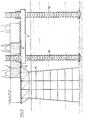
- Figure 1 schematically shows the transfer phase of a complete equipment 1, mounted and received on land, on a self-elevating platform 2.
- the self-elevating platform is moored to platform 3 so that the transfer means provided on the deck of the platform are approximately in line with those of the platform.
- These transfer means consist respectively of paths 4 and sliding rails 5.
- the cradle 6, which forms part of the transfer means and which supports the equipment, consisting of living quarters, technical premises and possibly the drilling tower, is mounted on transfer supports constituted, for example, of five rows of three pads 7 also spaced according to what will be called the length of the cradle.
- the spacing of the pads on a row corresponds to the spacing of the rails 5 and the sliding paths 4.
- the pads are mounted on flat cylinders so as to optionally allow the transfer of loads from one row of pads to the other rows of pads as will be described later.
- a template 8 is provided which is arranged between the platform 3 and the deck of the platform 2 This template carries guides 9 which connect the rails 5 to the paths 4.
- the transfer of the equipment takes place, in this example in a known manner, by sliding. But at this stage of the transport process any other means or method can be used and even possibly lifting by crane or gantry.
- the loading taking place in a generally calm coastal zone, does not present any particular difficulties.
- the self-elevating transport platform 2 is kept floating for receiving the load. It is not however excluded to make it rest on its feet 10.
- the load supported by the row of skids arriving on the template between platform 3 and platform 2 is transferred to the other rows of skates which rest either on the platform or on the jack-up platform .
- the self-lifting platform 2 When the self-lifting platform 2 is loaded, it is towed to the site and then stowed near the fixed platform 11.
- the platform 2 is positioned so as to bring its transfer means approximately into alignment with those provided on the platform 11, then the bridge of the self-elevating platform 2 is raised at the level of the bridge of the platform. fixed form 11.
- the two bridges are coupled by a guide frame 12 which has the function of maintaining the relative positions of the platforms relative to each other in the horizontal plane.
- the transfer of the load 1 is carried out from the self-lifting platform 2 to the fixed platform 11, in a known manner, by sliding.
- the sliding paths 4 provided both on the fixed platform and on the self-elevating platform are relatively wide compared to the pads 7 of the cradle 6 carrying the load. This allows a transverse offset of the module during transfer due, for example, to a positioning defect of the paths of the two bridges, an offset which is easily compensated for during sliding.
Landscapes
- Engineering & Computer Science (AREA)
- Mechanical Engineering (AREA)
- General Engineering & Computer Science (AREA)
- Civil Engineering (AREA)
- Structural Engineering (AREA)
- Chemical & Material Sciences (AREA)
- Combustion & Propulsion (AREA)
- Ocean & Marine Engineering (AREA)
- Architecture (AREA)
- Transportation (AREA)
- Bridges Or Land Bridges (AREA)
- Ship Loading And Unloading (AREA)
- Auxiliary Methods And Devices For Loading And Unloading (AREA)
- Tires In General (AREA)
- Types And Forms Of Lifts (AREA)
- Refuse Collection And Transfer (AREA)
- Vehicle Body Suspensions (AREA)
- Conveying And Assembling Of Building Elements In Situ (AREA)
Description
- L'invention concerne un procédé de transport et de transfert d'une charge constituée d'un équipement complet d'un pont de plate-forme marine fixe consistant à monter la totalité des installations d'un pont dans un chantier à terre, à transférer l'équipement complet sur des moyens de transport remorqués sur le site et à transférer ledit équipement sur le pont de la plate-forme à équiper.
- L'infrastructure des plates-formes est généralement construite à terre, en une ou plusieurs parties qui sont remorquées sur le site, assemblées, puis immergées par contrôle de leur flottabilité. Le pont est ensuite équipé des installations correspondant à la destination de la plate-forme. Ces installations sont réalisées à partir de modules de poids et de dimensions standards, qui sont assemblés les uns aux autres in situ. Dans les mers à conditions climatiques normales, le levage et la mise en place des modules sont réalisés par des grues barges et des engins semi-submersibles classiques. Par contre l'utilisation de ces mêmes engins dans des mers aux conditions climatiques difficiles ne permet pas une efficacité suffisante pendant les très courtes périodes où les conditions atmosphériques autorisent le travail dans des conditions de sécurité suffisantes. Afin de diminuer les temps nécessaires au levage et à la mise en place des éléments et par conséquent de diminuer les risques climatiques, ainsi que les coûts de manutention et autres dépenses directes, on a cherché à augmenter la capacité de levage des grues barges et des semi-submersibles mais l'on a atteint une limite au-delà de laquelle les engins sont si coûteux que leur rentabilité ne peut être obtenue que par un taux d'utilisation journalier important.
- Malheureusement l'amortissement de ces engins ne peut être envisagé que sur quelques projets.
- Il subsiste en outre des inconvénients sérieux dus aux procédés employés, ainsi les risques, inhérents à tout levage en mer, augmentent proportionnellement au poids levé, de même que ceux dus au transfert d'une charge d'un engin flottant à une installation fixe.
- Le temps nécessaire à l'installation des équipements, à leur essai et à leur réception n'en est pas pour cela diminué.
- L'installation fait appel à un grand nombre de personnes qui doivent s'accommoder de conditions d'habitat difficiles aggravées par les conditions climatiques.
- Une solution à ces problèmes a été trouvée dans EP-A-0 094 434 qui utilise pour le transport de la charge une plate-forme auto-élévatrice selon le préambule de la revendication 1. Le transfert de la charge est obtenu en mettant le pont de la plate-forme auto-élévatrice au niveau du quai de chargement ou du pont de la plate-forme fixe sur laquelle doit être transféré la charge. On amène la plate-forme auto-élévatrice le plus près possible de la plate-forme fixe de manière à aligner le mieux possible les chemins de glissement sur lesquels la charge sera poussée et l'on règle la hauteur des pieds de la plate-forme de manière à mettre les ponts au même niveau. On procède ensuite au transfert de la charge par glissement.
- Cette méthode présente l'inconvénient de nécessiter une approche précise de la plate-forme de manière à accoupler directement les deux ponts et de prévoir sur l'un des deux ponts une partie en porte-à-faux afin de diminuer les risques de frottement lors de l'approche et de l'accouplement des ponts.
- Selon l'invention définie par les caractéristiques de la revendication 1, le transport et le transfert des équipements sont réalisés à partir d'une plate-forme auto-élévatrice susceptible d'être reliée pour le chargement ou le déchargement au quai d'embarquement et à la plate-forme à équiper, à l'aide de moyens de transfert délestant. l'une ou l'autre des plates-formes de la charge lors de son transfert.
- Les explications et figures données ci-après à titre d'exemple permettront de comprendre comment l'invention peut être réalisée.
- La figure 1 représente la phase de transfert de l'équipement d'un quai à une plate-forme auto-élévatrice.
- La figure 2 est une vue de dessus de la figure 1 montrant une partie des moyens de transfert.
- La figure 3 représente la phase de transfert de l'équipement d'une plate-forme auto-élévatrice à la plate-forme à équiper.
- La figure 1 montre schématiquement la phase de transfert d'un équipement complet 1, monté et réceptionné à terre, sur une plate-forme 2 auto-élévatrice. De manière connue, la plate-forme auto-élévatrice est amarrée au quai 3 de manière que les moyens de transfert prévus sur le pont de la plate-forme soient approximativement dans le prolongement de ceux du quai. Ces moyens de transfert sont constitués respectivement de chemins 4 et de rails 5 de glissement. Le berceau 6, qui forme une partie des moyens de transfert et qui supporte l'équipement, constitué des locaux d'habitation, des locaux techniques et éventuellement de la tour de forage, est monté sur des supports de transfert constitués, par exemple, de cinq rangées de trois patins 7 également espacées selon ce que l'on conviendra d'appeler la longueur du berceau. L'espacement des patins sur une rangée correspond à l'espacement des rails 5 et des chemins 4 de glissement. Les patins sont montés sur des vérins plats de manière à permettre éventuellement un transfert des charges d'une rangée de patins aux autres rangées de patins comme il sera ultérieurement décrit.
- Afin d'assurer l'alignement au moins approximatif entre les rails 5 et les chemins 4 de glissement de la plate-forme, il est prévu un gabarit 8 que l'on dispose entre le quai 3 et le pont de la plate-forme 2. Ce gabarit porte des guides 9 qui relient les rails 5 aux chemins 4.
- Le transfert de l'équipement s'opère, dans cet exemple de manière connue, par glissement. Mais à ce stade du procédé de transport tous autres moyens ou méthodes peuvent être utilisés et même éventuellement le levage par grue ou portique. Le chargement, s'opérant en zone côtière généralement calme, ne présente pas de difficultés particulières.
- La plate-forme auto-élévatrice 2 de transport est maintenue en flottaison pour la réception de la charge. Il n'est toutefois pas exclu de la faire reposer sur ses pieds 10.
- Dans le transfert par glissement, on évite que le gabarit 8 disposé entre le quai et la plate-forme ne supporte de charge.
- Pour ce faire, la charge supportée par la rangée de patins arrivant sur le gabarit entre le quai 3 et la plate-forme 2, est transférée aux autres rangées de patins qui reposent soit sur le quai, soit sur la plate-forme auto-élévatrice.
- Lorsque la plate-forme auto-élévatrice 2 est chargée, elle est remorquée sur le site puis arrimée près de la plate-forme fixe 11.
- On positionne la plate-forme 2 de manière à mettre approximativement ses moyens de transfert en alignement avec ceux prévus sur la plate-forme 11, puis on lève le pont de la plate-forme auto-élévatrice 2 au niveau du pont de la plate-forme fixe 11. On accouple les deux ponts par un châssis de guidage 12 qui a pour fonction de maintenir les positions relatives des plates-formes l'une par rapport à l'autre dans le plan horizontal.
- On opère le transfert de la charge 1, de la plate-forme auto-élévatrice 2 à la plate-forme fixe 11, de manière connue, par glissement.
- La rangée de patins s'engageant sur le châssis 12 entre les deux plates-formes est délestée de la charge au profit des autres rangées de patins reposant sur l'un ou les deux ponts.
- Lorsque le transfert de la charge est terminé, les deux ponts sont désaccouplés par retrait du châssis de guidage 12.
- On met la plate-forme auto-élévatrice en flottaison en remontant ses pieds et on en dispose en vue d'autres utilisations et notamment celle-ci peut être équipée d'une grue et de quartier d'habitation de façon à exécuter éventuellement la fin des travaux.
- Il est à remarquer que les chemins de glissement 4 prévus aussi bien sur la plate-forme fixe que sur la plate-forme auto-élévatrice sont relativement larges par rapport aux patins 7 du berceau 6 portant la charge. Ceci permet un décalage transversal du module lors du transfert dû, par exemple, à un défaut de positionnement des chemins des deux ponts, décalage qui est facilement rattrapable lors du glissement.
- La modification de destination de la plate-forme fixe est aisément réalisable en transférant, selon le même procédé l'équipement du pont de la plate-forme fixe au pont de la plate-forme auto-élévatrice et en le remplaçant lors d'un transfert ultérieur par un équipement adapté à la nouvelle utilisation de la plate-forme fixe.
Claims (5)
Priority Applications (1)
| Application Number | Priority Date | Filing Date | Title |
|---|---|---|---|
| AT86400882T ATE41388T1 (de) | 1985-04-24 | 1986-04-23 | Verfahren zum transport und zur uebergabe einer schweren last auf see auf eine feststehende konstruktion. |
Applications Claiming Priority (2)
| Application Number | Priority Date | Filing Date | Title |
|---|---|---|---|
| FR8506232A FR2581020A1 (fr) | 1985-04-24 | 1985-04-24 | Procede de transport et de transfert d'une charge constituee d'un equipement complet d'un pont de plate-forme marine et moyens pour la mise en oeuvre du procede |
| FR8506232 | 1985-04-24 |
Publications (2)
| Publication Number | Publication Date |
|---|---|
| EP0204591A1 EP0204591A1 (fr) | 1986-12-10 |
| EP0204591B1 true EP0204591B1 (fr) | 1989-03-15 |
Family
ID=9318625
Family Applications (1)
| Application Number | Title | Priority Date | Filing Date |
|---|---|---|---|
| EP86400882A Expired EP0204591B1 (fr) | 1985-04-24 | 1986-04-23 | Procédé de transport et de transfert en mer d'une charge lourde à une structure fixe |
Country Status (7)
| Country | Link |
|---|---|
| US (1) | US4826355A (fr) |
| EP (1) | EP0204591B1 (fr) |
| AT (1) | ATE41388T1 (fr) |
| DE (1) | DE3662370D1 (fr) |
| FR (1) | FR2581020A1 (fr) |
| NO (1) | NO162656C (fr) |
| WO (1) | WO1986006340A1 (fr) |
Cited By (1)
| Publication number | Priority date | Publication date | Assignee | Title |
|---|---|---|---|---|
| CN102849185A (zh) * | 2012-09-18 | 2013-01-02 | 渤海装备辽河重工有限公司 | 一种自升式钻井平台的桩腿安装方法 |
Families Citing this family (20)
| Publication number | Priority date | Publication date | Assignee | Title |
|---|---|---|---|---|
| NO165910C (no) * | 1988-06-16 | 1991-05-02 | Per Tybring Aralt | Fremgangsmaate og anordning for transport av tunge kolli. |
| US5097786A (en) * | 1988-09-27 | 1992-03-24 | Sheffield Woodrow W | Method and apparatus for erecting and removing offshore structures |
| US5139367A (en) * | 1989-10-31 | 1992-08-18 | Transworld Drilling Co. | System for moving drilling module to fixed platform |
| US4938628A (en) * | 1989-10-31 | 1990-07-03 | Transworld Drilling Company | System for moving drilling module to fixed platform |
| US4973198A (en) * | 1989-12-28 | 1990-11-27 | Shell Oil Company | Offshore drilling rig transfer |
| MX9101961A (es) * | 1990-11-06 | 1992-07-08 | Rowan Co Inc | Metodo y aparato para transferir un aparato de perforacion desde un deposito movible hasta una estructura fija |
| US5290128A (en) * | 1990-11-06 | 1994-03-01 | Rowan Companies, Inc. | Method and apparatus for transferring a drilling apparatus from a movable vessel to a fixed structure |
| CA2133836C (fr) * | 1992-04-06 | 2004-01-20 | Daniel Frank Mcnease | Methode et dispositif pour deplacer une grue ou une plate-forme de forage a partir d'un batiment flottant |
| US5419657A (en) * | 1992-05-08 | 1995-05-30 | Rowan Companies, Inc. | Method and apparatus for transferring a structure from a jack-up rig to a fixed platform |
| US5558468A (en) * | 1994-07-15 | 1996-09-24 | Andrew C. Barnett, Jr. | Method and apparatus for erecting a marine structure |
| NL1016859C2 (nl) * | 2000-12-13 | 2002-06-14 | Marine Construct B V | Werkwijze en inrichting voor het plaatsen van ten minste ÚÚn windmolen op open water. |
| US6718901B1 (en) * | 2002-11-12 | 2004-04-13 | Technip France | Offshore deployment of extendable draft platforms |
| BRPI0718975A2 (pt) * | 2006-11-22 | 2014-02-04 | Technip France | Estrutura de transporte, de instalação e de desmantelamento de uma ponte de uma plataforma petrolífera de exploração no mar e processos de transporte e de instalação de uma ponte de uma plataforma petrolífera até um sítio de exploração e de desmantelamento e de transporte de uma ponte de uma plataforma petrolífera de um sítio de exploração até um elemento de transporte por flutuação |
| FR2923454B1 (fr) * | 2007-11-09 | 2010-01-15 | Freyssinet | Procede de transport en milieu aquatique d'un ouvrage civil |
| IT1400399B1 (it) * | 2009-07-17 | 2013-05-31 | In Novo D O O | Pontone autosollevante |
| DE202012004349U1 (de) * | 2012-05-04 | 2013-08-05 | Olb Offshore Logistics Bremerhaven Gmbh | Ponton für den Transport großer und schwerer Lasten |
| US11142411B2 (en) * | 2015-03-04 | 2021-10-12 | Shibakai Co., Ltd. | Cargo handling method |
| CN107687163B (zh) * | 2016-08-05 | 2019-11-01 | 中集海洋工程研究院有限公司 | 自升式平台悬臂梁的耐磨板更换方法 |
| CN112319731A (zh) * | 2020-11-20 | 2021-02-05 | 天津博迈科海洋工程有限公司 | 一种大型海工设备安装方法 |
| CN113338223B (zh) * | 2021-06-09 | 2022-09-20 | 上海振华重工(集团)股份有限公司 | 一种调整卸载载荷的方法 |
Family Cites Families (10)
| Publication number | Priority date | Publication date | Assignee | Title |
|---|---|---|---|---|
| US2997852A (en) * | 1954-12-30 | 1961-08-29 | De Long Corp | Apparatus and method for reecting a supporting structure over a body of water |
| FR1214760A (fr) * | 1958-02-03 | 1960-04-12 | Bataafsche Petroleum | Procédé pour enlever une plate-forme d'un dispositif à supports placé dans l'eauou pour l'y poser et installation pour exécuter ce procédé |
| NL135005C (fr) * | 1967-10-11 | 1972-09-15 | ||
| US4055264A (en) * | 1975-08-04 | 1977-10-25 | Brown & Root, Inc. | Deck section loading |
| FR2405182A1 (fr) * | 1977-10-04 | 1979-05-04 | Metalliques Entrepr Cie Fse | Procede et equipement pour la mise en place sur colonnes ancrees au fond, a partir d'un navire transporteur, de chargements, plates-formes ou analogues, pour installations au large des cotes |
| NL7805807A (nl) * | 1978-05-29 | 1979-12-03 | Heusden Verolme Scheeps | Dokschip. |
| FR2514317A1 (fr) * | 1981-10-12 | 1983-04-15 | Doris Dev Richesse Sous Marine | Dispositif de levage et de transport de charge, a flottabilite reglable, pour travaux en mer et procede pour la mise en oeuvre dudit dispositif |
| JPS5878296U (ja) * | 1981-11-24 | 1983-05-26 | 日立造船株式会社 | 大型海洋構造物据付用作業船 |
| JPS5880430U (ja) * | 1981-11-25 | 1983-05-31 | 日立造船株式会社 | 大型海洋構造物据付用作業船 |
| JPS6054454B2 (ja) * | 1982-11-17 | 1985-11-30 | 日立造船株式会社 | 大型海洋構造物の移送方法 |
-
1985
- 1985-04-24 FR FR8506232A patent/FR2581020A1/fr not_active Withdrawn
-
1986
- 1986-04-23 AT AT86400882T patent/ATE41388T1/de active
- 1986-04-23 EP EP86400882A patent/EP0204591B1/fr not_active Expired
- 1986-04-23 DE DE8686400882T patent/DE3662370D1/de not_active Expired
- 1986-04-23 WO PCT/FR1986/000138 patent/WO1986006340A1/fr not_active Ceased
- 1986-12-19 NO NO865171A patent/NO162656C/no unknown
-
1988
- 1988-08-30 US US07/239,007 patent/US4826355A/en not_active Expired - Fee Related
Cited By (2)
| Publication number | Priority date | Publication date | Assignee | Title |
|---|---|---|---|---|
| CN102849185A (zh) * | 2012-09-18 | 2013-01-02 | 渤海装备辽河重工有限公司 | 一种自升式钻井平台的桩腿安装方法 |
| CN102849185B (zh) * | 2012-09-18 | 2015-01-21 | 中国石油集团渤海石油装备制造有限公司 | 一种自升式钻井平台的桩腿安装方法 |
Also Published As
| Publication number | Publication date |
|---|---|
| ATE41388T1 (de) | 1989-04-15 |
| FR2581020A1 (fr) | 1986-10-31 |
| NO162656B (no) | 1989-10-23 |
| EP0204591A1 (fr) | 1986-12-10 |
| NO865171L (no) | 1986-12-19 |
| DE3662370D1 (en) | 1989-04-20 |
| US4826355A (en) | 1989-05-02 |
| WO1986006340A1 (fr) | 1986-11-06 |
| NO162656C (no) | 1990-01-31 |
Similar Documents
| Publication | Publication Date | Title |
|---|---|---|
| EP0204591B1 (fr) | Procédé de transport et de transfert en mer d'une charge lourde à une structure fixe | |
| EP0090006B1 (fr) | Dispositif flottant et procede de levage et de transport de charge | |
| CN101903235A (zh) | 安装离岸风轮机的方法与驳船系统 | |
| EP2199199B1 (fr) | Système de support de turbine hydroélectrique | |
| EP2389311B1 (fr) | Préchargement pour réduire les charges et préserver l'acier sur les uvres mortes et le filet de systèmes de catamaran | |
| EP2454149A1 (fr) | Bateau de type catamaran utile pour l'assemblage, le transport et la dépose au fond de la mer d'éolienne maritime | |
| EP2812239B1 (fr) | Plateforme semi-submersible dotée d'une plateforme submersible mobile pour mise en cale sèche d'un navire | |
| FR3067047B1 (fr) | Procede de mise a l'eau | |
| US20030226490A1 (en) | Work module support vessel | |
| CN115893042A (zh) | 一种风电管桩滑移上船的方法 | |
| WO2003066426A1 (fr) | Ponton-grue ballastable et procede de levage, de transport, de positionnement et d'installation d'une structure marine, notamment d'au moins un aerogenerateur | |
| EP3674199A1 (fr) | Déclassement de structures offshore | |
| WO2001090487A1 (fr) | Procede de transport et d'installation d'un pont de plate-forme | |
| FR2940244A1 (fr) | Passerelle pour le chargement et le dechargement d'un navire roulier | |
| EP4259927B1 (fr) | Procédé d'assemblage d'un parc éolien offshore flottant | |
| GB2315464A (en) | Transporting offshore structures | |
| FR2970748A1 (fr) | Procede pour la realisation d'operations de maintenance sur un dispositif d'eolienne flottante offshore et systeme correspondant | |
| CN111279032B (zh) | 港口设备和用于将浮体系泊在港口设备中的方法 | |
| FR3140065A1 (fr) | Plateforme flottante off-shore pour fabrication, assemblage, maintenance et/ou démontage d’éoliennes flottantes | |
| GB2303337A (en) | Offshore operations vessel | |
| RU2309221C2 (ru) | Комплекс для монтажа морской ледостойкой переставной платформы и способ ее транспортировки и монтажа посредством комплекса для монтажа | |
| US12539947B2 (en) | Installation system and method for an offshore wind turbine | |
| EP0097069B1 (fr) | Procédé d'installation d'une plateforme en mer, superstructure de plateforme pour la mise en oeuvre de ce procédé | |
| US20240270356A1 (en) | Installation System and Method For An Offshore Wind Turbine | |
| FR2943079A1 (fr) | Systeme et procede d'immersion d'une turbomachine hydraulique |
Legal Events
| Date | Code | Title | Description |
|---|---|---|---|
| PUAI | Public reference made under article 153(3) epc to a published international application that has entered the european phase |
Free format text: ORIGINAL CODE: 0009012 |
|
| AK | Designated contracting states |
Kind code of ref document: A1 Designated state(s): AT BE CH DE FR GB IT LI LU NL SE |
|
| 17P | Request for examination filed |
Effective date: 19870218 |
|
| 17Q | First examination report despatched |
Effective date: 19871105 |
|
| GRAA | (expected) grant |
Free format text: ORIGINAL CODE: 0009210 |
|
| AK | Designated contracting states |
Kind code of ref document: B1 Designated state(s): AT BE CH DE FR GB IT LI LU NL SE |
|
| REF | Corresponds to: |
Ref document number: 41388 Country of ref document: AT Date of ref document: 19890415 Kind code of ref document: T |
|
| GBT | Gb: translation of ep patent filed (gb section 77(6)(a)/1977) | ||
| REF | Corresponds to: |
Ref document number: 3662370 Country of ref document: DE Date of ref document: 19890420 |
|
| PGFP | Annual fee paid to national office [announced via postgrant information from national office to epo] |
Ref country code: CH Payment date: 19890421 Year of fee payment: 4 |
|
| PGFP | Annual fee paid to national office [announced via postgrant information from national office to epo] |
Ref country code: FR Payment date: 19890426 Year of fee payment: 4 Ref country code: AT Payment date: 19890426 Year of fee payment: 4 |
|
| PGFP | Annual fee paid to national office [announced via postgrant information from national office to epo] |
Ref country code: SE Payment date: 19890428 Year of fee payment: 4 |
|
| PG25 | Lapsed in a contracting state [announced via postgrant information from national office to epo] |
Ref country code: LU Free format text: LAPSE BECAUSE OF NON-PAYMENT OF DUE FEES Effective date: 19890430 |
|
| PGFP | Annual fee paid to national office [announced via postgrant information from national office to epo] |
Ref country code: NL Payment date: 19890430 Year of fee payment: 4 |
|
| PGFP | Annual fee paid to national office [announced via postgrant information from national office to epo] |
Ref country code: DE Payment date: 19890519 Year of fee payment: 4 |
|
| PGFP | Annual fee paid to national office [announced via postgrant information from national office to epo] |
Ref country code: LU Payment date: 19890522 Year of fee payment: 4 |
|
| ITF | It: translation for a ep patent filed | ||
| PGFP | Annual fee paid to national office [announced via postgrant information from national office to epo] |
Ref country code: BE Payment date: 19890613 Year of fee payment: 4 |
|
| PLBE | No opposition filed within time limit |
Free format text: ORIGINAL CODE: 0009261 |
|
| STAA | Information on the status of an ep patent application or granted ep patent |
Free format text: STATUS: NO OPPOSITION FILED WITHIN TIME LIMIT |
|
| 26N | No opposition filed | ||
| PG25 | Lapsed in a contracting state [announced via postgrant information from national office to epo] |
Ref country code: GB Effective date: 19900423 Ref country code: AT Effective date: 19900423 |
|
| PG25 | Lapsed in a contracting state [announced via postgrant information from national office to epo] |
Ref country code: SE Effective date: 19900424 |
|
| ITTA | It: last paid annual fee | ||
| PG25 | Lapsed in a contracting state [announced via postgrant information from national office to epo] |
Ref country code: LI Effective date: 19900430 Ref country code: CH Effective date: 19900430 Ref country code: BE Effective date: 19900430 |
|
| BERE | Be: lapsed |
Owner name: MODULAR JACK-UP SYSTEMS CY INC. Effective date: 19900430 |
|
| PG25 | Lapsed in a contracting state [announced via postgrant information from national office to epo] |
Ref country code: NL Effective date: 19901101 |
|
| NLV4 | Nl: lapsed or anulled due to non-payment of the annual fee | ||
| GBPC | Gb: european patent ceased through non-payment of renewal fee | ||
| PG25 | Lapsed in a contracting state [announced via postgrant information from national office to epo] |
Ref country code: FR Effective date: 19901228 |
|
| REG | Reference to a national code |
Ref country code: CH Ref legal event code: PL |
|
| PG25 | Lapsed in a contracting state [announced via postgrant information from national office to epo] |
Ref country code: DE Effective date: 19910101 |
|
| REG | Reference to a national code |
Ref country code: FR Ref legal event code: ST |
|
| EUG | Se: european patent has lapsed |
Ref document number: 86400882.6 Effective date: 19910116 |
|
| PG25 | Lapsed in a contracting state [announced via postgrant information from national office to epo] |
Ref country code: IT Free format text: LAPSE BECAUSE OF NON-PAYMENT OF DUE FEES;WARNING: LAPSES OF ITALIAN PATENTS WITH EFFECTIVE DATE BEFORE 2007 MAY HAVE OCCURRED AT ANY TIME BEFORE 2007. THE CORRECT EFFECTIVE DATE MAY BE DIFFERENT FROM THE ONE RECORDED. Effective date: 20050423 |