EP0203477B1 - Refrigerant gas injection system for refrigeration cycle having a screw compressor - Google Patents
Refrigerant gas injection system for refrigeration cycle having a screw compressor Download PDFInfo
- Publication number
- EP0203477B1 EP0203477B1 EP86106673A EP86106673A EP0203477B1 EP 0203477 B1 EP0203477 B1 EP 0203477B1 EP 86106673 A EP86106673 A EP 86106673A EP 86106673 A EP86106673 A EP 86106673A EP 0203477 B1 EP0203477 B1 EP 0203477B1
- Authority
- EP
- European Patent Office
- Prior art keywords
- screw compressor
- refrigerant
- gas injection
- oil
- pressure
- Prior art date
- Legal status (The legal status is an assumption and is not a legal conclusion. Google has not performed a legal analysis and makes no representation as to the accuracy of the status listed.)
- Expired
Links
Images

Classifications
-
- F—MECHANICAL ENGINEERING; LIGHTING; HEATING; WEAPONS; BLASTING
- F04—POSITIVE - DISPLACEMENT MACHINES FOR LIQUIDS; PUMPS FOR LIQUIDS OR ELASTIC FLUIDS
- F04C—ROTARY-PISTON, OR OSCILLATING-PISTON, POSITIVE-DISPLACEMENT MACHINES FOR LIQUIDS; ROTARY-PISTON, OR OSCILLATING-PISTON, POSITIVE-DISPLACEMENT PUMPS
- F04C28/00—Control of, monitoring of, or safety arrangements for, pumps or pumping installations specially adapted for elastic fluids
- F04C28/10—Control of, monitoring of, or safety arrangements for, pumps or pumping installations specially adapted for elastic fluids characterised by changing the positions of the inlet or outlet openings with respect to the working chamber
- F04C28/12—Control of, monitoring of, or safety arrangements for, pumps or pumping installations specially adapted for elastic fluids characterised by changing the positions of the inlet or outlet openings with respect to the working chamber using sliding valves
- F04C28/125—Control of, monitoring of, or safety arrangements for, pumps or pumping installations specially adapted for elastic fluids characterised by changing the positions of the inlet or outlet openings with respect to the working chamber using sliding valves with sliding valves controlled by the use of fluid other than the working fluid
-
- F—MECHANICAL ENGINEERING; LIGHTING; HEATING; WEAPONS; BLASTING
- F25—REFRIGERATION OR COOLING; COMBINED HEATING AND REFRIGERATION SYSTEMS; HEAT PUMP SYSTEMS; MANUFACTURE OR STORAGE OF ICE; LIQUEFACTION SOLIDIFICATION OF GASES
- F25B—REFRIGERATION MACHINES, PLANTS OR SYSTEMS; COMBINED HEATING AND REFRIGERATION SYSTEMS; HEAT PUMP SYSTEMS
- F25B1/00—Compression machines, plants or systems with non-reversible cycle
- F25B1/04—Compression machines, plants or systems with non-reversible cycle with compressor of rotary type
- F25B1/047—Compression machines, plants or systems with non-reversible cycle with compressor of rotary type of screw type
-
- F—MECHANICAL ENGINEERING; LIGHTING; HEATING; WEAPONS; BLASTING
- F25—REFRIGERATION OR COOLING; COMBINED HEATING AND REFRIGERATION SYSTEMS; HEAT PUMP SYSTEMS; MANUFACTURE OR STORAGE OF ICE; LIQUEFACTION SOLIDIFICATION OF GASES
- F25B—REFRIGERATION MACHINES, PLANTS OR SYSTEMS; COMBINED HEATING AND REFRIGERATION SYSTEMS; HEAT PUMP SYSTEMS
- F25B41/00—Fluid-circulation arrangements
- F25B41/20—Disposition of valves, e.g. of on-off valves or flow control valves
-
- F—MECHANICAL ENGINEERING; LIGHTING; HEATING; WEAPONS; BLASTING
- F25—REFRIGERATION OR COOLING; COMBINED HEATING AND REFRIGERATION SYSTEMS; HEAT PUMP SYSTEMS; MANUFACTURE OR STORAGE OF ICE; LIQUEFACTION SOLIDIFICATION OF GASES
- F25B—REFRIGERATION MACHINES, PLANTS OR SYSTEMS; COMBINED HEATING AND REFRIGERATION SYSTEMS; HEAT PUMP SYSTEMS
- F25B2400/00—Component parts or details not otherwise provided for in this subclass
- F25B2400/13—Economisers
Definitions
- the present invention relates to a refrigerant gas injection system for a refrigeration cycle, said system having a screw compressor provided with a slide valve for controlling the compression capacity of said screw compressor, a condenser and an economizer disposed in a passage connected to a refrigerant liquid outlet of the condenser and adapted for subcooling said refrigerant liquid by the refrigerant of a reduced pressure, and a refrigerant gas injection line through which the refrigerant gas generated in said economizer is injected into the compression chamber of said screw compressor in its compression phase.
- a known refrigeration system employing the abovementioned economizer cylce incorporates a screw compressor having a capacity controlling or unloading means constituted by a slide valve.
- the refrigerant gas which has subcooled the refrigerant liquid in the subcooling device is injected into the compression chamber of a screw compressor in the compression phase so as to avoid any reduction in the refrigeration power.
- Such a gas injection system for injecting refrigerant gas into a screw compressor is disclosed, for example, in the specification of United States Patent No. 4,005,949.
- This known gas injection system suffers from a disadvantage in that the injected refrigerant gas is undesirably introduced into the suction side of the screw compressor, if the gas injection is performed when the screw compressor is operating in the unloaded state with its slide valve opened. This detracts the merit of the refrigerant gas injection and causes various unfavourable effects.
- the object of the invention is to provide a refrigerant gas injection system which is improved in such a manner that the injection of the refrigerant gas is stopped automatically when the screw compressor is unloaded, thereby obviating the abovedescribed problems of the prior art while enabling full use of the merit of the economizer cycle.
- the refrigerant gas injection system of the generic kind comprises an oil supplying valve disposed in an oil passage communicated with an oil supplying passage and operated in response to the detection signal of a refrigerant pressure at the suction side of said screw compressor or the temperature of the cooling water at the outlet of an evaporator in such a manner that pressurized oil is supplied to actuators for actuating said slide valve to bring said screw compressor from a full load level to the unloaded state and vice versa; and a gas injection solenoid valve disposed in said gas injection line and operated in response to the detection signal of the pressure at said actuator, so that said solenoid valve operates in relation to the operation of said oil supplying means in such a manner as to open when said screw compressor is operating at full load level and to close when the same is operating in the unloaded state.
- a refrigeration cycle incorporates a screw compressor having a casing 1 which rotatably accommodates a pair of screw rotors 2 one of which is drivingly connected to a driving motor (not shown).
- a discharge pipe 3 is connected to the casing 1 so as to communicate with a discharge chamber 31 through a discharge port 15.
- An oil separator 4 is connected to the discharge pipe 3. The upper space 41 in the oil separator 4 is communicated with the condenser 7 through a discharge gas pipe 6.
- a reference numeral 6a denotes a refrigerant liquid pipe which is connected at its one end to the refrigerant outlet of the condenser 7, while the other end is connected to a subcooling device (referred to as an « economizer » hereinunder) which is denoted by a numeral 8.
- a main expansion valve 9 as a pressure reducing means is connected to the outlet side of the economizer 8.
- a reference numeral 10 designates an auxiliary expansion valve which is connected to a branch pipe branching from the refrigerant liquid pipe 6a. The outlet of the auxiliary expansion valve 10 is connected to the economizer 8 so that the refrigerant expanded through the auxiliary expansion valve 10 subcools the refrigerant liquid which flows through the economizer 8.
- An evaporator 12 is connected at its inlet side to the main expansion valve 9 and at its outlet side to a suction chamber 32 of the screw compressor through the suction pipe 13 past the suction port 14.
- a reference numeral 11 designates a gas introduction pipe which is connected at its one end to the outlet side of the economizer 8.
- the other end of the gas introduction pipe 11 leads to a gas injection port 20 formed in the casing 1 through a gas injection solenoid valve 26.
- the gas injection port 20 is so positioned that it can communicates with the compression chamber which is in its compression process.
- a slide valve 16, which constitutes an unloading means, is integrated with a piston 17a through a piston rod 17.
- the piston 17a is slidably received in a cylinder 18.
- the piston 17a is urged by a spring 27 so that the slide valve 16 is kept opened while a pressure balance is maintained in the screw compressor during operation thereof.
- the piston rod 17, piston 17a, spring 27 and the cylinder 18 in combination constitute an actuator for actuating the slide valve 16.
- the arrangement is such that, when the slide valve 16. is opened to unload the screw compressor, a part of the compressed refrigerant gas is relieved into a space 28 which leads to the low-pressure side of the compressor, whereby the amount of the gas finally compressed is decreased.
- the space in the cylinder 18 is divided by the piston 17a into two sections : namely, a cylinder chamber 18 which is on the left side of the piston 17a as viewed in Fig. 1 and a back chamber 18b which is on the right side of the piston 17a.
- a reference numeral 19 denotes a capacity detecting hole which is formed in the wall of the cylinder 18 at a position where the piston 17a is located when the screw compressor is operating at 100 % capacity or load.
- a pressure switch 25 is connected to the capacity detection hole 19 through a pressure detection pipe 29, so as to be opened and closed in response to a change in the pressure within the back chamber 18b within the cylinder.
- the pressure switch 25 is electrically connected to the gas injection solenoid valve 26 in series thereto. The arrangement is such, when the contactor 25a of the pressure switch 25 makes contact, the solenoid coil 26c of the gas injection solenoid valve 26 is energized to open the solenoid valve 26.
- An oil supply port 24 is formed in the wall of the cylinder 18 in such a manner as to open to the cylinder 18a.
- An oil supply passage 5 leading from the oil well in the oil separator 4 and having an oil supply solenoid valve 21 is connected to the oil supply port 24.
- a branch oil passage 51 branches from a portion of the oil supply passage 5 between the oil supply port 24 and the oil supply solenoid valve 21.
- the branch oil pipe is communicated with a port 23 formed in the suction side of the casing 1 through a low-pressure equalizer valve 22.
- a reference numeral 30 denotes a port which is communicated with a chamber 33 which in turn is connected to the back chamber 18b.
- the port 30 is connected through an equalizer passage 34 to the oil branch passage 51 leading to the port 23 and, therefore, is always held in communication with the low-pressure side.
- a reference numeral 35 designates a stopper portion which stops the piston 17a when the piston 17a has been fully moved to the right as viewed in Fig. 1, thus limiting the rightward stroking of the piston 17a.
- the operation of the refrigeration cycle is as follows.
- the refrigerant gas sucked into the screw compressor is compressed to a high pressure and temperature, and is introduced through the discharge pipe 3 into the oil separator 4 where the oil suspended by the refrigerant gas is separated from the oil.
- the separated oil is supplied through the oil supply pipe 5 to the portions of the screw compressor which need the lubrication.
- the refrigerant gas which is now free of the oil is introduced into the condenser 7 through the discharge pipe 6.
- the refrigerant is then condensed into a liquid phase as a result of heat exchange with cooling water which is supplied to and discharged from the. condenser 7 as indicated by broken-line arrows.
- the refrigerant liquid thus obtained is then introduced to the main expansion valve 9 through the economizer 8.
- the refrigerant gas expanded through the auxiliary expansion valve 10 is made to flow through the economizer 8 so as to subcool the refrigerant liquid flowing therethrough and is returned to the compression chamber of the screw compressor in a compression process through the gas introduction pipe 11.
- the refrigerant which has been expanded to lower pressure through the main expansion valve 9 is evaporated in the evaporator 12 through heat exchange with water which flows into and out of the evaporator 12 as indicated by broken-line arrows.
- the gaseous refrigerant of low pressure and temperature thus formed is then returned to the screw compressor 13 through the suction pipe 13.
- the refrigerant is thus recirculated through the refrigeration cycle while changing its phase between the liquid and gaseous phases.
- the advantage of the economizer cycle having the described construction resides in that the enthalpy possessed by the refrigerant and, hence, the refrigeration power of the refrigeration cycle is increased as the extent of subcooling effected in the economizer 8 is increased, and also in that the refrigerant gas expanded through the auxiliary expansion valve 10 and subcooled the refrigerant liquid is returned to the compression changer of the screw compressor in the compression phase so as to avoid reduction in the refrigeration power.
- the control of the capacity of the screw compressor is conducted in the following manner.
- the level of the refrigeration load is detected through sensing the refrigerant pressure at the suction side of the compressor or the temperature of the cooling water at the outlet of the evaporator.
- the oil supply solenoid valve 21 is opened, while the low-pressure equalizer solenoid valve 22 is closed, respectively, so that a pressurized oil is supplied into the cylinder chamber 18a on the left side of the piston 17a.
- the piston 17a is slided to the right as viewed in Fig. 1 so as to unload the compressor thereby reducing the capacity of the screw compressor.
- the solenoid valves 21 and 22 are closed and opened, respectively, the oil is relieved from the cylinder chamber 18a so that the piston 17a is slided to the left as viewed in Fig. 1 thereby, increasing the capacity.
- the amount of movement of the piston 17a is controlled by the opening periods of the solenoid valves 21 and 22.
- the cylinder chamber 18a on the left side of the piston 17a is a high-pressure chamber, while the back chamber 18b on the right side of the same is a low-pressure chamber. Therefore, the capacity detection hole 19 is formed at such a position that the pressure therein is changed from the high pressure to the low pressure when the piston 17a is moved to the position corresponding to 100 % load or capacity, as shown in Fig. 1.
- This pressure change is detected and changed into an electric signal by the pressure switch 25.
- the gas injection solenoid valve 26 provided in the gas introduction pipe 11 is controlled in accordance with this electric signal. Namely, when the screw compressor is operating at 100 % capacity or load level, it turns the gas injection solenoid valve 26 on thereby activating the economizer cycle, whereby the refrigerant gas from the economizer 8 is introduced to the gas injection port 20 and injected into the compression chamber of the screw compressor. However, when the screw compressor is operating at the other load level, i. e., in the unloaded state, the gas injection solenoid valve 26 is turned off to stop the injection of the refrigerant gas.
- the injection of the gas to the suction side is automatically stopped when the screw compressor is unloaded, so that the advantage of the economizer can be fully utilized without the risk of introduction of the refrigerant to the low pressure side.
- the 100 % capacity or load level is detected by sensing a change in the pressure. This detection system enables the invention to be applied easily to a refrigeration system employing a compressor such as a hermetic screw compressor with which it is generally difficult to find a change in the capacity or load level.
- Fig. 3 shows a modification in which the gas injection solenoid valve 26' for introducing the refrigerant gas is disposed in a pipe 61 a which is upstream of the auxiliary expansion valve 10. It will be clear that this modification produces the same advantage as that produced in the embodiment shown in Fig. 1.
- the capacity control by the slide valve can be broadly sorted into two types: namely, stepped type control and linear type control.
- the embodiment described hereinbefore employs the linear type control with which it is generally difficult to detect the 100 % capacity operation of the compressor.
- This embodiment employs an oil supply passage 100 which is connected at its one end to the oil reservoir of the oil separator 4, while the other end is connected to the oil supply port 24 of the casing 1.
- An oil supply solenoid valve 127 provided in an oil passage 102 is controlled in such a manner as to open when the compressor is operating at 100 % capacity or load level, while an unloading solenoid valve 128 provided in an unloading oil passage 101 is controlled in such a manner as to open when the load capacity is about 50 %.
- a reference numeral 190 designates a port which is formed at a position corresponding to the 50 % capacity operation.
- the unload solenoid valve 128 is closed and the gas injection solenoid valve 26 in the gas introduction pipe 11 is opened.
- the oil supply valve 127 is closed to cause a movement of the piston 17a so as to open the slide valve 16, while opening the unload solenoid valve 128, thereby relieving a part of the oil to the low-pressure side.
- the piston 17a is stably held at the position near the hole 190, so that the compressor stably operates in the unloaded state.
- the gas injection solenoid valve 126 is controlled in relation to the control of the solenoid valves 127, 128 so as to be closed during the unloaded operation of the screw compressor.
- the capacity of the screw compressor is controlled in a stepped manner such that the compressor operates either at the full (100 %) capacity or in unloaded state, i. e., at 50 % capacity, and the economizer cycle operates only when the screw compressor is operating at the full (100 %) capacity.
- the detection means for detecting the change in the pressure in the actuator for actuating the slide valve is constituted by the capacity detection hole 19 formed in the wall of the cylinder 18 and the pressure switch 25.
- This, however, is not exclusive and the change in the pressure can be detected by the other suitable means such as an external mechanical contact means which operates externally of the compressor in response to the movement of the piston 17a.
Landscapes
- Engineering & Computer Science (AREA)
- Mechanical Engineering (AREA)
- General Engineering & Computer Science (AREA)
- Physics & Mathematics (AREA)
- Thermal Sciences (AREA)
- Applications Or Details Of Rotary Compressors (AREA)
Description
- The present invention relates to a refrigerant gas injection system for a refrigeration cycle, said system having a screw compressor provided with a slide valve for controlling the compression capacity of said screw compressor, a condenser and an economizer disposed in a passage connected to a refrigerant liquid outlet of the condenser and adapted for subcooling said refrigerant liquid by the refrigerant of a reduced pressure, and a refrigerant gas injection line through which the refrigerant gas generated in said economizer is injected into the compression chamber of said screw compressor in its compression phase.
- A known refrigeration system employing the abovementioned economizer cylce incorporates a screw compressor having a capacity controlling or unloading means constituted by a slide valve. In such a refrigeration system, the refrigerant gas which has subcooled the refrigerant liquid in the subcooling device is injected into the compression chamber of a screw compressor in the compression phase so as to avoid any reduction in the refrigeration power.
- Such a gas injection system for injecting refrigerant gas into a screw compressor is disclosed, for example, in the specification of United States Patent No. 4,005,949. This known gas injection system, however, suffers from a disadvantage in that the injected refrigerant gas is undesirably introduced into the suction side of the screw compressor, if the gas injection is performed when the screw compressor is operating in the unloaded state with its slide valve opened. This detracts the merit of the refrigerant gas injection and causes various unfavourable effects.
- Accordingly, the object of the invention is to provide a refrigerant gas injection system which is improved in such a manner that the injection of the refrigerant gas is stopped automatically when the screw compressor is unloaded, thereby obviating the abovedescribed problems of the prior art while enabling full use of the merit of the economizer cycle.
- To this end, according to the invention, the refrigerant gas injection system of the generic kind comprises an oil supplying valve disposed in an oil passage communicated with an oil supplying passage and operated in response to the detection signal of a refrigerant pressure at the suction side of said screw compressor or the temperature of the cooling water at the outlet of an evaporator in such a manner that pressurized oil is supplied to actuators for actuating said slide valve to bring said screw compressor from a full load level to the unloaded state and vice versa; and a gas injection solenoid valve disposed in said gas injection line and operated in response to the detection signal of the pressure at said actuator, so that said solenoid valve operates in relation to the operation of said oil supplying means in such a manner as to open when said screw compressor is operating at full load level and to close when the same is operating in the unloaded state.
- So, according to the invention, it is possible to automatically stop the injection of the refrigerant gas and, hence, the undesirable introduction of the refrigerant gas into the suction side of the compressor, when the screw compressor operates is unloaded conditions.
- It is thus possible to fully enjoy the merits of the economizer cycle, without being accompanied by various problems which would otherwise be caused by the introduction of the refrigerant liquid into the suction side of the compressor.
- Embodiments of the invention are described in the following with the aid of drawings.
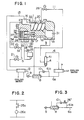
- Fig. 1 is a block diagram of a refrigeration cycle incorporating an embodiment of a refrigerant gas injection system in accordance with the invention ;
- Fig. 2 is an electric wiring diagram ;
- Fig. 3 is a block diagram of a refrigeration cycle incorporating another embodiment of the refrigerant gas injection system ; and
- Fig. 4 is a block diagram of a refrigeration cycle incorporating still another embodiment of the refrigerant gas injection system.
- Referring to Fig. 1, a refrigeration cycle incorporates a screw compressor having a casing 1 which rotatably accommodates a pair of
screw rotors 2 one of which is drivingly connected to a driving motor (not shown). Adischarge pipe 3 is connected to the casing 1 so as to communicate with adischarge chamber 31 through adischarge port 15. Anoil separator 4 is connected to thedischarge pipe 3. Theupper space 41 in theoil separator 4 is communicated with thecondenser 7 through adischarge gas pipe 6. Areference numeral 6a denotes a refrigerant liquid pipe which is connected at its one end to the refrigerant outlet of thecondenser 7, while the other end is connected to a subcooling device (referred to as an « economizer », hereinunder) which is denoted by a numeral 8. A main expansion valve 9 as a pressure reducing means is connected to the outlet side of the economizer 8. Areference numeral 10 designates an auxiliary expansion valve which is connected to a branch pipe branching from the refrigerantliquid pipe 6a. The outlet of theauxiliary expansion valve 10 is connected to the economizer 8 so that the refrigerant expanded through theauxiliary expansion valve 10 subcools the refrigerant liquid which flows through the economizer 8. Anevaporator 12 is connected at its inlet side to the main expansion valve 9 and at its outlet side to asuction chamber 32 of the screw compressor through thesuction pipe 13 past thesuction port 14. - A reference numeral 11 designates a gas introduction pipe which is connected at its one end to the outlet side of the economizer 8. The other end of the gas introduction pipe 11 leads to a
gas injection port 20 formed in the casing 1 through a gasinjection solenoid valve 26. Thegas injection port 20 is so positioned that it can communicates with the compression chamber which is in its compression process. Aslide valve 16, which constitutes an unloading means, is integrated with apiston 17a through apiston rod 17. Thepiston 17a is slidably received in acylinder 18. Thepiston 17a is urged by aspring 27 so that theslide valve 16 is kept opened while a pressure balance is maintained in the screw compressor during operation thereof. Thus, thepiston rod 17,piston 17a,spring 27 and thecylinder 18 in combination constitute an actuator for actuating theslide valve 16. The arrangement is such that, when theslide valve 16. is opened to unload the screw compressor, a part of the compressed refrigerant gas is relieved into aspace 28 which leads to the low-pressure side of the compressor, whereby the amount of the gas finally compressed is decreased. - The space in the
cylinder 18 is divided by thepiston 17a into two sections : namely, acylinder chamber 18 which is on the left side of thepiston 17a as viewed in Fig. 1 and aback chamber 18b which is on the right side of thepiston 17a. A reference numeral 19 denotes a capacity detecting hole which is formed in the wall of thecylinder 18 at a position where thepiston 17a is located when the screw compressor is operating at 100 % capacity or load. A pressure switch 25 is connected to the capacity detection hole 19 through a pressure detection pipe 29, so as to be opened and closed in response to a change in the pressure within theback chamber 18b within the cylinder. The pressure switch 25 is electrically connected to the gasinjection solenoid valve 26 in series thereto. The arrangement is such, when the contactor 25a of the pressure switch 25 makes contact, thesolenoid coil 26c of the gasinjection solenoid valve 26 is energized to open thesolenoid valve 26. - An
oil supply port 24 is formed in the wall of thecylinder 18 in such a manner as to open to thecylinder 18a. Anoil supply passage 5 leading from the oil well in theoil separator 4 and having an oilsupply solenoid valve 21 is connected to theoil supply port 24. - A
branch oil passage 51 branches from a portion of theoil supply passage 5 between theoil supply port 24 and the oilsupply solenoid valve 21. The branch oil pipe is communicated with aport 23 formed in the suction side of the casing 1 through a low-pressure equalizer valve 22. Areference numeral 30 denotes a port which is communicated with achamber 33 which in turn is connected to theback chamber 18b. Theport 30 is connected through anequalizer passage 34 to theoil branch passage 51 leading to theport 23 and, therefore, is always held in communication with the low-pressure side. Areference numeral 35 designates a stopper portion which stops thepiston 17a when thepiston 17a has been fully moved to the right as viewed in Fig. 1, thus limiting the rightward stroking of thepiston 17a. - The operation of the refrigeration cycle is as follows. The refrigerant gas sucked into the screw compressor is compressed to a high pressure and temperature, and is introduced through the
discharge pipe 3 into theoil separator 4 where the oil suspended by the refrigerant gas is separated from the oil. The separated oil is supplied through theoil supply pipe 5 to the portions of the screw compressor which need the lubrication. - On the other hand, the refrigerant gas which is now free of the oil is introduced into the
condenser 7 through thedischarge pipe 6. The refrigerant is then condensed into a liquid phase as a result of heat exchange with cooling water which is supplied to and discharged from the.condenser 7 as indicated by broken-line arrows. The refrigerant liquid thus obtained is then introduced to the main expansion valve 9 through the economizer 8. - On the other hand, the refrigerant gas expanded through the
auxiliary expansion valve 10 is made to flow through the economizer 8 so as to subcool the refrigerant liquid flowing therethrough and is returned to the compression chamber of the screw compressor in a compression process through the gas introduction pipe 11. Meanwhile, the refrigerant which has been expanded to lower pressure through the main expansion valve 9 is evaporated in theevaporator 12 through heat exchange with water which flows into and out of theevaporator 12 as indicated by broken-line arrows. The gaseous refrigerant of low pressure and temperature thus formed is then returned to thescrew compressor 13 through thesuction pipe 13. The refrigerant is thus recirculated through the refrigeration cycle while changing its phase between the liquid and gaseous phases. - The advantage of the economizer cycle having the described construction resides in that the enthalpy possessed by the refrigerant and, hence, the refrigeration power of the refrigeration cycle is increased as the extent of subcooling effected in the economizer 8 is increased, and also in that the refrigerant gas expanded through the
auxiliary expansion valve 10 and subcooled the refrigerant liquid is returned to the compression changer of the screw compressor in the compression phase so as to avoid reduction in the refrigeration power. - The control of the capacity of the screw compressor is conducted in the following manner. The level of the refrigeration load is detected through sensing the refrigerant pressure at the suction side of the compressor or the temperature of the cooling water at the outlet of the evaporator. In response to the load detection signal, the oil
supply solenoid valve 21 is opened, while the low-pressureequalizer solenoid valve 22 is closed, respectively, so that a pressurized oil is supplied into thecylinder chamber 18a on the left side of thepiston 17a. In consequence, thepiston 17a is slided to the right as viewed in Fig. 1 so as to unload the compressor thereby reducing the capacity of the screw compressor. Conversely, when thesolenoid valves cylinder chamber 18a so that thepiston 17a is slided to the left as viewed in Fig. 1 thereby, increasing the capacity. The amount of movement of thepiston 17a is controlled by the opening periods of thesolenoid valves cylinder chamber 18a on the left side of thepiston 17a is a high-pressure chamber, while theback chamber 18b on the right side of the same is a low-pressure chamber. Therefore, the capacity detection hole 19 is formed at such a position that the pressure therein is changed from the high pressure to the low pressure when thepiston 17a is moved to the position corresponding to 100 % load or capacity, as shown in Fig. 1. - This pressure change is detected and changed into an electric signal by the pressure switch 25. The gas
injection solenoid valve 26 provided in the gas introduction pipe 11 is controlled in accordance with this electric signal. Namely, when the screw compressor is operating at 100 % capacity or load level, it turns the gasinjection solenoid valve 26 on thereby activating the economizer cycle, whereby the refrigerant gas from the economizer 8 is introduced to thegas injection port 20 and injected into the compression chamber of the screw compressor. However, when the screw compressor is operating at the other load level, i. e., in the unloaded state, the gasinjection solenoid valve 26 is turned off to stop the injection of the refrigerant gas. - As will be understood from the foregoing description, according to the invention, the injection of the gas to the suction side is automatically stopped when the screw compressor is unloaded, so that the advantage of the economizer can be fully utilized without the risk of introduction of the refrigerant to the low pressure side. In the described embodiment, the 100 % capacity or load level is detected by sensing a change in the pressure. This detection system enables the invention to be applied easily to a refrigeration system employing a compressor such as a hermetic screw compressor with which it is generally difficult to find a change in the capacity or load level.
- Fig. 3 shows a modification in which the gas injection solenoid valve 26' for introducing the refrigerant gas is disposed in a pipe 61 a which is upstream of the
auxiliary expansion valve 10. It will be clear that this modification produces the same advantage as that produced in the embodiment shown in Fig. 1. - The capacity control by the slide valve can be broadly sorted into two types: namely, stepped type control and linear type control. The embodiment described hereinbefore employs the linear type control with which it is generally difficult to detect the 100 % capacity operation of the compressor.
- Another embodiment of the invention in which the compressor employs the stepped type control will be described hereinunder with reference to Fig. 4. In this Figure, the same reference numerals are used to denote the same parts or members as those appearing in Fig. 1, and detailed description of such parts or members is omitted.
- This embodiment employs an
oil supply passage 100 which is connected at its one end to the oil reservoir of theoil separator 4, while the other end is connected to theoil supply port 24 of the casing 1. An oilsupply solenoid valve 127 provided in anoil passage 102 is controlled in such a manner as to open when the compressor is operating at 100 % capacity or load level, while an unloadingsolenoid valve 128 provided in an unloading oil passage 101 is controlled in such a manner as to open when the load capacity is about 50 %. Areference numeral 190 designates a port which is formed at a position corresponding to the 50 % capacity operation. When the screw compressor is operating at 100 % load level, the oilsupply solenoid valve 127 is opened so as to relieve the oil to the low-pressure side. At the same time, the unloadsolenoid valve 128 is closed and the gasinjection solenoid valve 26 in the gas introduction pipe 11 is opened. In contrast, when the screw compressor is operating at 50 % capacity or load level, theoil supply valve 127 is closed to cause a movement of thepiston 17a so as to open theslide valve 16, while opening the unloadsolenoid valve 128, thereby relieving a part of the oil to the low-pressure side. In consequence, thepiston 17a is stably held at the position near thehole 190, so that the compressor stably operates in the unloaded state. The gas injection solenoid valve 126 is controlled in relation to the control of thesolenoid valves - In the embodiments described hereinbefore, the detection means for detecting the change in the pressure in the actuator for actuating the slide valve is constituted by the capacity detection hole 19 formed in the wall of the
cylinder 18 and the pressure switch 25. This, however, is not exclusive and the change in the pressure can be detected by the other suitable means such as an external mechanical contact means which operates externally of the compressor in response to the movement of thepiston 17a.
Claims (1)
- Refrigerant gas injection system for a refrigeration cycle, said system having a screw compressor provided with a slide valve (16) for controlling the compression capacity of said screw compressor, a condenser (7) and an economizer (8) disposed in a passage (6a) connected to a refrigerant liquid outlet of the condenser (7) and adapted for subcooling said refrigerant liquid by the refrigerant of a reduced pressure, and a refrigerant gas injection line (11) through which the refrigerant gas generated in said economizer (8) is injected into the compression chamber of said screw compressor in its compression phase, characterized by an oil supplying valve (21) disposed in an oil passage communicated with an oil supplying passage (5) and operated in response to the detection signal of a refrigerant pressure at the suction side of said screw compressor or the temperature of the cooling water at the outlet of an evaporator in such a manner that pressurized oil is supplied to actuators (17, 17a, 27, 18) for actuating said slide valve (16) to bring said screw compressor from a full load level to the unloaded state and vice versa; and a gas injection solenoid valve (26) disposed in said gas injection line (11) and operated in response to the detection signal of the pressure at said actuator (18), so that said solenoid valve (26) operates in relation to the operation of said oil supplying means (21) in such a manner as to open when said screw compressor is operating at full load level and to close when the same is operating in the unloaded state.
Applications Claiming Priority (2)
| Application Number | Priority Date | Filing Date | Title |
|---|---|---|---|
| JP105804/85 | 1985-05-20 | ||
| JP60105804A JPS61265381A (en) | 1985-05-20 | 1985-05-20 | Gas injector for screw compressor |
Publications (2)
| Publication Number | Publication Date |
|---|---|
| EP0203477A1 EP0203477A1 (en) | 1986-12-03 |
| EP0203477B1 true EP0203477B1 (en) | 1989-08-09 |
Family
ID=14417297
Family Applications (1)
| Application Number | Title | Priority Date | Filing Date |
|---|---|---|---|
| EP86106673A Expired EP0203477B1 (en) | 1985-05-20 | 1986-05-15 | Refrigerant gas injection system for refrigeration cycle having a screw compressor |
Country Status (4)
| Country | Link |
|---|---|
| US (1) | US4727725A (en) |
| EP (1) | EP0203477B1 (en) |
| JP (1) | JPS61265381A (en) |
| DE (1) | DE3664958D1 (en) |
Cited By (5)
| Publication number | Priority date | Publication date | Assignee | Title |
|---|---|---|---|---|
| US8924311B2 (en) | 2009-10-15 | 2014-12-30 | World's Fresh Waters Pte. Ltd. | Method and system for processing glacial water |
| US9010261B2 (en) | 2010-02-11 | 2015-04-21 | Allen Szydlowski | Method and system for a towed vessel suitable for transporting liquids |
| US9017123B2 (en) | 2009-10-15 | 2015-04-28 | Allen Szydlowski | Method and system for a towed vessel suitable for transporting liquids |
| US9371114B2 (en) | 2009-10-15 | 2016-06-21 | Allen Szydlowski | Method and system for a towed vessel suitable for transporting liquids |
| US9521858B2 (en) | 2005-10-21 | 2016-12-20 | Allen Szydlowski | Method and system for recovering and preparing glacial water |
Families Citing this family (69)
| Publication number | Priority date | Publication date | Assignee | Title |
|---|---|---|---|---|
| JPS6338697A (en) * | 1986-08-04 | 1988-02-19 | Mitsubishi Electric Corp | Rotary compressor |
| JPS6412092A (en) * | 1987-07-01 | 1989-01-17 | Kobe Steel Ltd | Vacuum pump of screw type |
| US4832068A (en) * | 1987-12-21 | 1989-05-23 | American Standard Inc. | Liquid/gas bypass |
| SE461346B (en) * | 1988-06-17 | 1990-02-05 | Svenska Rotor Maskiner Ab | ROTATE COMPRESSOR COMPRESSOR AND A REFRIGERATOR, A COMPRESSOR OF THE ABOVE TYPE NOT INCLUDED |
| US5095086A (en) * | 1990-08-08 | 1992-03-10 | General Electric Company | Scuff-masking coatings for glass articles |
| JPH07107395B2 (en) * | 1990-11-06 | 1995-11-15 | 本田技研工業株式会社 | Screw type pump |
| US5167130A (en) * | 1992-03-19 | 1992-12-01 | Morris Jr William F | Screw compressor system for reverse cycle defrost having relief regulator valve and economizer port |
| EP0564123A1 (en) * | 1992-04-02 | 1993-10-06 | Carrier Corporation | Refrigeration system |
| DE69414415T2 (en) * | 1994-02-03 | 1999-06-10 | Svenska Rotor Maskiner Ab, Stockholm | REFRIGERATION SYSTEM AND METHOD FOR CONTROLLING THE REFRIGERATION PERFORMANCE OF SUCH A SYSTEM |
| DE4439780A1 (en) * | 1994-11-07 | 1996-05-09 | Sep Tech Studien | Compressor chiller |
| DE19724643A1 (en) * | 1997-06-11 | 1998-12-17 | Sihi Gmbh & Co Kg | Screw compressor and method of operating the same |
| SE510066C2 (en) * | 1997-08-25 | 1999-04-12 | Svenska Rotor Maskiner Ab | Oil-free screw rotor machine, the bearings of which are lubricated with an aqueous liquid |
| US6206652B1 (en) | 1998-08-25 | 2001-03-27 | Copeland Corporation | Compressor capacity modulation |
| CN1111689C (en) * | 1997-11-17 | 2003-06-18 | 大金工业株式会社 | Refrigerating apparatus |
| JP3985384B2 (en) * | 1998-09-24 | 2007-10-03 | 株式会社デンソー | Refrigeration cycle equipment |
| DE19935041A1 (en) * | 1999-07-26 | 2001-02-08 | Bitzer Kuehlmaschinenbau Gmbh | Screw compressor |
| US6428284B1 (en) * | 2000-03-16 | 2002-08-06 | Mobile Climate Control Inc. | Rotary vane compressor with economizer port for capacity control |
| US6302668B1 (en) * | 2000-08-23 | 2001-10-16 | Fu Sheng Industrial Co., Ltd. | Capacity regulating apparatus for compressors |
| WO2004051089A1 (en) * | 2002-12-03 | 2004-06-17 | Bitzer Kühlmaschinenbau Gmbh | Screw compressor |
| ES2235681T3 (en) * | 2003-07-18 | 2010-08-31 | Star Refrigeration Ltd. | IMPROVED TRANSCRITICAL COOLING CYCLE. |
| WO2005061900A1 (en) * | 2003-12-22 | 2005-07-07 | Mitsubishi Denki Kabushiki Kaisha | Screw compressor |
| EP1851415B1 (en) * | 2005-02-24 | 2016-07-27 | Carrier Corporation | Compressor unloading valve |
| ITVI20050272A1 (en) * | 2005-10-14 | 2007-04-15 | Refcomp Spa | VOLUMETRIC COMPRESSOR WITH PERFECT SCREW |
| US20070251256A1 (en) * | 2006-03-20 | 2007-11-01 | Pham Hung M | Flash tank design and control for heat pumps |
| US7647790B2 (en) * | 2006-10-02 | 2010-01-19 | Emerson Climate Technologies, Inc. | Injection system and method for refrigeration system compressor |
| US8769982B2 (en) * | 2006-10-02 | 2014-07-08 | Emerson Climate Technologies, Inc. | Injection system and method for refrigeration system compressor |
| US8181478B2 (en) * | 2006-10-02 | 2012-05-22 | Emerson Climate Technologies, Inc. | Refrigeration system |
| US7771178B2 (en) * | 2006-12-22 | 2010-08-10 | Emerson Climate Technologies, Inc. | Vapor injection system for a scroll compressor |
| US8157538B2 (en) | 2007-07-23 | 2012-04-17 | Emerson Climate Technologies, Inc. | Capacity modulation system for compressor and method |
| WO2009045187A1 (en) * | 2007-10-01 | 2009-04-09 | Carrier Corporation | Screw compressor pulsation damper |
| CA2749562C (en) | 2009-01-27 | 2014-06-10 | Emerson Climate Technologies, Inc. | Unloader system and method for a compressor |
| US8539785B2 (en) | 2009-02-18 | 2013-09-24 | Emerson Climate Technologies, Inc. | Condensing unit having fluid injection |
| US7988433B2 (en) | 2009-04-07 | 2011-08-02 | Emerson Climate Technologies, Inc. | Compressor having capacity modulation assembly |
| US11584483B2 (en) | 2010-02-11 | 2023-02-21 | Allen Szydlowski | System for a very large bag (VLB) for transporting liquids powered by solar arrays |
| JP5358608B2 (en) * | 2011-03-30 | 2013-12-04 | 日立アプライアンス株式会社 | Screw compressor and chiller unit using the same |
| US10378533B2 (en) | 2011-12-06 | 2019-08-13 | Bitzer Us, Inc. | Control for compressor unloading system |
| US9651043B2 (en) | 2012-11-15 | 2017-05-16 | Emerson Climate Technologies, Inc. | Compressor valve system and assembly |
| US9249802B2 (en) | 2012-11-15 | 2016-02-02 | Emerson Climate Technologies, Inc. | Compressor |
| US9435340B2 (en) | 2012-11-30 | 2016-09-06 | Emerson Climate Technologies, Inc. | Scroll compressor with variable volume ratio port in orbiting scroll |
| US9127677B2 (en) | 2012-11-30 | 2015-09-08 | Emerson Climate Technologies, Inc. | Compressor with capacity modulation and variable volume ratio |
| CN105579709B (en) | 2013-10-01 | 2018-05-04 | 特灵国际有限公司 | Rotary compressor with variable speed and volume control |
| US9739277B2 (en) | 2014-05-15 | 2017-08-22 | Emerson Climate Technologies, Inc. | Capacity-modulated scroll compressor |
| US9989057B2 (en) | 2014-06-03 | 2018-06-05 | Emerson Climate Technologies, Inc. | Variable volume ratio scroll compressor |
| US9790940B2 (en) | 2015-03-19 | 2017-10-17 | Emerson Climate Technologies, Inc. | Variable volume ratio compressor |
| US10378540B2 (en) | 2015-07-01 | 2019-08-13 | Emerson Climate Technologies, Inc. | Compressor with thermally-responsive modulation system |
| WO2017027657A1 (en) * | 2015-08-11 | 2017-02-16 | Carrier Corporation | Screw compressor economizer plenum for pulsation reduction |
| CN207377799U (en) | 2015-10-29 | 2018-05-18 | 艾默生环境优化技术有限公司 | Compressor |
| CN105910339B (en) * | 2016-06-08 | 2017-12-08 | 郑州轻工业学院 | A kind of double-screw compressor superfeed pressure control system and method |
| US10890186B2 (en) | 2016-09-08 | 2021-01-12 | Emerson Climate Technologies, Inc. | Compressor |
| US10801495B2 (en) | 2016-09-08 | 2020-10-13 | Emerson Climate Technologies, Inc. | Oil flow through the bearings of a scroll compressor |
| US10753352B2 (en) | 2017-02-07 | 2020-08-25 | Emerson Climate Technologies, Inc. | Compressor discharge valve assembly |
| US10808699B2 (en) | 2017-09-28 | 2020-10-20 | Ingersoll-Rand Industrial U.S., Inc. | Suction side slide valve for a screw compressor |
| US11022119B2 (en) | 2017-10-03 | 2021-06-01 | Emerson Climate Technologies, Inc. | Variable volume ratio compressor |
| US10962008B2 (en) | 2017-12-15 | 2021-03-30 | Emerson Climate Technologies, Inc. | Variable volume ratio compressor |
| US10995753B2 (en) | 2018-05-17 | 2021-05-04 | Emerson Climate Technologies, Inc. | Compressor having capacity modulation assembly |
| JP7146478B2 (en) * | 2018-06-22 | 2022-10-04 | 株式会社神戸製鋼所 | Screw compressor and gas compression system |
| JP7282561B2 (en) * | 2019-03-27 | 2023-05-29 | 株式会社日立産機システム | LIQUID-COOLED GAS COMPRESSOR AND LIQUID SUPPLY METHOD THEREOF |
| CN110274403A (en) * | 2019-06-26 | 2019-09-24 | 太原理工大学 | The quasi- two-stage compression circulation system of injector synergy |
| CN110274402A (en) * | 2019-06-26 | 2019-09-24 | 太原理工大学 | The heating of quasi- two-stage compression and the refrigerating integrated system of injector synergy |
| US11629894B2 (en) * | 2020-01-10 | 2023-04-18 | Johnson Controls Tyco IP Holdings LLP | Economizer control systems and methods |
| US11655813B2 (en) | 2021-07-29 | 2023-05-23 | Emerson Climate Technologies, Inc. | Compressor modulation system with multi-way valve |
| CN113982916A (en) * | 2021-09-18 | 2022-01-28 | 江森自控空调冷冻设备(无锡)有限公司 | Compressor |
| US12259163B2 (en) | 2022-06-01 | 2025-03-25 | Copeland Lp | Climate-control system with thermal storage |
| US11846287B1 (en) | 2022-08-11 | 2023-12-19 | Copeland Lp | Scroll compressor with center hub |
| US11965507B1 (en) | 2022-12-15 | 2024-04-23 | Copeland Lp | Compressor and valve assembly |
| US12416308B2 (en) | 2022-12-28 | 2025-09-16 | Copeland Lp | Compressor with shutdown assembly |
| US12173708B1 (en) | 2023-12-07 | 2024-12-24 | Copeland Lp | Heat pump systems with capacity modulation |
| US12163523B1 (en) | 2023-12-15 | 2024-12-10 | Copeland Lp | Compressor and valve assembly |
| JP7716465B2 (en) * | 2023-12-20 | 2025-07-31 | 日立ジョンソンコントロールズ空調株式会社 | Screw compressor and refrigeration cycle device |
Family Cites Families (11)
| Publication number | Priority date | Publication date | Assignee | Title |
|---|---|---|---|---|
| US3081604A (en) * | 1959-05-28 | 1963-03-19 | Carrier Corp | Control mechanism for fluid compression means |
| FR1566954A (en) * | 1968-05-22 | 1969-05-09 | ||
| US3827250A (en) * | 1973-07-23 | 1974-08-06 | Carrier Corp | Economizer pressure regulating system |
| US4005949A (en) * | 1974-10-10 | 1977-02-01 | Vilter Manufacturing Corporation | Variable capacity rotary screw compressor |
| GB1548663A (en) * | 1975-06-24 | 1979-07-18 | Maekawa Seisakusho Kk | Refrigerating apparatus |
| DE2618440A1 (en) * | 1976-04-27 | 1977-11-10 | Sullair Europ Corp | METHOD AND DEVICE FOR CONTROLLING THE OPERATION OF A COMPRESSOR |
| US4171188A (en) * | 1976-08-03 | 1979-10-16 | Chicago Pneumatic Tool Company | Rotary air compressors with intake valve control and lubrication system |
| DE2648609A1 (en) * | 1976-10-27 | 1978-05-03 | Linde Ag | METHOD AND DEVICE FOR COOLING AN OIL-FLOODED COMPRESSOR |
| US4249866A (en) * | 1978-03-01 | 1981-02-10 | Dunham-Bush, Inc. | Control system for screw compressor |
| JPS5582262A (en) * | 1978-12-18 | 1980-06-20 | Ebara Mfg | Screw refrigerating machine |
| JPS59119084A (en) * | 1982-12-24 | 1984-07-10 | Hitachi Ltd | Capacity controlling apparatus for screw compressor |
-
1985
- 1985-05-20 JP JP60105804A patent/JPS61265381A/en active Granted
-
1986
- 1986-05-14 US US06/863,245 patent/US4727725A/en not_active Expired - Lifetime
- 1986-05-15 EP EP86106673A patent/EP0203477B1/en not_active Expired
- 1986-05-15 DE DE8686106673T patent/DE3664958D1/en not_active Expired
Cited By (5)
| Publication number | Priority date | Publication date | Assignee | Title |
|---|---|---|---|---|
| US9521858B2 (en) | 2005-10-21 | 2016-12-20 | Allen Szydlowski | Method and system for recovering and preparing glacial water |
| US8924311B2 (en) | 2009-10-15 | 2014-12-30 | World's Fresh Waters Pte. Ltd. | Method and system for processing glacial water |
| US9017123B2 (en) | 2009-10-15 | 2015-04-28 | Allen Szydlowski | Method and system for a towed vessel suitable for transporting liquids |
| US9371114B2 (en) | 2009-10-15 | 2016-06-21 | Allen Szydlowski | Method and system for a towed vessel suitable for transporting liquids |
| US9010261B2 (en) | 2010-02-11 | 2015-04-21 | Allen Szydlowski | Method and system for a towed vessel suitable for transporting liquids |
Also Published As
| Publication number | Publication date |
|---|---|
| JPH0324595B2 (en) | 1991-04-03 |
| EP0203477A1 (en) | 1986-12-03 |
| US4727725A (en) | 1988-03-01 |
| DE3664958D1 (en) | 1989-09-14 |
| JPS61265381A (en) | 1986-11-25 |
Similar Documents
| Publication | Publication Date | Title |
|---|---|---|
| US4727725A (en) | Gas injection system for screw compressor | |
| JP3321191B2 (en) | refrigerator | |
| EP1605167B1 (en) | Rotary sealed compressor and refrigeration cycle apparatus | |
| US5243827A (en) | Overheat preventing method for prescribed displacement type compressor and apparatus for the same | |
| US3795117A (en) | Injection cooling of screw compressors | |
| KR930002429B1 (en) | Refrigeration cycle equipment | |
| USRE30499E (en) | Injection cooling of screw compressors | |
| US5157943A (en) | Refrigeration system including capillary tube/suction line heat transfer | |
| US4084405A (en) | Refrigerating system | |
| US5140828A (en) | Refrigeration cycle apparatus | |
| JPH06229634A (en) | Freezer | |
| JPH03129255A (en) | Refrigeration equipment | |
| EP0564123A1 (en) | Refrigeration system | |
| JPS59191855A (en) | Refrigerator | |
| KR910000678B1 (en) | Refrigeration cycle device | |
| JP3334331B2 (en) | Air conditioner | |
| JP2011237127A (en) | Refrigerating device | |
| JP3182188B2 (en) | Refrigeration equipment | |
| JPH05187378A (en) | Screw compressor capacity controller | |
| JPH0439574A (en) | Refrigerating device | |
| KR0135133B1 (en) | Evaporator structure for cooler with double evaporators | |
| JPS6029555A (en) | Refrigeration cycle of 2 cylinder rotary compressor | |
| JPH0439576A (en) | Refrigerating device | |
| JP2002081773A (en) | Helium compressor unit | |
| JPS5818138Y2 (en) | refrigeration cycle |
Legal Events
| Date | Code | Title | Description |
|---|---|---|---|
| PUAI | Public reference made under article 153(3) epc to a published international application that has entered the european phase |
Free format text: ORIGINAL CODE: 0009012 |
|
| 17P | Request for examination filed |
Effective date: 19860515 |
|
| AK | Designated contracting states |
Kind code of ref document: A1 Designated state(s): DE GB |
|
| 17Q | First examination report despatched |
Effective date: 19880202 |
|
| GRAA | (expected) grant |
Free format text: ORIGINAL CODE: 0009210 |
|
| AK | Designated contracting states |
Kind code of ref document: B1 Designated state(s): DE GB |
|
| REF | Corresponds to: |
Ref document number: 3664958 Country of ref document: DE Date of ref document: 19890914 |
|
| PLBE | No opposition filed within time limit |
Free format text: ORIGINAL CODE: 0009261 |
|
| STAA | Information on the status of an ep patent application or granted ep patent |
Free format text: STATUS: NO OPPOSITION FILED WITHIN TIME LIMIT |
|
| 26N | No opposition filed | ||
| PGFP | Annual fee paid to national office [announced via postgrant information from national office to epo] |
Ref country code: DE Payment date: 19920729 Year of fee payment: 7 |
|
| PG25 | Lapsed in a contracting state [announced via postgrant information from national office to epo] |
Ref country code: DE Effective date: 19940201 |
|
| REG | Reference to a national code |
Ref country code: GB Ref legal event code: IF02 |
|
| PGFP | Annual fee paid to national office [announced via postgrant information from national office to epo] |
Ref country code: GB Payment date: 20040428 Year of fee payment: 19 |
|
| PG25 | Lapsed in a contracting state [announced via postgrant information from national office to epo] |
Ref country code: GB Free format text: LAPSE BECAUSE OF NON-PAYMENT OF DUE FEES Effective date: 20050515 |
|
| GBPC | Gb: european patent ceased through non-payment of renewal fee |
Effective date: 20050515 |