EP0203456A2 - Electric control mirror apparatus - Google Patents
Electric control mirror apparatus Download PDFInfo
- Publication number
- EP0203456A2 EP0203456A2 EP86106547A EP86106547A EP0203456A2 EP 0203456 A2 EP0203456 A2 EP 0203456A2 EP 86106547 A EP86106547 A EP 86106547A EP 86106547 A EP86106547 A EP 86106547A EP 0203456 A2 EP0203456 A2 EP 0203456A2
- Authority
- EP
- European Patent Office
- Prior art keywords
- mirror
- housing member
- housing
- mirror body
- members
- Prior art date
- Legal status (The legal status is an assumption and is not a legal conclusion. Google has not performed a legal analysis and makes no representation as to the accuracy of the status listed.)
- Granted
Links
Images


Classifications
-
- B—PERFORMING OPERATIONS; TRANSPORTING
- B60—VEHICLES IN GENERAL
- B60R—VEHICLES, VEHICLE FITTINGS, OR VEHICLE PARTS, NOT OTHERWISE PROVIDED FOR
- B60R1/00—Optical viewing arrangements; Real-time viewing arrangements for drivers or passengers using optical image capturing systems, e.g. cameras or video systems specially adapted for use in or on vehicles
- B60R1/02—Rear-view mirror arrangements
- B60R1/06—Rear-view mirror arrangements mounted on vehicle exterior
- B60R1/062—Rear-view mirror arrangements mounted on vehicle exterior with remote control for adjusting position
- B60R1/07—Rear-view mirror arrangements mounted on vehicle exterior with remote control for adjusting position by electrically powered actuators
- B60R1/072—Rear-view mirror arrangements mounted on vehicle exterior with remote control for adjusting position by electrically powered actuators for adjusting the mirror relative to its housing
-
- F—MECHANICAL ENGINEERING; LIGHTING; HEATING; WEAPONS; BLASTING
- F16—ENGINEERING ELEMENTS AND UNITS; GENERAL MEASURES FOR PRODUCING AND MAINTAINING EFFECTIVE FUNCTIONING OF MACHINES OR INSTALLATIONS; THERMAL INSULATION IN GENERAL
- F16C—SHAFTS; FLEXIBLE SHAFTS; ELEMENTS OR CRANKSHAFT MECHANISMS; ROTARY BODIES OTHER THAN GEARING ELEMENTS; BEARINGS
- F16C11/00—Pivots; Pivotal connections
- F16C11/04—Pivotal connections
- F16C11/06—Ball-joints; Other joints having more than one degree of angular freedom, i.e. universal joints
- F16C11/0661—Ball-joints; Other joints having more than one degree of angular freedom, i.e. universal joints the two co-operative parts each having both convex and concave interfaces
-
- Y—GENERAL TAGGING OF NEW TECHNOLOGICAL DEVELOPMENTS; GENERAL TAGGING OF CROSS-SECTIONAL TECHNOLOGIES SPANNING OVER SEVERAL SECTIONS OF THE IPC; TECHNICAL SUBJECTS COVERED BY FORMER USPC CROSS-REFERENCE ART COLLECTIONS [XRACs] AND DIGESTS
- Y10—TECHNICAL SUBJECTS COVERED BY FORMER USPC
- Y10S—TECHNICAL SUBJECTS COVERED BY FORMER USPC CROSS-REFERENCE ART COLLECTIONS [XRACs] AND DIGESTS
- Y10S248/00—Supports
- Y10S248/90—Movable or disengageable on impact or overload
Definitions
- the present invention relates to an electrically driven remote-controlled mirror apparatus used for an automobile, more particularly to a mirror apparatus which is designed such that a driver of the automobile can remotely control the rotation of a mirror mounted on the automobile at the driver's seat in order to obtain a rear vision and side visions suitably.
- U.S.Patent No. 4, 076,392 discloses a remote control mirror apparatus in which there is provided an axial bore on a block having a ball portion of the end point portion thereof and a pin having a screw portion rotatably supported on a casing, and the screw poriton is disposed within the axial bore and the block has a needle contacting to the screw portion of the pin.
- U.S.Patent No. 4,324,454 discloses a remote control mirror apparatus in which there is provided three catches at the end portion of a hollow- cylindrical adjusting nut having a ball portion at the end point thereof and each of the catches is in pressing contact with the bottom portion of a male screw portion of the adjusting member.
- the adjusting nut is adapted to effect an axial movement by rotating the male screw portion of the adjusting member.
- the adjusting member per se is adapted to effect a conically swing on a root, therefore a pressing contact force required for contacting the three catches of the adjusting nut with the male screw portion of the adjusting member is undesirably moving the adjusting nut in the direction perpendicular to the axial direction.
- the object of the present invention is to present an electric remote control mirror apparatus in which the disadvantages of the above-mentioned conventional remote control mirror apparatus are deviscome.
- Another object of the present invention is to present an electric remote control mirror apparatus in which a pair of screw rods for slanting a mirror is stably supported and a smooth axial movement thereof can be achieved.
- Another object of the present invention is to present an electric remote control mirror apparatus in which a sealing between a screw rod and a drive case for receiving each screw rod in a free-movable state is surely obtained within a region of dgree of freedom of a pair of screw rods for slanting a mirror.
- Another object of the present invention is to present an electric remote control mirror apparatus in which upon an axial movement of a pair of screw rods for slanting a mirrir, the axial movement is surely maintained even when an external force such as a vibration is applied thereto.
- Still a further object of the present invention is to present an electric remote control mirror apparatus in which there is provided a pivot connection mechanism which is designed to provide a uniform rotation resistance and to be automatically fabricated very easily.
- FIG. 1 to 8 a constitution of an embodiment of the electric remote control mirror apparatus of the present invention is shown.
- Fig. 1 showing a sectional view of the remote control apparatus mir r o r/ ,numerals 30 and 30a designate a mirror body and a mirror to be fixed to the mirror body, respectively.
- the mirror body 30 is fixed in a mirror housing 31 and is supported rotatably with respect to a drive case 40 including a driving unit for rotating the mirror body 30, as mentioned hereinafter.
- the drive case 40 is formed in a cylindrical closed body and composed of an upper casing 40a and a lower casing 40b as shown in Fig. 2.
- the mirror body 30 is supported by supporting means.
- the supporting means includes a pivot connection 44 composed of a ball base 42 having a concave surface 43 formed integrally on the front surface of the upper casing 40a and a hollowed boss portion 32 having a boss surface 34 with a curvature fitting to the concave surface 43 of the ball base 42, the hollowed boss portion 32 being integrally formed on the back surface of the mirror body 30.
- a projected portion 48 in.a conical formation having a through hole 49 formed coaxially with the pivot axis of the pivot connection 44 .
- a kerf 52 for dividing the top portion of the projected portion 48 into two parts.
- a pressure applying member 46 having a boss surface which is adapted to be fitted to an inner surface 36 of the hollowed boss portion 32 of the mirror body 30, and a through hole 51 is provided at the central portion of the pressure applying member 46, the through hole 51 being formed coaxially with the through hole 49 and ..having substantially the same diameter as that of the through hole 49 of the ball base 42.
- a recess poriton to be fitted with the projected portion 48 of the ball base 42 and a rib portion 50 to be fitted with the kerf 52 as shown in Fig. 2.
- the other end of the pressure applying member 46 is formed in a plane surface and contacted to a head portion of a bolt 56 extending into the drive case 40 by passing through the through holes 51 and 49.
- a screw portion 58 of the bolt 56 has the diameter smaller than the shaft portion and is aecrewed to the screw portion 61 of a nut 60 having a substantial squar formation.
- a compression coil spring 59 is disposed around the bolt 56 and between the back surface of the upper casing 40a and the nut 60, as shown in Figs. 5 and 6. As shown in Figs.
- a box-like projection wall composed of four walls 62 projecting from the back surface of the upper casing 40a toward the lower casing 40b, the coil spring 59 being received in the box-like projection wall and the nut is also received therein such that the nut 60 can move in the axial direction of the bolt 56.
- the periphery of the nut 60 is contacted to each of walls 62 and the compression coil spring 59 is adapted to supply the resilient force to the surface of the nut 60.
- the bolt 56 is applied with the pressing force in the downward direction, whereby the pressure applying member 46 is depressed by the head portion of the bolt 56 against the inner surface 36 of the hollowed boss portion 32 of the mirror body 30 and further the boss surface 34 of the hollowed boss portion 32 of the mirror body 30 is depressed with a uniform force against the concave surface 43 of the ball base 42.
- the rib portion 50 of the pressure applying member 46 fits to the kerf 52 mounted at the bottom portion of the ball base 42, therefore the rotation of the pressure applying member 46 around the.pivot shaft is inhibited. Therefore, the hollowed boss portion 32 of the mirror bady 30 is stably supported between the ball base 42 and the pressure applying member 46 by utilizing a suitable friction force.
- the rotation resistance of the pivot connection 44 depends on the resilient force of the compression coil spring 59 and the frictional force produced between the hollowed boss portion 32 of the mirror body 30 and the pressure applying member 46 and further between the boss surface 34 of the hollowed boss portion 32 and the concave surface 43 of the ball base 42.
- the rotation resistance is suitably selected such that the mirror body 30 does not move or vibrate by an external force e.g. wind pressure or the vibration due to running of the automobile.
- the compression coil spring 59 and the nut 60 are first received within the box-like space enveloped by the four walls 62 of the upper casing 40a and then the upper casing 40a is fitted to the lower casing 40b .
- the mirror body. 30 is disposed in such a manner that the hollowed boss portion 32 of the mirror body 30 fits to the concave surface 43 of the ball base 42, and the boss surface of the pressure applying member 46 is fitted to the inner surface 36 of the hollowed boss poriton 32 of the mirror body 30 :and further the rib portion 50 is fitted to the kerf 52 of the ball base 42.
- the bolt 56 is inserted into the through hole 51 of the pressure applying member 46 and the through hole 49 located at the cental portion of the ball base 42, from the side of the mirror body 30, whereby the end point of the screw portion 58 of the belt 56 is screwed to the female screw 61 of the nut 60, as shown in Fig. 5.
- the bolt 56 is rotated in the state as shown in Fig. 5 whereby the bolt 56 is screwed into the female screw 61 of the nut 60, since the nut 60 is inhibitted to rotate by the box-like wall 62.
- the nut 60 moves in the direction of the pivot shaft namely the upward direction in Fig..5, and the compression coil spring 59 is gradually compressed.
- the surface on which the compression coil-spring 59 contacts to the nut 60 is adapted to be apart from the back surface of the upper casing 40a so as to provide the resilient force due to the coil spring 59 against the bolt 56 effectively.
- the square nut 60 is automatically mounted coaxially with the pivot shaft as a stopper of the coil spring 59 and by rotation of the bolt 56, a predetermined resilient force is easily obtained,.therefore such constitution of the pivot connection 44 is excellent in view of an automatic fabrication.
- screw rods 70 and 71 for moving or slanting the mirror body 30 in the drive case 40.
- Each screw rods 70 or 71 is drived by an electric motor 130 mounted in the drive case 40 as mentioned hereinafter.
- each of the screw rods 70 and 71 is formed in a hollowed cylinder and there is provided ball portions 72 and 73 at one end of the screw rods 70 and 71 resepctively and a female screw 74 is formed at inner surface of each screw rod 70 or 71.
- Each of the ball portions 72 and 73 . is fitted to each of the ball bases 75a and 75b formed at the back surface of the mirror body 30 respectively.
- the ball bases 75a and 75b are located on two straight liens perpendicualr to each other, i.e. x-x axis and y-y axis in Fig.4, respectively, the two straight lines being pass through the axis of the pivot connection 44.
- the mirror bosy 30 may be moved or slanted around the x-x axis or y-y axis.
- each. of the screw rods 70 and 71 moves forwardly or backwardly through an opening mounted on the upper casing 40a, the periphery surface of each of the screw rods 70 and 71 is contacted, as shwon in Fig. 1, to the inner surface of each of 0-ring 106 made of rubber material disposed at the end portion of each of the openings.
- the screw rods 70 and 71 are stably supported and any insertion of water and/or dust from an external into the drive case 40, is prevented.
- rotation members 78 each of which has a male screw 80 and the rotation memberst 78 are coaxially disposed to the screw rods 70 and 71 respectively, and the respective male screws 80 are screwed into the feamle screw 74 of the screw rods 70 and 71 resepctively.
- Each of the rotation members 78 has a pair of arm portions 81 at the end point of which the male screw 80 is provided. "The rotation member 78 is rotatably supported on the supporting shaft as shown in Fig. 1.
- the paired arm portions 81 and 81 are made of plastic material thereby providing a resilient force in the direction perpendicular to the axial direction.
- the paired arm portions 81 and 81 are disposed in an offset portion by 180° with respect to the rotation axis of the rotation members 78 and 78, namely in an opposite position with each other, and there is disposed a substantial U-shaped plate spring 90 between two arm portions 81 and 81 in order to press the male screw portions 80 and 80 against the female screw portion 74 of the screw rod 70.
- the periphery of each of the screw rods 70 and 71 is supported by the O-ring 106, and the inner surface of each of the screw roda 70 and 71 is supported by the arm portions 81 and 81.
- Numerals 84 and 84 designate gear member mounted coaxially with rotation members 78 and 78 resepctively, thereby rotating integrally with the rotation members 78 and 78 respectively.
- each of the gear members 84 and 84 Is formed in a hollowed cylinder for receiving the screw rod 70 including the arm portions 81 and 81 of the rotation member 78 therein.
- the gear member 84 there are provided three recesses 81 at the periphery thereof.
- the three recesses 81 are adapted to receive three stoppers 82 formed at the end portion of the arm portion 81 of the rotation member 78 which are extending in the radial direction, respectively.
- the rotation member 78 can be rotated together with the gear member 84.
- the other end of the gear member 84 has an enlarged-diameter portion and a spur gear 86 is provided at the periphery of the enlarged-diameter portion.
- the spur gear 86 is coupled to a worm gear 132 fixed on the output shaft of an electric motor 130 through a double-geared spur gear as shown in Fig. 3.
- the inner surface extending in the axial direction of the enlarged-diameter portion of the gear member 84 is smoothly contacted to the peripheral surface of the annular wall formed on the back surface of the upper casing 40a as shown in Fig. 1, on the other hand the inner surface 100 ( in Fig. 7 ) extending in the radial direction of the enalrged- diameter portion of the gear member 84 is smoothly contact to the surface of an annular washer member 102 as shown in Fig. 8.
- the washer member 102 has recess portion, e.g. three recess portions 104 as shown in Fgi.
- the reaess portions 104 are fitted to projected portions (not shown ), e.g. three projected protions, formed at the end of the annular wall of the upper casing 40a. Therefore the washer 102 is adapted to be inhibitted to rotate as the gear member 84 is rotated. Furthermore, as shown in Fig. 8, the other surface of the washer member 102 is contacted to the O-ring 106 having a resilient force due to a rubber material. By the resilient force of the 0-ring 106, the washer 102 is adapted to be depressed to the inner surface 100 (. Fig. 7 ) of the gear member 84.
- the gear member 84 and the washer member 102 are preferably made of the material having a small coefficient of friction such as synthetic resin.
- the washer member 102 is adapted to be fixdely held against the upper casing 40a when the gear member 84 is rotated and to affect no influence to the rotation of the gear member 84.
- the washer member 102 as well as the 0-ring 106 surely prevents the drive case 40 from an external object such as water and/or dust.
- the center axis of the cylindrical portion of the screw rod 70 ( 71 ) is offset to the center of the ball portion 72 ( 73 ), and-the screw rods 70 and 71 can move forwardly or backwardly in the axial direction as the rotation members 78 and 78 are rotated respectively.
- the ball portion 72 (73) of the screw rod 70 (71) moves in actual in a circular motion around the pivot connection 44, therefore there is provided a small gap between the inner surface of the cylindrical portion of the screw rod 70 (71) and the arm portions 81 and 81 of the rotation member 78, and further between the peripheral portion of the cylindrical portion of the screw rod 70 (71) and the inner surface of the gear member 84.
- an end portion at which the ball portion 72 (73) of the screw rod 70 (71) is mounted is provided with a projected piece 110 extending toward the center of the pivot connection 44 as shown in Figs. 2 and 7, and further there is provided a pair of projected members 112 and 112 on the upper surface of the upper casing 40a, the projected member 112 and 112 being extending in the direction parallel to the axial direction of the screw rod 70 (7.1) and the projected piece 110 being sandwiched by the paired projected members 112 and 112.
- the projected piece 110 and the paired projected member 112 there are provided a projected piece 111 and a pair of projected members 113 and 113 for the screw rod 71 and the ball portion 73 as shown in Fig. 2.
- each of the projected members 112, 112, 113, 113, 114 and 114 is positioned within an opening provided on the mirror body 30, and the end portion is contacted to each of bars 120, 121 and 122 which are integrally formed with the hollowed boss portion 32 and extending outside fo the hollowed boss portion 32 in the radial direction, i.e. in the direction of x-x axis and y-y axis as shown in Fig. 2.
- the corresponding projected piece 110 is guided by the corresponding paired projected members 112 and 112 and further the bar 120 of the mirror body 30 is supported or held by the paired projected members 112 and 112 during the slanting motion of the mirror body 30.
- the bar 121 located on the yiy axis line is restricted to move in the x-x axis direction by the paired projected members 113 and.113, therefore the mirror body 30 is prevented from moving in the x-x axis direction when the screw rod 70 is moved forwardly or backwardly, even if the mirror body 30 is affected with an external force such as vibration.
- the mirror body 30 can be slanted around the x-x axis, but the movement of the mirror body 30 around the y-y axis is restricted by the provision of the bars 120 and 122 and the projected members 112, 112, 114 and 114.
- each screw rod 70 and 71 is offset with the center of each of the ball portions 72 and 73 thereby preventing a rotation of each ball portion 72 (73) within each ball base 75a (75b).
- a rotation of each screw rod 70 (71) is surely prevented by the provision of each projected piece 110 (110) and the corresponding projected members 112 (113), therefore each screw rod 70 (71) can move forwardly or backwardly in the substantial z-z axis direction without any rotation.
- three projected members and three bars are provided in this embodiment , however the object of the arrangement can be achieved by providing only two projected members 112,112; 113 and 113 and two bars 120 and 121, or alternatively by further providing another pair of projected members oppositely to the projected members 113 and 113 with respect to the ball base 42 on the upper casing 40a and another bar on the mirror body 30 corresponding to another pair of projected members.
- rotation member 78 is formed'separetly with the gear member 84 in this embodiment, however they may be formed integrally.
- a fabricating operation of the electric remote control mirror apparatus as mentioned above is effected as follows. As shown in Fig. 3, on the back surface of the upper casing 40a, the 0-ring 106, the washer member 102, the gear member 84, the rotation member 78, the gear 134 and the motor 130 having the worm gear 132 mounted on the output shaft of the motor 130 are disposed in order, then the compression coil spring 59 and the nut 60 are disposed, an 0-ring 41 (Fig. 1) being disposed at the periphery edge of the upper casing 40a, and the lower casing 40b being fitted to the upper casing 40a.
- a pair of click members 156 and 156 formed on the side wall of the lower casing 40b are fitted to a pair of coupling members 154 and 154 formed on the side wall of the upper casing 40a respectively, thereby connecting the upper casing 40a to the lower casing 40b.
- the upper and lower casings 40a and 40b are fixed by using screw bolts 152.
- the screw rods 70 and 71 are inserted into the drive case 40 through openings mounted on the surface of the upper casing 40a respectively, in such a manner that the ball base poritons 75a and 75b of the mirror body '30 fit to the ball portions 72 and 73 of the screw rods 70 and 71 respectively and further the hollowed boss portion 32 of the mirror body 30 is fitted within the ball base 42 of the lower casing 40b.
- the screw bolt 56 is inserted through the through hole 51 of the pressure applying member 46 and the through hole 49 of the upper casing 40a. Then, the screw bolt 56 is rotated thereby screwing the male screw portion 58 of the bolt 56 to the female screw portion 61 of the nut 60, and a suitable compression force is applied to the compression coil spring 59.
Landscapes
- Engineering & Computer Science (AREA)
- General Engineering & Computer Science (AREA)
- Mechanical Engineering (AREA)
- Multimedia (AREA)
- Rear-View Mirror Devices That Are Mounted On The Exterior Of The Vehicle (AREA)
Abstract
Description
- The present invention relates to an electrically driven remote-controlled mirror apparatus used for an automobile, more particularly to a mirror apparatus which is designed such that a driver of the automobile can remotely control the rotation of a mirror mounted on the automobile at the driver's seat in order to obtain a rear vision and side visions suitably.
- In a conventional electric remote control mirror apparatus in which a rear or side vision suitable for a driver of an automobile is obtained by moving a mirror surface, there are provided a mechanism for pivotably supporting a mirror body fixing a mirror or a backing member trough a pivot connection and a mechanism for rotating the mirror body around the pivot connection in the vertical and horizontal directions.
- It is required for such conventional electric remote control mirror apparatus, to provide the mechanism including the pivot connection for pivotably and stably supporting the mirror and the mechnism for smoothly slanting the mirror around the pivot connection, and particularly to provide a pair screw rods for rotating the mirror around the vertical axis as well as the horizontal axis by using an electric motor through a reduction gear. Therefore, there is a problem that.the screw rods are not moved smoothly because each screw rod is not supported stably when it is moved forwardly or..backwardly in the state that the rotation of the screw rod is inhibited. In actual, a ball portion fixed on the end point of the screw rod, which ball portion being fitted into a ball base mounted on a.mirror base, moves circularly around the pivot connection, therefore the screw rod is given with a degree of freedom of movement to follow to the movement of the ball portion. For example, U.S.Patent No. 4, 076,392 discloses a remote control mirror apparatus in which there is provided an axial bore on a block having a ball portion of the end point portion thereof and a pin having a screw portion rotatably supported on a casing, and the screw poriton is disposed within the axial bore and the block has a needle contacting to the screw portion of the pin. By rotating the pin the block is effected with an axial movement, however the axial movement is undesirably not smooth thereby moving in the direction perpendicualr to the axial direction, because the pin contacts in a point contact to the block through the.needle.- Furthermore, U.S.Patent No. 4,324,454 discloses a remote control mirror apparatus in which there is provided three catches at the end portion of a hollow- cylindrical adjusting nut having a ball portion at the end point thereof and each of the catches is in pressing contact with the bottom portion of a male screw portion of the adjusting member. The adjusting nut is adapted to effect an axial movement by rotating the male screw portion of the adjusting member. However, the adjusting member per se is adapted to effect a conically swing on a root, therefore a pressing contact force required for contacting the three catches of the adjusting nut with the male screw portion of the adjusting member is undesirably moving the adjusting nut in the direction perpendicular to the axial direction.
- The object of the present invention is to present an electric remote control mirror apparatus in which the disadvantages of the above-mentioned conventional remote control mirror apparatus are obercome.
- Another object of the present invention is to present an electric remote control mirror apparatus in which a pair of screw rods for slanting a mirror is stably supported and a smooth axial movement thereof can be achieved.
- Another object of the present invention is to present an electric remote control mirror apparatus in which a sealing between a screw rod and a drive case for receiving each screw rod in a free-movable state is surely obtained within a region of dgree of freedom of a pair of screw rods for slanting a mirror.
- 'Another object of the present invention is to present an electric remote control mirror apparatus in which upon an axial movement of a pair of screw rods for slanting a mirrir, the axial movement is surely maintained even when an external force such as a vibration is applied thereto.
- Still a further object of the present invention is to present an electric remote control mirror apparatus in which there is provided a pivot connection mechanism which is designed to provide a uniform rotation resistance and to be automatically fabricated very easily.
- Other features, additional objects, and many of the attendant advantages of the present invention will readily be appreciated as the same becomes better understood by reference to the following detailed description of a preferred embodiment when considered in connection with the appended drawing in which:
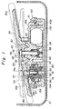
- Fig. 1 is a sectional view showing an embodiment of the electric remote control mirror apparatus of the present invention;
- Fig. 2 is a partially broken-perspective view showing a relationship in connection between a drive case and a mirror body
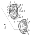
- Fig. 3 is a partially broken perspective view showing constitution elements disposed within the drive case, in which a lower casing is removed;
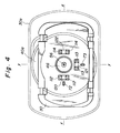
- Fig. 4 is a front view of the electric remote control mirror apparatus, in which the mirror is shown by an imagination line;
- Figs...5 and 6 are sectional views showing the connection between the mirror body and the drive case by a pivot connection;
- Fig. 7 is a partially broken enlarged view showing the relationship among a screw rod, a rotating member and a gear member;and
- Fig. 8 is a front view showing a washer member.
- Referring now to Figs. 1 to 8 a constitution of an embodiment of the electric remote control mirror apparatus of the present invention is shown.
- In Fig. 1 showing a sectional view of the remote control apparatus mirror/,
numerals mirror body 30 is fixed in amirror housing 31 and is supported rotatably with respect to adrive case 40 including a driving unit for rotating themirror body 30, as mentioned hereinafter. Thedrive case 40 is formed in a cylindrical closed body and composed of anupper casing 40a and alower casing 40b as shown in Fig. 2. There is provided a O-ring 41 between theupper casing 40a and thelower casing 40b thereby inhibiting the insertion of external object such as water and/or dust. - The
mirror body 30 is supported by supporting means. The supporting means includes apivot connection 44 composed of aball base 42 having aconcave surface 43 formed integrally on the front surface of theupper casing 40a and a hollowedboss portion 32 having aboss surface 34 with a curvature fitting to theconcave surface 43 of theball base 42, the hollowedboss portion 32 being integrally formed on the back surface of themirror body 30. - , At the central portion of the
ball base 42 , there is integrally provided a projectedportion 48 in.a conical formation having a throughhole 49 formed coaxially with the pivot axis of thepivot connection 44. At the top portion of the projectedportion 48, there is provided akerf 52 for dividing the top portion of the projectedportion 48 into two parts. - On the other hand, there is provided a
pressure applying member 46 having a boss surface which is adapted to be fitted to aninner surface 36 of the hollowedboss portion 32 of themirror body 30, and a throughhole 51 is provided at the central portion of thepressure applying member 46, the throughhole 51 being formed coaxially with the throughhole 49 and ..having substantially the same diameter as that of thethrough hole 49 of theball base 42. At the end of thepressure applying member 46, there is provided a recess poriton to be fitted with the projectedportion 48 of theball base 42 and arib portion 50 to be fitted with thekerf 52 as shown in Fig. 2. The other end of thepressure applying member 46 is formed in a plane surface and contacted to a head portion of abolt 56 extending into thedrive case 40 by passing through the throughholes screw portion 58 of thebolt 56 has the diameter smaller than the shaft portion and is aecrewed to thescrew portion 61 of anut 60 having a substantial squar formation. Acompression coil spring 59 is disposed around thebolt 56 and between the back surface of theupper casing 40a and thenut 60, as shown in Figs. 5 and 6. As shown in Figs. 3, 5 and 6, there is provided a box-like projection wall composed of fourwalls 62 projecting from the back surface of theupper casing 40a toward thelower casing 40b, thecoil spring 59 being received in the box-like projection wall and the nut is also received therein such that thenut 60 can move in the axial direction of thebolt 56. The periphery of thenut 60 is contacted to each ofwalls 62 and thecompression coil spring 59 is adapted to supply the resilient force to the surface of thenut 60. By this resilient force thebolt 56 is applied with the pressing force in the downward direction, whereby thepressure applying member 46 is depressed by the head portion of thebolt 56 against theinner surface 36 of the hollowedboss portion 32 of themirror body 30 and further theboss surface 34 of the hollowedboss portion 32 of themirror body 30 is depressed with a uniform force against theconcave surface 43 of theball base 42. - Furthermore, the
rib portion 50 of thepressure applying member 46 fits to thekerf 52 mounted at the bottom portion of theball base 42, therefore the rotation of thepressure applying member 46 around the.pivot shaft is inhibited. Therefore, the hollowedboss portion 32 of the mirror bady 30 is stably supported between theball base 42 and thepressure applying member 46 by utilizing a suitable friction force. - .The rotation resistance of the
pivot connection 44 depends on the resilient force of thecompression coil spring 59 and the frictional force produced between the hollowedboss portion 32 of themirror body 30 and thepressure applying member 46 and further between theboss surface 34 of the hollowedboss portion 32 and theconcave surface 43 of theball base 42. The rotation resistance is suitably selected such that themirror body 30 does not move or vibrate by an external force e.g. wind pressure or the vibration due to running of the automobile. - When the
mirror body 30 is assembled to theupper casing 40a, thecompression coil spring 59 and thenut 60 are first received within the box-like space enveloped by the fourwalls 62 of theupper casing 40a and then theupper casing 40a is fitted to thelower casing 40b . Next, the mirror body. 30 is disposed in such a manner that the hollowedboss portion 32 of themirror body 30 fits to theconcave surface 43 of theball base 42, and the boss surface of thepressure applying member 46 is fitted to theinner surface 36 of the hollowedboss poriton 32 of the mirror body 30 :and further therib portion 50 is fitted to thekerf 52 of theball base 42. Then thebolt 56 is inserted into the throughhole 51 of thepressure applying member 46 and the throughhole 49 located at the cental portion of theball base 42, from the side of themirror body 30, whereby the end point of thescrew portion 58 of thebelt 56 is screwed to thefemale screw 61 of thenut 60, as shown in Fig. 5. Then, thebolt 56 is rotated in the state as shown in Fig. 5 whereby thebolt 56 is screwed into thefemale screw 61 of thenut 60, since thenut 60 is inhibitted to rotate by the box-like wall 62. At this time, thenut 60 moves in the direction of the pivot shaft namely the upward direction in Fig..5, and thecompression coil spring 59 is gradually compressed. As shown in Fig. 6, when the fastening due to thebolt 56 is completed, the surface on which the compression coil-spring 59 contacts to thenut 60 is adapted to be apart from the back surface of theupper casing 40a so as to provide the resilient force due to thecoil spring 59 against thebolt 56 effectively. - As mentioned above, according to the constitution of the
pivot connection 44, thesquare nut 60 is automatically mounted coaxially with the pivot shaft as a stopper of thecoil spring 59 and by rotation of thebolt 56, a predetermined resilient force is easily obtained,.therefore such constitution of thepivot connection 44 is excellent in view of an automatic fabrication. - On the other ahnd, there are provided
screw rods mirror body 30 in thedrive case 40. Eachscrew rods electric motor 130 mounted in thedrive case 40 as mentioned hereinafter. As shown in Fig. 8, each of thescrew rods ball portions screw rods female screw 74 is formed at inner surface of eachscrew rod ball portions ball bases mirror body 30 respectively. As shown in Figs. 2 and 4, theball bases pivot connection 44. - If either of the
screw rods - When each. of the
screw rods upper casing 40a, the periphery surface of each of thescrew rods ring 106 made of rubber material disposed at the end portion of each of the openings. By using the O-ring 106, thescrew rods drive case 40, is prevented. - As shown in Fig. 7, there are provided
rotation members 78 each of which has amale screw 80 and therotation memberst 78 are coaxially disposed to thescrew rods male screws 80 are screwed into thefeamle screw 74 of thescrew rods rotation members 78 has a pair ofarm portions 81 at the end point of which themale screw 80 is provided. "Therotation member 78 is rotatably supported on the supporting shaft as shown in Fig. 1. The pairedarm portions arm portions male screw poritons female screw portions screw rods rotation members screw rods arm portions rotation members U-shaped plate spring 90 between twoarm portions male screw portions female screw portion 74 of thescrew rod 70. The periphery of each of thescrew rods ring 106, and the inner surface of each of thescrew roda arm portions - As shown in Fig. 7, there are provided two
small projections plate spring 90 and thesmall projections small holes arm portions plate spring 90 from being removed from thearm portion 81. According to the - above constitution of thearm portions plate spring 90, the end portions of theU-shaped plate spring 90 contact to the inner surfaces of thearm portions male screw poritons male screw portions female screw 74 of thescrew rod arm portions -
Numerals rotation members rotation members gear members screw rod 70 including thearm portions rotation member 78 therein. - As is clearly shown in Fig. 7, at one end of the
gear member 84, there are provided threerecesses 81 at the periphery thereof. The threerecesses 81 are adapted to receive threestoppers 82 formed at the end portion of thearm portion 81 of therotation member 78 which are extending in the radial direction, respectively. By such connection between the threerecesses 81 and the threestoppers 82,therotation member 78 can be rotated together with thegear member 84. The other end of thegear member 84 has an enlarged-diameter portion and aspur gear 86 is provided at the periphery of the enlarged-diameter portion. - The
spur gear 86 is coupled to aworm gear 132 fixed on the output shaft of anelectric motor 130 through a double-geared spur gear as shown in Fig. 3. The inner surface extending in the axial direction of the enlarged-diameter portion of thegear member 84 is smoothly contacted to the peripheral surface of the annular wall formed on the back surface of theupper casing 40a as shown in Fig. 1, on the other hand the inner surface 100 ( in Fig. 7 ) extending in the radial direction of the enalrged- diameter portion of thegear member 84 is smoothly contact to the surface of anannular washer member 102 as shown in Fig. 8. Thewasher member 102 has recess portion, e.g. threerecess portions 104 as shown in Fgi. 8, and thereaess portions 104 are fitted to projected portions ( not shown ), e.g. three projected protions, formed at the end of the annular wall of theupper casing 40a. Therefore thewasher 102 is adapted to be inhibitted to rotate as thegear member 84 is rotated. Furthermore, as shown in Fig. 8, the other surface of thewasher member 102 is contacted to the O-ring 106 having a resilient force due to a rubber material. By the resilient force of the 0-ring 106, thewasher 102 is adapted to be depressed to the inner surface 100 (. Fig. 7 ) of thegear member 84. Thegear member 84 and thewasher member 102 are preferably made of the material having a small coefficient of friction such as synthetic resin. Thewasher member 102 is adapted to be fixdely held against theupper casing 40a when thegear member 84 is rotated and to affect no influence to the rotation of thegear member 84. Thewasher member 102 as well as the 0-ring 106 surely prevents thedrive case 40 from an external object such as water and/or dust. - According to the electric remote control mirror apparatus as an embodiment of the present invention, the center axis of the cylindrical portion of the screw rod 70 ( 71 ) is offset to the center of the ball portion 72 ( 73 ), and-the
screw rods rotation members pivot connection 44, therefore there is provided a small gap between the inner surface of the cylindrical portion of the screw rod 70 (71) and thearm portions rotation member 78, and further between the peripheral portion of the cylindrical portion of the screw rod 70 (71) and the inner surface of thegear member 84. - Furhtermore, an end portion at which the ball portion 72 (73) of the screw rod 70 (71) is mounted is provided with a projected
piece 110 extending toward the center of thepivot connection 44 as shown in Figs. 2 and 7, and further there is provided a pair of projectedmembers upper casing 40a, the projectedmember piece 110 being sandwiched by the paired projectedmembers piece 110 and the paired projectedmember 112, there are provided a projected piece 111 and a pair of projectedmembers screw rod 71 and theball portion 73 as shown in Fig. 2. Furthermore there are provided another pair of projectedmembers members ball base 43 of thepivot connection 44 and the projectedmembers members members mirror body 30, and the end portion is contacted to each ofbars boss portion 32 and extending outside fo thehollowed boss portion 32 in the radial direction, i.e. in the direction of x-x axis and y-y axis as shown in Fig. 2. - According to the arrangement mentioned above, when the
screw rod 70 located on the x-x axis line is moved forwardly or backwardly, the corresponding projectedpiece 110 is guided by the corresponding paired projectedmembers bar 120 of themirror body 30 is supported or held by the paired projectedmembers mirror body 30. At this time, thebar 121 located on the yiy axis line is restricted to move in the x-x axis direction by the paired projectedmembers 113 and.113, therefore themirror body 30 is prevented from moving in the x-x axis direction when thescrew rod 70 is moved forwardly or backwardly, even if themirror body 30 is affected with an external force such as vibration. Similarly, when thescrew rod 71 located on the y-y axis line is moved.forwardly or backwardly, themirror body 30 can be slanted around the x-x axis, but the movement of themirror body 30 around the y-y axis is restricted by the provision of thebars members - According to this embodiment, the central axis of each of the
screw rods ball portions ball base 75a (75b). However, even if no offset is provided, a rotation of each screw rod 70 (71) is surely prevented by the provision of each projected piece 110 (110) and the corresponding projected members 112 (113), therefore each screw rod 70 (71) can move forwardly or backwardly in the substantial z-z axis direction without any rotation. Furthermore, three projected members and three bars are provided in this embodiment , however the object of the arrangement can be achieved by providing only two projected members 112,112; 113 and 113 and twobars members ball base 42 on theupper casing 40a and another bar on themirror body 30 corresponding to another pair of projected members. - Furthermore, the
rotation member 78 is formed'separetly with thegear member 84 in this embodiment, however they may be formed integrally. - A fabricating operation of the electric remote control mirror apparatus as mentioned above is effected as follows. As shown in Fig. 3, on the back surface of the
upper casing 40a, the 0-ring 106, thewasher member 102, thegear member 84, therotation member 78, thegear 134 and themotor 130 having theworm gear 132 mounted on the output shaft of themotor 130 are disposed in order, then thecompression coil spring 59 and thenut 60 are disposed, an 0-ring 41 (Fig. 1) being disposed at the periphery edge of theupper casing 40a, and thelower casing 40b being fitted to theupper casing 40a. Then, a pair ofclick members lower casing 40b are fitted to a pair ofcoupling members upper casing 40a respectively, thereby connecting theupper casing 40a to thelower casing 40b. Then, the upper andlower casings screw bolts 152. Then, thescrew rods drive case 40 through openings mounted on the surface of theupper casing 40a respectively, in such a manner that theball base poritons ball portions screw rods boss portion 32 of themirror body 30 is fitted within theball base 42 of thelower casing 40b. Furthermore, after thepressure applying member 46 is fitted to the inner surface of the hollowedboss portion 32, thescrew bolt 56 is inserted through the throughhole 51 of thepressure applying member 46 and the throughhole 49 of theupper casing 40a. Then, thescrew bolt 56 is rotated thereby screwing themale screw portion 58 of thebolt 56 to thefemale screw portion 61 of thenut 60, and a suitable compression force is applied to thecompression coil spring 59. - In the above-mentioned fabricating operation, in the case where the
rotation members screw rods male screw threads screw rods arm members - While the present invention has been particualrly described with reference to specific embodiments thereof, it is to be understood that the words which have been used are words of description rather than limitation and that changes may be made within the purview of the appended claims without departing from the true scope and spirit of the present invention in its broader aspects.
Claims (13)
whereby there is fixedly disposed resilient 0-rings in said housing member, therefore the periphery of each of said threaded rods is supported by said housing member through said O-ring.
whereby there is fixedly disposed resilient O-rings in said housing.member, therefore the periphery of each of said threaded rods is supported by said housing member through said 0-ring.
-.-. O-ring means fixdely disposed such that said O-ring means sealingly contacts to the periphery of each of said threaded rods, said O-ring means being disposed at the inner sideof the cylindrical hole of said housing member into which each of said threaded rods inserted.
Applications Claiming Priority (16)
| Application Number | Priority Date | Filing Date | Title |
|---|---|---|---|
| JP1985070082U JPH06272Y2 (en) | 1985-05-14 | 1985-05-14 | Electric remote control mirror |
| JP70080/85U | 1985-05-14 | ||
| JP70082/85U | 1985-05-14 | ||
| JP70083/85U | 1985-05-14 | ||
| JP7008385U JPS61186639U (en) | 1985-05-14 | 1985-05-14 | |
| JP7008085U JPS61186636U (en) | 1985-05-14 | 1985-05-14 | |
| JP70081/85U | 1985-05-14 | ||
| JP7008185U JPS61186637U (en) | 1985-05-14 | 1985-05-14 | |
| JP77628/85U | 1985-05-27 | ||
| JP7762885U JPS61192949U (en) | 1985-05-27 | 1985-05-27 | |
| JP4975686U JPH0352192Y2 (en) | 1986-04-04 | 1986-04-04 | |
| JP49756/86U | 1986-04-04 | ||
| JP5472386U JPH049234Y2 (en) | 1986-04-14 | 1986-04-14 | |
| JP1986054722U JPH049233Y2 (en) | 1986-04-14 | 1986-04-14 | |
| JP54722/86U | 1986-04-14 | ||
| JP54723/86U | 1986-04-14 |
Publications (3)
| Publication Number | Publication Date |
|---|---|
| EP0203456A2 true EP0203456A2 (en) | 1986-12-03 |
| EP0203456A3 EP0203456A3 (en) | 1987-11-25 |
| EP0203456B1 EP0203456B1 (en) | 1990-03-28 |
Family
ID=27572385
Family Applications (1)
| Application Number | Title | Priority Date | Filing Date |
|---|---|---|---|
| EP86106547A Expired - Lifetime EP0203456B1 (en) | 1985-05-14 | 1986-05-14 | Electric control mirror apparatus |
Country Status (3)
| Country | Link |
|---|---|
| US (1) | US4696555A (en) |
| EP (1) | EP0203456B1 (en) |
| DE (1) | DE3669847D1 (en) |
Cited By (5)
| Publication number | Priority date | Publication date | Assignee | Title |
|---|---|---|---|---|
| EP0269081A1 (en) * | 1986-11-26 | 1988-06-01 | Murakami Kaimeido Co., Ltd | Supporting device of a mirror element for a rearview mirror |
| FR2755079A1 (en) * | 1996-10-29 | 1998-04-30 | Buehler Gmbh Nachf Geb | COUPLING DEVICE FOR ARTICULALLY CONNECTING THE MIRROR HOLDER OF A MIRROR |
| CN102145669A (en) * | 2010-02-08 | 2011-08-10 | 株式会社东海理化电机制作所 | Vehicle mirror apparatus |
| CN102476607A (en) * | 2010-11-30 | 2012-05-30 | 株式会社东海理化电机制作所 | Mirror device for vehicle |
| CN110053558A (en) * | 2019-05-05 | 2019-07-26 | 合肥职业技术学院 | A kind of automobile rearview mirror regulating device |
Families Citing this family (38)
| Publication number | Priority date | Publication date | Assignee | Title |
|---|---|---|---|---|
| JPH055822Y2 (en) * | 1986-11-26 | 1993-02-16 | ||
| EP0321716B1 (en) * | 1987-11-26 | 1993-06-02 | Ichikoh Industries Limited | Drive unit for electrically driven remote-controlled mirror |
| US4915493A (en) * | 1989-01-04 | 1990-04-10 | Magna International Inc. | Automotive rear view mirror assembly |
| US5313336A (en) * | 1989-02-15 | 1994-05-17 | Kabushiki Kaisha Matsuyama Seisakusho | Rearview mirror assembly for motor vehicle |
| IT217145Z2 (en) * | 1989-07-14 | 1991-11-12 | Peano Pmp Sas | REAR VIEW MIRROR FOR ELECTRICALLY OPERATED VEHICLES |
| EP0485620B1 (en) * | 1990-05-29 | 1995-10-11 | Ichikoh Industries Limited | Electric remote control mirror |
| US5226034A (en) * | 1990-06-19 | 1993-07-06 | Ichikoh Industries, Ltd. | Electrically remote-controlled type mirror assembly |
| JPH04118834U (en) * | 1991-04-09 | 1992-10-23 | 株式会社松山製作所 | Mirror holder support structure for vehicle mirrors |
| US5363246A (en) * | 1993-05-12 | 1994-11-08 | United Technologies Automotive, Inc. | Power pack for an automotive exterior mirror assembly |
| JPH08510194A (en) * | 1993-05-12 | 1996-10-29 | ユナイテッド テクノロジーズ オートモーテイブ,インコーポレイテッド | Exterior mirror assembly for automobile with manual adjustment mechanism |
| DE19609017A1 (en) * | 1996-03-08 | 1997-09-11 | Reitter & Schefenacker Gmbh | Exterior rear view mirror for vehicles, preferably for motor vehicles |
| US5946151A (en) * | 1997-03-17 | 1999-08-31 | Siegel-Robert, Inc. | Automobile pivotal mirror mounting assembly |
| DE19840004A1 (en) | 1998-09-02 | 2000-03-09 | Mekra Lang Gmbh & Co Kg | Outside mirrors for motor vehicles |
| DE19904778C2 (en) | 1999-02-05 | 2001-04-12 | Mekra Lang Gmbh & Co Kg | System for automatic exterior mirror adjustment when cornering vehicles |
| DE19928384A1 (en) | 1999-06-21 | 2001-01-11 | Hohe Gmbh & Co Kg | Outside rear-view mirror with drying chamber |
| US6491402B1 (en) | 1999-09-07 | 2002-12-10 | Lang-Mekra North America, Llc | Mirror mounting assembly with modular components |
| US6302549B1 (en) | 1999-09-07 | 2001-10-16 | Lang-Mekra North America, Llc | Mirror mounting assembly with biaxial adjustability |
| DE20106977U1 (en) | 2001-04-23 | 2002-08-29 | Mekra Lang Gmbh & Co Kg | Warning device in motor vehicles |
| JP4122734B2 (en) | 2001-07-23 | 2008-07-23 | 市光工業株式会社 | Remote control mirror device for automobile |
| JP3934929B2 (en) * | 2001-12-12 | 2007-06-20 | 株式会社東海理化電機製作所 | Mirror device for vehicle |
| US6793357B2 (en) | 2001-12-26 | 2004-09-21 | Lang Mekra North America, Llc | Vehicle mirror mounting apparatus and method for assembling same |
| US20040109249A1 (en) * | 2002-11-12 | 2004-06-10 | Magna Donnelly Mirrors North America, L.L.C. | Mirror system with interlock attachment for reflective element |
| JP4116866B2 (en) * | 2002-11-13 | 2008-07-09 | 株式会社村上開明堂 | Electric remote control mirror surface adjustment device |
| CN100343090C (en) * | 2003-05-27 | 2007-10-17 | 市光工业株式会社 | Rearview mirror device for vehicle |
| JP2005008141A (en) * | 2003-05-27 | 2005-01-13 | Ichikoh Ind Ltd | Mirror device for vehicle |
| JP4217187B2 (en) * | 2004-04-07 | 2009-01-28 | 株式会社村上開明堂 | Mirror position detector |
| JP2006007925A (en) * | 2004-06-24 | 2006-01-12 | Ichikoh Ind Ltd | Outside mirror for vehicle |
| CN100406304C (en) * | 2004-07-09 | 2008-07-30 | 株式会社村上开明堂 | Mirror surface control actuator and process for manufacturing same |
| JP2006096147A (en) * | 2004-09-29 | 2006-04-13 | Murakami Corp | Mirror and angle detecting device |
| JP4705039B2 (en) * | 2004-10-08 | 2011-06-22 | 株式会社村上開明堂 | Mirror surface angle adjustment device |
| US20060289423A1 (en) * | 2005-05-13 | 2006-12-28 | Jose Martinez | Mirror heater assembly |
| US8777429B2 (en) * | 2008-12-10 | 2014-07-15 | Harry Snegg | Blind spot mirror |
| EP2233360B2 (en) * | 2009-03-27 | 2016-07-13 | SMR Patents S.à.r.l. | Snap fit connection in a rear view mirror |
| JP2011194925A (en) * | 2010-03-17 | 2011-10-06 | Ichikoh Ind Ltd | Vehicle outside mirror device |
| JP5552854B2 (en) * | 2010-03-17 | 2014-07-16 | 市光工業株式会社 | Outside mirror device for vehicle |
| US8770766B2 (en) | 2010-07-16 | 2014-07-08 | Harry Snegg | Blind spot mirror |
| CN105370675A (en) * | 2015-12-13 | 2016-03-02 | 苏州市启扬商贸有限公司 | Mounting structure |
| DE102019215773A1 (en) * | 2019-10-14 | 2021-04-15 | Mekra Lang Gmbh & Co. Kg | Adjustment unit for an indirect vision system |
Citations (7)
| Publication number | Priority date | Publication date | Assignee | Title |
|---|---|---|---|---|
| US3549243A (en) * | 1968-11-08 | 1970-12-22 | Casco Products Corp | Remote control mirror |
| US4041793A (en) * | 1974-05-16 | 1977-08-16 | Tenna Corporation | Electrically adjustable vehicle accessory |
| US4076392A (en) * | 1975-11-26 | 1978-02-28 | Murakami Kaimedio Co., Ltd. | Remotely controllable rear view mirror |
| GB2032367A (en) * | 1978-09-27 | 1980-05-08 | Murakami Kaimeido Kk | Electric mirror angle adjusting device |
| EP0112140A1 (en) * | 1982-12-13 | 1984-06-27 | Magna International Inc. | Drive system for an electrically operated remote control rearview mirror |
| DE3323923A1 (en) * | 1983-07-02 | 1985-01-03 | Robert Bosch Gmbh, 7000 Stuttgart | Device for adjusting a member |
| US4506954A (en) * | 1981-10-09 | 1985-03-26 | Ichikoh Industries Limited | Motor-driven remote control mirror device with shaft portion pivot not coincident with shaft axis |
Family Cites Families (4)
| Publication number | Priority date | Publication date | Assignee | Title |
|---|---|---|---|---|
| JPS6058054B2 (en) * | 1981-02-24 | 1985-12-18 | 株式会社 村上開明堂 | Electric mirror drive device |
| US4401289A (en) * | 1981-03-20 | 1983-08-30 | Harman Automotive, Inc. | Adjustable mirror stabilizing mounting |
| JPS58136536A (en) * | 1982-02-08 | 1983-08-13 | Ichikoh Ind Ltd | Electric motor driven remotely controlled mirror |
| DE8210515U1 (en) * | 1982-04-14 | 1985-05-02 | Mittelhaeuser, Bernhard, Dipl.-Wirtsch.-Ing., 3002 Wedemark | Rearview mirrors for vehicles |
-
1986
- 1986-05-14 EP EP86106547A patent/EP0203456B1/en not_active Expired - Lifetime
- 1986-05-14 DE DE8686106547T patent/DE3669847D1/en not_active Expired - Fee Related
- 1986-05-14 US US06/862,960 patent/US4696555A/en not_active Expired - Lifetime
Patent Citations (7)
| Publication number | Priority date | Publication date | Assignee | Title |
|---|---|---|---|---|
| US3549243A (en) * | 1968-11-08 | 1970-12-22 | Casco Products Corp | Remote control mirror |
| US4041793A (en) * | 1974-05-16 | 1977-08-16 | Tenna Corporation | Electrically adjustable vehicle accessory |
| US4076392A (en) * | 1975-11-26 | 1978-02-28 | Murakami Kaimedio Co., Ltd. | Remotely controllable rear view mirror |
| GB2032367A (en) * | 1978-09-27 | 1980-05-08 | Murakami Kaimeido Kk | Electric mirror angle adjusting device |
| US4506954A (en) * | 1981-10-09 | 1985-03-26 | Ichikoh Industries Limited | Motor-driven remote control mirror device with shaft portion pivot not coincident with shaft axis |
| EP0112140A1 (en) * | 1982-12-13 | 1984-06-27 | Magna International Inc. | Drive system for an electrically operated remote control rearview mirror |
| DE3323923A1 (en) * | 1983-07-02 | 1985-01-03 | Robert Bosch Gmbh, 7000 Stuttgart | Device for adjusting a member |
Non-Patent Citations (1)
| Title |
|---|
| FEINWERKTECHNIK & MESSTECHNIK, vol. 91, July/August 1983, pages 213, 214, Munich; R. BECKER "Elektromechanische Spiegelverstellung an Kraftfahrzeugen" * |
Cited By (9)
| Publication number | Priority date | Publication date | Assignee | Title |
|---|---|---|---|---|
| EP0269081A1 (en) * | 1986-11-26 | 1988-06-01 | Murakami Kaimeido Co., Ltd | Supporting device of a mirror element for a rearview mirror |
| FR2755079A1 (en) * | 1996-10-29 | 1998-04-30 | Buehler Gmbh Nachf Geb | COUPLING DEVICE FOR ARTICULALLY CONNECTING THE MIRROR HOLDER OF A MIRROR |
| WO1998018653A1 (en) * | 1996-10-29 | 1998-05-07 | Gebr. Bühler Nachfolger Gmbh | Coupling device for joining the mirror plate support of a motor vehicle rear-view mirror to the housing of the mirror drive |
| CN102145669A (en) * | 2010-02-08 | 2011-08-10 | 株式会社东海理化电机制作所 | Vehicle mirror apparatus |
| CN102145669B (en) * | 2010-02-08 | 2016-03-30 | 株式会社东海理化电机制作所 | Mirror apparatus for use in vehicles |
| CN102476607A (en) * | 2010-11-30 | 2012-05-30 | 株式会社东海理化电机制作所 | Mirror device for vehicle |
| CN102476607B (en) * | 2010-11-30 | 2014-07-30 | 株式会社东海理化电机制作所 | Mirror device for vehicle |
| CN110053558A (en) * | 2019-05-05 | 2019-07-26 | 合肥职业技术学院 | A kind of automobile rearview mirror regulating device |
| CN110053558B (en) * | 2019-05-05 | 2021-07-27 | 合肥职业技术学院 | Automobile rearview mirror adjusting device |
Also Published As
| Publication number | Publication date |
|---|---|
| DE3669847D1 (en) | 1990-05-03 |
| US4696555A (en) | 1987-09-29 |
| EP0203456B1 (en) | 1990-03-28 |
| EP0203456A3 (en) | 1987-11-25 |
Similar Documents
| Publication | Publication Date | Title |
|---|---|---|
| EP0203456A2 (en) | Electric control mirror apparatus | |
| CA1325351C (en) | Automotive rear view mirror assembly | |
| US4506954A (en) | Motor-driven remote control mirror device with shaft portion pivot not coincident with shaft axis | |
| CA1258391A (en) | Memory positioning system for remote control rear- view mirror | |
| US4940321A (en) | Drive unit for electrically driven remote-controlled mirror | |
| US5007725A (en) | Mechanism with torque-limiting device for controlling a rearview mirror | |
| US5081546A (en) | Vehicle exterior mirror | |
| KR19990076854A (en) | Connecting device for articulating the mirror glass support of the vehicle rearview mirror to the mirror drive casing | |
| US5261711A (en) | Actuator of vehicle door lock device | |
| EP1279557A2 (en) | Remote control mirror apparatus for automobile | |
| US4824232A (en) | Drive system with resilient yieldable biased actuator shaft for electric rear view mirror | |
| US5947759A (en) | Movable connector positioning mechanism | |
| US3030821A (en) | Remote controlled apparatus | |
| GB2032365A (en) | Rear view mirror for motor vehicles | |
| US3235294A (en) | Rear view mirror unit | |
| EP0064335A1 (en) | Rear-view mirror for motor vehicles | |
| US3592074A (en) | Remote-controlled mirror | |
| US3641664A (en) | Method for manufacturing electrical devices | |
| JPH0629421Y2 (en) | Automotive window regulator | |
| WO2022153558A1 (en) | Electric device | |
| EP0531944A1 (en) | An exterior rear view mirror for a motor vehicle | |
| GB1591926A (en) | Rear view mirror assembly | |
| KR920003716B1 (en) | Tilt control device of monitor | |
| KR960005618B1 (en) | Controlling device of a side mirror for a vehicle | |
| KR20020016789A (en) | Movement mechanism |
Legal Events
| Date | Code | Title | Description |
|---|---|---|---|
| PUAI | Public reference made under article 153(3) epc to a published international application that has entered the european phase |
Free format text: ORIGINAL CODE: 0009012 |
|
| AK | Designated contracting states |
Kind code of ref document: A2 Designated state(s): DE FR GB |
|
| PUAL | Search report despatched |
Free format text: ORIGINAL CODE: 0009013 |
|
| AK | Designated contracting states |
Kind code of ref document: A3 Designated state(s): DE FR GB |
|
| 17P | Request for examination filed |
Effective date: 19880520 |
|
| 17Q | First examination report despatched |
Effective date: 19881021 |
|
| GRAA | (expected) grant |
Free format text: ORIGINAL CODE: 0009210 |
|
| AK | Designated contracting states |
Kind code of ref document: B1 Designated state(s): DE FR GB |
|
| ET | Fr: translation filed | ||
| REF | Corresponds to: |
Ref document number: 3669847 Country of ref document: DE Date of ref document: 19900503 |
|
| PLBE | No opposition filed within time limit |
Free format text: ORIGINAL CODE: 0009261 |
|
| STAA | Information on the status of an ep patent application or granted ep patent |
Free format text: STATUS: NO OPPOSITION FILED WITHIN TIME LIMIT |
|
| 26N | No opposition filed | ||
| REG | Reference to a national code |
Ref country code: GB Ref legal event code: IF02 |
|
| PGFP | Annual fee paid to national office [announced via postgrant information from national office to epo] |
Ref country code: FR Payment date: 20030508 Year of fee payment: 18 |
|
| PGFP | Annual fee paid to national office [announced via postgrant information from national office to epo] |
Ref country code: GB Payment date: 20030514 Year of fee payment: 18 |
|
| PGFP | Annual fee paid to national office [announced via postgrant information from national office to epo] |
Ref country code: DE Payment date: 20030522 Year of fee payment: 18 |
|
| PG25 | Lapsed in a contracting state [announced via postgrant information from national office to epo] |
Ref country code: GB Free format text: LAPSE BECAUSE OF NON-PAYMENT OF DUE FEES Effective date: 20040514 |
|
| PG25 | Lapsed in a contracting state [announced via postgrant information from national office to epo] |
Ref country code: DE Free format text: LAPSE BECAUSE OF NON-PAYMENT OF DUE FEES Effective date: 20041201 |
|
| GBPC | Gb: european patent ceased through non-payment of renewal fee |
Effective date: 20040514 |
|
| PG25 | Lapsed in a contracting state [announced via postgrant information from national office to epo] |
Ref country code: FR Free format text: LAPSE BECAUSE OF NON-PAYMENT OF DUE FEES Effective date: 20050131 |
|
| REG | Reference to a national code |
Ref country code: FR Ref legal event code: ST |