EP0203368A1 - Method and apparatus for making copper-clad laminates - Google Patents
Method and apparatus for making copper-clad laminates Download PDFInfo
- Publication number
- EP0203368A1 EP0203368A1 EP86105597A EP86105597A EP0203368A1 EP 0203368 A1 EP0203368 A1 EP 0203368A1 EP 86105597 A EP86105597 A EP 86105597A EP 86105597 A EP86105597 A EP 86105597A EP 0203368 A1 EP0203368 A1 EP 0203368A1
- Authority
- EP
- European Patent Office
- Prior art keywords
- press
- belt
- copper
- reaction zone
- vertical
- Prior art date
- Legal status (The legal status is an assumption and is not a legal conclusion. Google has not performed a legal analysis and makes no representation as to the accuracy of the status listed.)
- Granted
Links
- 238000000034 method Methods 0.000 title claims abstract description 32
- RYGMFSIKBFXOCR-UHFFFAOYSA-N Copper Chemical compound [Cu] RYGMFSIKBFXOCR-UHFFFAOYSA-N 0.000 claims abstract description 87
- 239000011889 copper foil Substances 0.000 claims abstract description 66
- 239000003792 electrolyte Substances 0.000 claims abstract description 41
- 238000006243 chemical reaction Methods 0.000 claims abstract description 33
- 229910052802 copper Inorganic materials 0.000 claims abstract description 20
- 239000010949 copper Substances 0.000 claims abstract description 20
- 230000008021 deposition Effects 0.000 claims abstract description 12
- 239000007788 liquid Substances 0.000 claims description 22
- 238000004519 manufacturing process Methods 0.000 claims description 7
- QSHDDOUJBYECFT-UHFFFAOYSA-N mercury Chemical compound [Hg] QSHDDOUJBYECFT-UHFFFAOYSA-N 0.000 claims description 6
- 229910000365 copper sulfate Inorganic materials 0.000 claims description 5
- ARUVKPQLZAKDPS-UHFFFAOYSA-L copper(II) sulfate Chemical compound [Cu+2].[O-][S+2]([O-])([O-])[O-] ARUVKPQLZAKDPS-UHFFFAOYSA-L 0.000 claims description 5
- 229910052753 mercury Inorganic materials 0.000 claims description 5
- 229910052751 metal Inorganic materials 0.000 claims description 4
- 239000002184 metal Substances 0.000 claims description 4
- BASFCYQUMIYNBI-UHFFFAOYSA-N platinum Chemical compound [Pt] BASFCYQUMIYNBI-UHFFFAOYSA-N 0.000 claims description 4
- 239000011148 porous material Substances 0.000 claims description 4
- 229910001369 Brass Inorganic materials 0.000 claims description 2
- 239000010951 brass Substances 0.000 claims description 2
- 238000000576 coating method Methods 0.000 claims description 2
- 229910052697 platinum Inorganic materials 0.000 claims description 2
- 239000011248 coating agent Substances 0.000 claims 1
- 150000002500 ions Chemical class 0.000 claims 1
- 238000010924 continuous production Methods 0.000 abstract description 4
- 239000003365 glass fiber Substances 0.000 description 15
- 239000000463 material Substances 0.000 description 11
- 239000004744 fabric Substances 0.000 description 10
- 238000003825 pressing Methods 0.000 description 8
- 239000000428 dust Substances 0.000 description 7
- 239000010410 layer Substances 0.000 description 7
- JPVYNHNXODAKFH-UHFFFAOYSA-N Cu2+ Chemical compound [Cu+2] JPVYNHNXODAKFH-UHFFFAOYSA-N 0.000 description 6
- 229910001431 copper ion Inorganic materials 0.000 description 6
- 239000011888 foil Substances 0.000 description 5
- 230000007547 defect Effects 0.000 description 4
- 239000003822 epoxy resin Substances 0.000 description 4
- 229920000647 polyepoxide Polymers 0.000 description 4
- 229920005989 resin Polymers 0.000 description 4
- 239000011347 resin Substances 0.000 description 4
- 229910001220 stainless steel Inorganic materials 0.000 description 4
- 239000010935 stainless steel Substances 0.000 description 4
- 239000004020 conductor Substances 0.000 description 3
- 239000012792 core layer Substances 0.000 description 3
- 238000005868 electrolysis reaction Methods 0.000 description 3
- 238000005530 etching Methods 0.000 description 3
- 229910001338 liquidmetal Inorganic materials 0.000 description 3
- 239000002245 particle Substances 0.000 description 3
- 238000004804 winding Methods 0.000 description 3
- 230000037303 wrinkles Effects 0.000 description 3
- 230000005540 biological transmission Effects 0.000 description 2
- 238000009713 electroplating Methods 0.000 description 2
- 239000012530 fluid Substances 0.000 description 2
- 238000012432 intermediate storage Methods 0.000 description 2
- 239000007858 starting material Substances 0.000 description 2
- 239000004593 Epoxy Substances 0.000 description 1
- 230000002378 acidificating effect Effects 0.000 description 1
- 239000000654 additive Substances 0.000 description 1
- 229910052782 aluminium Inorganic materials 0.000 description 1
- XAGFODPZIPBFFR-UHFFFAOYSA-N aluminium Chemical compound [Al] XAGFODPZIPBFFR-UHFFFAOYSA-N 0.000 description 1
- 230000015572 biosynthetic process Effects 0.000 description 1
- 239000003795 chemical substances by application Substances 0.000 description 1
- 230000006835 compression Effects 0.000 description 1
- 238000007906 compression Methods 0.000 description 1
- 238000001816 cooling Methods 0.000 description 1
- 238000005520 cutting process Methods 0.000 description 1
- 230000000694 effects Effects 0.000 description 1
- 230000005684 electric field Effects 0.000 description 1
- 238000005246 galvanizing Methods 0.000 description 1
- 238000010438 heat treatment Methods 0.000 description 1
- 239000011810 insulating material Substances 0.000 description 1
- 238000003475 lamination Methods 0.000 description 1
- 230000002093 peripheral effect Effects 0.000 description 1
- ISWSIDIOOBJBQZ-UHFFFAOYSA-N phenol group Chemical group C1(=CC=CC=C1)O ISWSIDIOOBJBQZ-UHFFFAOYSA-N 0.000 description 1
- 230000000284 resting effect Effects 0.000 description 1
- 238000007789 sealing Methods 0.000 description 1
- 238000000926 separation method Methods 0.000 description 1
- 239000007787 solid Substances 0.000 description 1
- 238000003860 storage Methods 0.000 description 1
- 238000004381 surface treatment Methods 0.000 description 1
- 239000002699 waste material Substances 0.000 description 1
Images


Classifications
-
- B—PERFORMING OPERATIONS; TRANSPORTING
- B30—PRESSES
- B30B—PRESSES IN GENERAL
- B30B5/00—Presses characterised by the use of pressing means other than those mentioned in the preceding groups
- B30B5/04—Presses characterised by the use of pressing means other than those mentioned in the preceding groups wherein the pressing means is in the form of an endless band
- B30B5/06—Presses characterised by the use of pressing means other than those mentioned in the preceding groups wherein the pressing means is in the form of an endless band co-operating with another endless band
-
- B—PERFORMING OPERATIONS; TRANSPORTING
- B32—LAYERED PRODUCTS
- B32B—LAYERED PRODUCTS, i.e. PRODUCTS BUILT-UP OF STRATA OF FLAT OR NON-FLAT, e.g. CELLULAR OR HONEYCOMB, FORM
- B32B15/00—Layered products comprising a layer of metal
- B32B15/14—Layered products comprising a layer of metal next to a fibrous or filamentary layer
-
- B—PERFORMING OPERATIONS; TRANSPORTING
- B32—LAYERED PRODUCTS
- B32B—LAYERED PRODUCTS, i.e. PRODUCTS BUILT-UP OF STRATA OF FLAT OR NON-FLAT, e.g. CELLULAR OR HONEYCOMB, FORM
- B32B15/00—Layered products comprising a layer of metal
- B32B15/04—Layered products comprising a layer of metal comprising metal as the main or only constituent of a layer, which is next to another layer of the same or of a different material
-
- B—PERFORMING OPERATIONS; TRANSPORTING
- B32—LAYERED PRODUCTS
- B32B—LAYERED PRODUCTS, i.e. PRODUCTS BUILT-UP OF STRATA OF FLAT OR NON-FLAT, e.g. CELLULAR OR HONEYCOMB, FORM
- B32B15/00—Layered products comprising a layer of metal
- B32B15/20—Layered products comprising a layer of metal comprising aluminium or copper
-
- B—PERFORMING OPERATIONS; TRANSPORTING
- B32—LAYERED PRODUCTS
- B32B—LAYERED PRODUCTS, i.e. PRODUCTS BUILT-UP OF STRATA OF FLAT OR NON-FLAT, e.g. CELLULAR OR HONEYCOMB, FORM
- B32B37/00—Methods or apparatus for laminating, e.g. by curing or by ultrasonic bonding
- B32B37/10—Methods or apparatus for laminating, e.g. by curing or by ultrasonic bonding characterised by the pressing technique, e.g. using action of vacuum or fluid pressure
- B32B37/1027—Pressing using at least one press band
-
- B—PERFORMING OPERATIONS; TRANSPORTING
- B32—LAYERED PRODUCTS
- B32B—LAYERED PRODUCTS, i.e. PRODUCTS BUILT-UP OF STRATA OF FLAT OR NON-FLAT, e.g. CELLULAR OR HONEYCOMB, FORM
- B32B38/00—Ancillary operations in connection with laminating processes
-
- B—PERFORMING OPERATIONS; TRANSPORTING
- B32—LAYERED PRODUCTS
- B32B—LAYERED PRODUCTS, i.e. PRODUCTS BUILT-UP OF STRATA OF FLAT OR NON-FLAT, e.g. CELLULAR OR HONEYCOMB, FORM
- B32B5/00—Layered products characterised by the non- homogeneity or physical structure, i.e. comprising a fibrous, filamentary, particulate or foam layer; Layered products characterised by having a layer differing constitutionally or physically in different parts
- B32B5/22—Layered products characterised by the non- homogeneity or physical structure, i.e. comprising a fibrous, filamentary, particulate or foam layer; Layered products characterised by having a layer differing constitutionally or physically in different parts characterised by the presence of two or more layers which are next to each other and are fibrous, filamentary, formed of particles or foamed
- B32B5/24—Layered products characterised by the non- homogeneity or physical structure, i.e. comprising a fibrous, filamentary, particulate or foam layer; Layered products characterised by having a layer differing constitutionally or physically in different parts characterised by the presence of two or more layers which are next to each other and are fibrous, filamentary, formed of particles or foamed one layer being a fibrous or filamentary layer
- B32B5/26—Layered products characterised by the non- homogeneity or physical structure, i.e. comprising a fibrous, filamentary, particulate or foam layer; Layered products characterised by having a layer differing constitutionally or physically in different parts characterised by the presence of two or more layers which are next to each other and are fibrous, filamentary, formed of particles or foamed one layer being a fibrous or filamentary layer another layer next to it also being fibrous or filamentary
-
- C—CHEMISTRY; METALLURGY
- C25—ELECTROLYTIC OR ELECTROPHORETIC PROCESSES; APPARATUS THEREFOR
- C25D—PROCESSES FOR THE ELECTROLYTIC OR ELECTROPHORETIC PRODUCTION OF COATINGS; ELECTROFORMING; APPARATUS THEREFOR
- C25D7/00—Electroplating characterised by the article coated
- C25D7/06—Wires; Strips; Foils
- C25D7/0614—Strips or foils
-
- H—ELECTRICITY
- H05—ELECTRIC TECHNIQUES NOT OTHERWISE PROVIDED FOR
- H05K—PRINTED CIRCUITS; CASINGS OR CONSTRUCTIONAL DETAILS OF ELECTRIC APPARATUS; MANUFACTURE OF ASSEMBLAGES OF ELECTRICAL COMPONENTS
- H05K3/00—Apparatus or processes for manufacturing printed circuits
- H05K3/02—Apparatus or processes for manufacturing printed circuits in which the conductive material is applied to the surface of the insulating support and is thereafter removed from such areas of the surface which are not intended for current conducting or shielding
- H05K3/022—Processes for manufacturing precursors of printed circuits, i.e. copper-clad substrates
- H05K3/025—Processes for manufacturing precursors of printed circuits, i.e. copper-clad substrates by transfer of thin metal foil formed on a temporary carrier, e.g. peel-apart copper
-
- B—PERFORMING OPERATIONS; TRANSPORTING
- B32—LAYERED PRODUCTS
- B32B—LAYERED PRODUCTS, i.e. PRODUCTS BUILT-UP OF STRATA OF FLAT OR NON-FLAT, e.g. CELLULAR OR HONEYCOMB, FORM
- B32B2260/00—Layered product comprising an impregnated, embedded, or bonded layer wherein the layer comprises an impregnation, embedding, or binder material
- B32B2260/02—Composition of the impregnated, bonded or embedded layer
- B32B2260/021—Fibrous or filamentary layer
-
- B—PERFORMING OPERATIONS; TRANSPORTING
- B32—LAYERED PRODUCTS
- B32B—LAYERED PRODUCTS, i.e. PRODUCTS BUILT-UP OF STRATA OF FLAT OR NON-FLAT, e.g. CELLULAR OR HONEYCOMB, FORM
- B32B2260/00—Layered product comprising an impregnated, embedded, or bonded layer wherein the layer comprises an impregnation, embedding, or binder material
- B32B2260/04—Impregnation, embedding, or binder material
- B32B2260/046—Synthetic resin
-
- H—ELECTRICITY
- H05—ELECTRIC TECHNIQUES NOT OTHERWISE PROVIDED FOR
- H05K—PRINTED CIRCUITS; CASINGS OR CONSTRUCTIONAL DETAILS OF ELECTRIC APPARATUS; MANUFACTURE OF ASSEMBLAGES OF ELECTRICAL COMPONENTS
- H05K1/00—Printed circuits
- H05K1/02—Details
- H05K1/03—Use of materials for the substrate
- H05K1/0313—Organic insulating material
- H05K1/0353—Organic insulating material consisting of two or more materials, e.g. two or more polymers, polymer + filler, + reinforcement
- H05K1/0366—Organic insulating material consisting of two or more materials, e.g. two or more polymers, polymer + filler, + reinforcement reinforced, e.g. by fibres, fabrics
-
- H—ELECTRICITY
- H05—ELECTRIC TECHNIQUES NOT OTHERWISE PROVIDED FOR
- H05K—PRINTED CIRCUITS; CASINGS OR CONSTRUCTIONAL DETAILS OF ELECTRIC APPARATUS; MANUFACTURE OF ASSEMBLAGES OF ELECTRICAL COMPONENTS
- H05K2203/00—Indexing scheme relating to apparatus or processes for manufacturing printed circuits covered by H05K3/00
- H05K2203/01—Tools for processing; Objects used during processing
- H05K2203/0147—Carriers and holders
- H05K2203/0152—Temporary metallic carrier, e.g. for transferring material
-
- H—ELECTRICITY
- H05—ELECTRIC TECHNIQUES NOT OTHERWISE PROVIDED FOR
- H05K—PRINTED CIRCUITS; CASINGS OR CONSTRUCTIONAL DETAILS OF ELECTRIC APPARATUS; MANUFACTURE OF ASSEMBLAGES OF ELECTRICAL COMPONENTS
- H05K2203/00—Indexing scheme relating to apparatus or processes for manufacturing printed circuits covered by H05K3/00
- H05K2203/06—Lamination
- H05K2203/068—Features of the lamination press or of the lamination process, e.g. using special separator sheets
-
- H—ELECTRICITY
- H05—ELECTRIC TECHNIQUES NOT OTHERWISE PROVIDED FOR
- H05K—PRINTED CIRCUITS; CASINGS OR CONSTRUCTIONAL DETAILS OF ELECTRIC APPARATUS; MANUFACTURE OF ASSEMBLAGES OF ELECTRICAL COMPONENTS
- H05K2203/00—Indexing scheme relating to apparatus or processes for manufacturing printed circuits covered by H05K3/00
- H05K2203/07—Treatments involving liquids, e.g. plating, rinsing
- H05K2203/0703—Plating
- H05K2203/0726—Electroforming, i.e. electroplating on a metallic carrier thereby forming a self-supporting structure
-
- H—ELECTRICITY
- H05—ELECTRIC TECHNIQUES NOT OTHERWISE PROVIDED FOR
- H05K—PRINTED CIRCUITS; CASINGS OR CONSTRUCTIONAL DETAILS OF ELECTRIC APPARATUS; MANUFACTURE OF ASSEMBLAGES OF ELECTRICAL COMPONENTS
- H05K2203/00—Indexing scheme relating to apparatus or processes for manufacturing printed circuits covered by H05K3/00
- H05K2203/15—Position of the PCB during processing
- H05K2203/1545—Continuous processing, i.e. involving rolls moving a band-like or solid carrier along a continuous production path
-
- Y—GENERAL TAGGING OF NEW TECHNOLOGICAL DEVELOPMENTS; GENERAL TAGGING OF CROSS-SECTIONAL TECHNOLOGIES SPANNING OVER SEVERAL SECTIONS OF THE IPC; TECHNICAL SUBJECTS COVERED BY FORMER USPC CROSS-REFERENCE ART COLLECTIONS [XRACs] AND DIGESTS
- Y10—TECHNICAL SUBJECTS COVERED BY FORMER USPC
- Y10T—TECHNICAL SUBJECTS COVERED BY FORMER US CLASSIFICATION
- Y10T156/00—Adhesive bonding and miscellaneous chemical manufacture
- Y10T156/10—Methods of surface bonding and/or assembly therefor
- Y10T156/1052—Methods of surface bonding and/or assembly therefor with cutting, punching, tearing or severing
- Y10T156/1084—Methods of surface bonding and/or assembly therefor with cutting, punching, tearing or severing of continuous or running length bonded web
-
- Y—GENERAL TAGGING OF NEW TECHNOLOGICAL DEVELOPMENTS; GENERAL TAGGING OF CROSS-SECTIONAL TECHNOLOGIES SPANNING OVER SEVERAL SECTIONS OF THE IPC; TECHNICAL SUBJECTS COVERED BY FORMER USPC CROSS-REFERENCE ART COLLECTIONS [XRACs] AND DIGESTS
- Y10—TECHNICAL SUBJECTS COVERED BY FORMER USPC
- Y10T—TECHNICAL SUBJECTS COVERED BY FORMER US CLASSIFICATION
- Y10T156/00—Adhesive bonding and miscellaneous chemical manufacture
- Y10T156/15—Combined or convertible surface bonding means and/or assembly means
-
- Y—GENERAL TAGGING OF NEW TECHNOLOGICAL DEVELOPMENTS; GENERAL TAGGING OF CROSS-SECTIONAL TECHNOLOGIES SPANNING OVER SEVERAL SECTIONS OF THE IPC; TECHNICAL SUBJECTS COVERED BY FORMER USPC CROSS-REFERENCE ART COLLECTIONS [XRACs] AND DIGESTS
- Y10—TECHNICAL SUBJECTS COVERED BY FORMER USPC
- Y10T—TECHNICAL SUBJECTS COVERED BY FORMER US CLASSIFICATION
- Y10T156/00—Adhesive bonding and miscellaneous chemical manufacture
- Y10T156/19—Delaminating means
- Y10T156/195—Delaminating roller means
- Y10T156/1956—Roller pair delaminating means
Definitions
- the invention relates to a method for producing copper-clad laminates according to the preamble of claim 1 and an apparatus for performing this method.
- Such copper-clad laminates serve as the starting material for printed circuit boards and consist of a core of several layers of insulating material which is impregnated with a precondensed resin.
- phenolic resin-impregnated hard papers or epoxy resin-impregnated glass fiber fabrics the so-called prepreg.
- An electrolytically deposited copper foil of high purity is located on one or both surfaces of the core. The prepreg is pressed together with the copper foil under the action of heat to form the electrical laminate.
- the starting materials for the production of electrical laminates ie the resin-impregnated core layers and the copper foil, are available in rolls on rolls.
- the electrolytically deposited copper foils are produced with the help of a stainless steel drum, which dips part of the surface into a bath that contains copper ions in solution. In the bathroom there is an anode opposite the drum. The drum is switched as a cathode. Copper ions are then deposited on the part of the drum surface in the bath due to the electrical field located between the anode and cathode.
- the copper foil can be continuously removed from the uniformly rotating drum and wound up (see G. Leonida, Handbook of printed circuit design, manufacture, components & assembly, published in Electrochemical Publications Limited, 1981). Methods have also become known in which the copper film is not deposited on rotating drums but on strip-shaped belts (see DE-OS 28 39 481).
- the disadvantage of this known method is the two-stage process.
- the copper foils are electrolytically deposited as described, then rolled up and stored temporarily until they are pressed with the laminate. It is imperative that dust particles settle on the surface of the copper foil due to electrostatic attraction during storage and in particular also when the copper foil is being unwound in front of the double belt press.
- the dust particles that are on the surface of the copper foil that faces away from the laminate lead to inferior electrolaminates by being pressed into the surface of the copper foil during pressing and causing defects there.
- wipers are arranged in front of the double belt press to remove the dust before it enters the double belt press, it has been shown that this measure does not succeed in removing all the adhering dust.
- ultra-thin copper foils are desirable in and of itself, since both the etching time and the material consumption are significantly reduced when the electrical laminate is further processed into printed circuit boards.
- thick copper foil cannot be used due to the undercut of the conductor tracks and the use of ultra-thin foils is therefore essential.
- the present invention has for its object to provide a continuous process with surface pressure that avoids intermediate storage of the sensitive copper foil, the risk of defects due to dust, wrinkles or pore formation on the copper foil very much reduced and also the use of ultra-thin copper foils without the otherwise usual, expensive carrier allowed.
- the advantages that can be achieved with the invention consist in particular in the fact that the continuous process no longer proceeds in two stages, but in one stage. This eliminates the need for intermediate storage and additional handling of the copper foil and the associated risk of damage to the copper foil. Since the surface of the copper foil on the finished electrical laminate is continuously covered by the press belt until after pressing, no dust particles can settle on this surface, thus eliminating the risk of defects in the electrical laminate. Due to the direct deposition of the copper foil on the press belt, it receives the temperature of the press belt during the deposition, thereby avoiding wrinkles. With the advantageous use of the tampon electroplating method, the risk of micropores in the copper foil is completely eliminated due to the constant stress on the surface of the deposited foil. The thin copper foil is constantly carried by the press belt before pressing, which completely eliminates the need for an additional support for an ultra-thin copper foil. The method according to the invention increases the quality of the product and significantly reduces its cost.
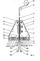
- the device shown in FIG. 1 is a vertically installed double belt press, so that its longitudinal axis is vertical.
- this double belt press 1 does not have four but six deflection drums 2, 3, 4, 5, 6, 7.
- three of these deflection drums 2, 3, 4 are arranged such that they sit at the corners of a right-angled triangle , the right angle being at the deflection drum 2.
- the press belts 8 and 9 are tensioned by means of hydraulic cylinders 10 and 11, which are fastened to the deflection drums 4 and 6, respectively.
- the deflection drums rotate in accordance with the arrows shown in FIG. 1, so that the press belts move in the direction of the arrow.
- a trough 12 is arranged below the horizontal catheter of the right-angled triangle in such a way that it extends along the press belt stretched between the deflection drums 2 and 3.
- the tub 12 is filled with an electrolyte 14, which consists of a copper sulfate solution.
- the tub 12 is filled to the extent that the outer surface of the press belt 8 is covered with the electrolyte 14.
- a plate 15 which in an appropriate distance from the part of the outer surface of the press belt which is immersed in the tub 12.
- This plate 15 has the same width as the press belt 8 and preferably a length which corresponds to the smallest distance between two peripheral points of the two deflection drums 2 and 3.
- the plate 16 is at a short distance from the press belt 8.
- a liquid metal 81 for example mercury (see also FIG. 4).
- the edges of the plate 16 are equipped with sliding seals 80 lying on the inner surface of the press belt, so that the liquid metal cannot escape from this intermediate space.
- the plates 15 and 16 are made of lead.
- the plate 15 located in the tub 12 is connected to the positive pole of a DC voltage source via a line with a sufficiently large cross section, so that it acts as an anode.
- the plate 16 attached to the inner surface of the press belt is connected to the negative pole of the same DC voltage source, so that that part of the press belt 8 which slides along the plate 16 and has electrical contact with the plate 16 via the liquid metal 81 made of mercury, than Cathode works.
- copper atoms are now deposited from the electrolyte 14 in the trough 12 on the location of the outer surface of the press belt 8 which acts as a cathode, opposite the anode 15.
- the layer thickness of the copper layer on the belt surface increases during the passage through the trough 12 and the layer thickness reaches its maximum value at the deflection drum 3 when it leaves the trough 12. This becomes direct according to the method according to the invention on the press belt galvanically deposited copper foil 17 is then transported with the press belt in the direction of the reaction zone 18 of the double belt press.
- the dimensioning of the DC voltage source which is usually represented by a mains transformer with a subsequent rectifier, is carried out according to the known laws of electrolysis.
- the temperature of the electrolyte in the tub 12 is constantly checked by means of temperature sensors mounted in the tub and kept constant by supplying appropriately tempered electrolytes.
- the used electrolyte is replaced at the same time by supplying it with fresh electrolyte, since the deposition of the copper ions on the strip surface reduces its concentration accordingly.
- both the temperature and the concentration of the electrolyte are constant over the entire deposition period.
- the plate 15, which is the anode In order to automatically keep the concentration of copper ions in the electrolyte constant, it is also possible to manufacture the plate 15, which is the anode, from copper and to use an acidic copper sulfate solution as the electrolyte liquid. During the electrolysis process, as many copper ions from the anode dissolve as copper ions from the electrolyte are reduced on the strip surface and are deposited there. The anode is of course used up and must be replaced from time to time with a new copper plate.
- the press belt 8 with the copper foil 17 electroplated on its surface moves at a uniform speed and leaves the electrolyte bath in the tub 12 at the deflection drum 3.
- the copper foil 17 is transported further to the deflection drum 4 with the press belt 8.
- the surface which is now on top can be treated for better adhesion of the copper foil 17 to the core layer.
- Such a treatment belonging to the prior art can be, for example, an etching of the copper foil surface or the deposition of strongly bud-forming brass coatings on the copper foil surface opposite the press belt.
- the copper foil 17 resting on the press belt 8 is deflected on the deflection drum 4 such that it now moves into the reaction zone 18 of the double belt press 1.
- webs 21a, 21b, 22a, 22b which consist of glass fiber fabric impregnated with epoxy resin, are also introduced into the reaction zone 18.
- These glass fiber webs form the core of the electrical laminate and are continuously drawn off from unwinding units 19a, 19b, 20a, 20b, which are located in the vicinity of the deflection drums 4 and 6.
- the core of the electrical laminate is formed by four layers of glass fiber webs. However, depending on the desired thickness and stability of the electrical laminate, more or fewer glass fiber webs can be used.
- all unwinding units can also be located at the deflection drum 4 or 6, or the unwinding units can be divided into the individual deflection drums according to the available space.
- the copper foils, glass fiber sheets as well as the electrical laminate are drawn exaggeratedly thick in relation to the double belt press for reasons of illustration.
- the second half of the press belt 25 consists of the Deflection drums 5, 6, 7 and the press belt 9, on the underside along the deflection drums 5 and 7 also a tub 13 is mounted. Analogous to the tub 12, this tub 13 contains an electrolyte liquid 14 and an anode 15. On the inside of the press belt 9 there is also a cathode 16 opposite the anode, the power supply being effected via liquid mercury, as explained further above, so that the Press belt 9 deposits a copper foil 23. This copper foil 23 is transported with the press belt 9 to the deflection drum 6 and deflected there into the reaction zone 18.
- the press belt unit 25 instead of on the press belt unit 24 as described.
- the reaction zone 18 there is the copper foil 17 on the press belt 8, on the surface facing away from the press belt 8 the impregnated glass fiber web 21a lies.
- the remaining glass fiber webs are in turn stacked on this glass fiber web 21a in the order 21b, 22b and 22a.
- the second surface of the web 22a lies against the press belt 9.
- a double-sided laminated electrical laminate is shown in FIG. 1, so that the web 22a lies against the surface of the copper foil 23.
- this copper foil 23 lies on the press belt 9 with the second surface. It should be noted in particular that if a surface treatment for improving the adhesion of the copper foil to the glass fiber core has taken place, the treated surface now rests on the respective glass fiber web 21a or 22a.
- the epoxy resin is cured by the pressure exerted on the material web in the reaction zone 18 and possibly with the additional use of heat, while the material web moves continuously through the reaction zone 18 and the glass fiber webs 21a, 21b, 22b, 22a are bonded to one another as well as to the adjacent copper foils 17, 23 connected to a solid unit, the so-called electrolaminate.
- the reaction zone can be divided into a heating zone which begins at the inlet into the double belt press at the deflection drums 4 and 6 and into a cooling zone which ends at the outlet at the deflection drums 2 and 5. This allows the material web to be cooled under pressure after the resin has hardened, which further improves the quality of the electrical laminate.
- the press belts 8 and 9 are deflected again and run into the tubs 12 and 13 of the electrolyte bath, where they are again coated with a copper foil.
- the now hardened electrolaminate separates, the surface of which consists of the copper foils 17 and 23 from the respective press belts 8 and 9. This separation generally presents no difficulties, since the copper galvanized onto the press belts made of stainless steel does not work well adheres to the surface of the press belt and in particular does not form a bond with this surface.
- the electrolaminate web 33 After the electrolaminate web 33 has left the double belt press, it is divided into individual plates according to the requirements by a cross-cutting saw which is not shown in FIG. 1. These copper-clad plates can be stacked in pallets for removal. Alternatively, if it is a flexible electrical laminate, the electrical laminate web 33 can be deflected with a deflection roller 32 and wound up into a roll in a winding unit 34.
- FIG. 2 A device for carrying out the method according to the invention, which operates in accordance with FIG. 1 and the above description, but in which the outlet and inlet are reversed, is shown in FIG. 2.
- the press belts 8 and 9 now move in the opposite direction according to the arrows .
- the copper foils 17 and 23 reach their maximum thicknesses when leaving the electrolyte bath at the deflection drums 2 and 5.
- the glass fiber webs impregnated with resin are now unwound from unwinding rollers 35a, 35b, 35c, 35d, which are located in the vicinity of the deflection drums 2 and 5, now run into the inlet of the double belt press at the deflection drums 2 and 5 and are pressed in the reaction zone 18 with the copper foils 17 and 23.
- the electrical laminate web 36 leaves the double belt press at the upper end at the deflection drums 4 and 6 and, if it is a flexible electrical laminate, is deflected with the deflection roller 37 so that it can be wound onto a roll in the winding unit 38.
- the electrical laminate web 36 can be cut behind the deflection drums 4 and 6 into panels of the desired size.
- FIG. 3 A further exemplary embodiment for carrying out the method according to the invention can be seen in FIG. 3.
- an ordinary double belt press as used for the production of decorative laminates.
- this double belt press is together with the unwind and open winding units set up rotated by 90 degrees to a longitudinal axis, so that the broad side of the press belts is now vertical, ie the double belt press is upright.
- This double belt press 40 has two adjacent press belt units 49, 50, in each of which two deflection drums 41, 42 and 43, 44 are mounted.
- An endless press belt 45, 46 is tensioned around two of these deflection drums, which in turn consists of a high-tensile stainless steel.
- the tension of the press belts 45, 46 is applied by hydraulic cylinders 47, 48, which are attached to the deflection rollers 41, 44.
- the deflection drums move in accordance with the arrows shown, so that the two press belts 45, 46 move in opposite directions.
- a trough 52 on the outer surface of the press belt 46, the height of which trough encompasses the entire broad side of the press belt.
- This tub 52 is equipped at the edges with seals 53 which slide against the press belt 46.
- the electrolyte liquid 54 which in turn consists of a copper sulfate solution.
- the tub 52 is further subjected to negative pressure, so that when the press belt 46 moves, supported by the seals 53, no electrolyte liquid emerges from the tub.
- the slide strips 56 are made of a metal and slidely touch the press belt 46.
- the support plate 55 is connected to the negative pole of the DC voltage source, so that the part of the press belt 46 located in the electrolyte 54 acts as a cathode via the slide strips 56.
- the tub 52 is made of a highly conductive metal and is connected to the positive pole of the DC voltage source, whereby the tub 52 itself is connected as an anode.
- a film 59 made of copper is deposited on the press belt strand located in the electrolyte, which is continuously moved through the trough 52, the maximum thickness of which is reached when the press belt strand has reached the 'delimitation of the trough 52 on the left in the drawing.
- the copper foil 59 lying on the press belt 46 is then deflected on the deflection drum 41 and introduced into the reaction zone 51.
- unwinding units 60 located in front of the double belt press with respect to the direction of movement of the material web, which, like the double belt press, are arranged vertically upright, webs 61 are continuously drawn off and pulled through the double belt press between the two copper foils 59, 69.
- These tracks 61 in turn consist of glass fiber fabric impregnated with epoxy resin.
- the number of unwinding units 60 depends on the desired structure of the core layer of the electrical laminate.
- the glass fiber webs are pressed together with the two copper foils under the action of heat to form an electrical laminate 62, which continuously leaves the double belt press 40 on the right-hand side in the drawing.
- FIG. 3 A further expedient embodiment of the method according to the invention is shown in FIG. 3 with the double belt unit 49 lying on the left in the forward direction.
- the galvanization of the copper foil 69 on the press belt 45 is carried out there by the tampon method known per se.
- a plate 70 which is connected to the positive pole of the direct voltage source and thus acts as an anode and is made of platinum, is covered with a sponge-like felt fabric 71.
- This felt fabric 71 has a certain width, so that the distance of the anode 70 from the press belt 45 is very precisely defined.
- the felt fabric 71 is impregnated with the electrolyte liquid consisting of copper sulfate.
- the press belt 45 is again connected as a cathode. Since a very small distance between anode 70 and press belt 45 is possible with the aid of the felt fabric, high current densities and thus high deposition rates of copper on the press belt surface 45 are obtained.
- the felt fabric 71 also serves as a kind of vessel for the electrolyte liquid. This advantageously eliminates the need for complex sealing devices which are necessary in the trough-shaped bath 52 in order to prevent the electrolyte liquid from flowing out.
- the electrolyte liquid can also be continuously moved through the felt fabric 71 with a pump.
- electrolyte liquids can also be used which are provided with certain additives in order to achieve an improved deposition of the copper. Such electrolyte liquids are known per se in the galvanizing process using the tampon process.
- the tampon method described can also be used for the double belt unit lying on the right in the forward direction in FIG. 3. If it appears desirable, the devices according to FIGS. 1 and 2 can also be provided with such a felt fabric 71 instead of the tub with the electrolyte liquid.
Landscapes
- Engineering & Computer Science (AREA)
- Chemical & Material Sciences (AREA)
- Metallurgy (AREA)
- Organic Chemistry (AREA)
- Physics & Mathematics (AREA)
- Chemical Kinetics & Catalysis (AREA)
- Electrochemistry (AREA)
- Materials Engineering (AREA)
- Mechanical Engineering (AREA)
- Fluid Mechanics (AREA)
- Manufacturing & Machinery (AREA)
- Microelectronics & Electronic Packaging (AREA)
- Laminated Bodies (AREA)
- Electroplating Methods And Accessories (AREA)
- Production Of Multi-Layered Print Wiring Board (AREA)
- Manufacturing Of Printed Wiring (AREA)
Abstract
Die Erfindung betrifft ein kontinuierliches Verfahren zur Herstellung von kupferkaschierten Laminaten (33), bei dem die benötigten Kupferfolien vor der Reaktionszone galvanisch auf den Pressbändern (89) abgeschieden werden. Anschliessend werden diese Kupferfolien von den Pressbändern in Richtung Reaktionszone transportiert, mit den harzimprägnierten Schichtstoffbahnen (21a, 21b, 22a, 22b) zusammengeführt und in der Reaktionszone mit den Schichtstoffbahnen zu einem kupferkaschierten Laminat verpresst. Die Vorrichtung zur Durchführung des Verfahrens besteht aus einer vertikal oder hochkant aufgestellten Doppelbandpresse, die auf der der Reaktionszone abgewandten Seite einen zur Aufnahme des Elektrolyten für die Kupferabscheidung geeigneten Hohlraum (12) und eine Anode (15) an der Aussenseite des Pressbandes besitzt. Im Bereich dieses Hohlraums ist das Pressband als Kathode geschaltet. Vor der in die Reaktionszone einlaufseitigen Umlenktrommel (4) sind die Abwickeleinheiten für die Schichtstoffbahnen angebracht.The invention relates to a continuous process for producing copper-clad laminates (33), in which the copper foils required are galvanically deposited on the press belts (89) before the reaction zone. These copper foils are then transported from the press belts in the direction of the reaction zone, brought together with the resin-impregnated laminate webs (21a, 21b, 22a, 22b) and pressed into a copper-clad laminate in the reaction zone with the laminate webs. The device for carrying out the method consists of a vertical or upright double belt press, which on the side facing away from the reaction zone has a cavity (12) suitable for receiving the electrolyte for copper deposition and an anode (15) on the outside of the press belt. In the area of this cavity, the press belt is connected as a cathode. The unwinding units for the laminate webs are attached in front of the deflection drum (4) on the inlet side into the reaction zone.
Description
Die Erfindung betrifft ein Verfahren zur Herstellung kupferkaschierter Laminate gemäss dem Oberbegriff des Patentanspruchs 1 und eine Vorrichtung zur Durchführung dieses Verfahrens.The invention relates to a method for producing copper-clad laminates according to the preamble of
Solche kupferkaschierten Laminate, auch Elektrolaminate genannt, dienen als Ausgangsmaterial für Leiterplatten und bestehen aus einem Kern aus mehreren Lagen von isolierendem Material, das mit einem vorkondensierten Harz getränkt ist. Üblicherweise werden für diese Lagen mit Phenolharz getränkte Hartpapiere oder mit Epoxyharz getränkte Glasfasergewebe, das sogenannte Prepreg, verwendet. Auf einer oder beiden Oberflächen des Kerns befindet sich eine elektrolytisch abgeschiedene Kupferfolie von hohem Reinheitsgrad. Das Prepreg wird zusammen mit der Kupferfolie unter Wärmeeinwirkung zu dem Elektrolaminat verpresst.Such copper-clad laminates, also called electrolaminates, serve as the starting material for printed circuit boards and consist of a core of several layers of insulating material which is impregnated with a precondensed resin. For these layers, phenolic resin-impregnated hard papers or epoxy resin-impregnated glass fiber fabrics, the so-called prepreg, are usually used. An electrolytically deposited copper foil of high purity is located on one or both surfaces of the core. The prepreg is pressed together with the copper foil under the action of heat to form the electrical laminate.
Die Ausgangsmaterialien zur Herstellung von Elektrolaminaten, d.h. die harzimprägnierten Kernlagen sowie die Kupferfolie sind bahnförmig auf Rollen verfügbar. Die Herstellung der elektrolytisch abgeschiedenen Kupferfolien erfolgt mit Hilfe einer Trommel aus Edelstahl, die mit einem Teil der Oberfläche in ein Bad taucht, das Kupferionen in Lösung enthält. Im Bad befindet sich eine der Trommel gegenüberliegende Anode. Die Trommel wird als Kathode geschaltet. Auf dem im Bad befindlichen Teil der Trommeloberfläche scheiden sich dann Kupferionen aufgrund des zwischen Anode und Kathode befindlichen elektrischen Feldes ab. Von der gleichmässig rotierenden Trommel kann die Kupferfolie kontinuierlich abgezogen und aufgewickelt werden (siehe G. Leonida, Handbook of printed circuit design, manufacture, components & assembly, erschienen in Electrochemical Publications Limited, 1981). Es sind auch Verfahren bekannt geworden, bei denen die Kupferfolie nicht auf rotierenden Trommeln sondern auf streifenförmigen Bändern abgeschieden wird (siehe DE-OS 28 39 481).The starting materials for the production of electrical laminates, ie the resin-impregnated core layers and the copper foil, are available in rolls on rolls. The electrolytically deposited copper foils are produced with the help of a stainless steel drum, which dips part of the surface into a bath that contains copper ions in solution. In the bathroom there is an anode opposite the drum. The drum is switched as a cathode. Copper ions are then deposited on the part of the drum surface in the bath due to the electrical field located between the anode and cathode. The copper foil can be continuously removed from the uniformly rotating drum and wound up (see G. Leonida, Handbook of printed circuit design, manufacture, components & assembly, published in Electrochemical Publications Limited, 1981). Methods have also become known in which the copper film is not deposited on rotating drums but on strip-shaped belts (see DE-OS 28 39 481).
Bei der kontinuierlichen Herstellung von Elektrolaminaten werden solchermassen hergestellte Kupferfolien und die Schichtstoffbahnen in Rollen von Abwickeleinheiten kontinuierlich abgewickelt, dem Aufbau des Elektrolaminats entsprechend mit gleicher Geschwindigkeit zusammengeführt und in einer Doppelbandpresse zu dem Elektrolaminat verpresst. Diesen Stand der Technik kennzeichnet die Offenlegungsschrift DE-OS 33 07 057.In the continuous production of electrolaminates, copper foils produced in this way and the laminate webs are continuously unwound in rolls of unwinding units, brought together at the same speed in accordance with the structure of the electrolaminate and pressed to the electrolaminate in a double belt press. This prior art characterizes the published patent application DE-OS 33 07 057.
Nachteilig bei diesem bekannten Verfahren ist die Zweistufigkeit. Die Kupferfolien werden wie geschildert elektrolytisch abgeschieden, anschliessend aufgerollt und zwischengelagert bis sie mit dem Schichtstoff verpresst werden. Dabei ist es unumgänglich, dass sich während der Lagerung und insbesondere auch beim Abwickeln der Kupferfolie vor der Doppelbandpresse durch elektrostatische Anziehung Staubpartikel auf der Oberfläche der Kupferfolie absetzen. Besonders die Staubpartikel die sich auf der Oberfläche der Kupferfolie befinden, die dem Schichtstoff abgewandt ist, führen zu minderwertigen Elektrolaminaten, indem sie beim Verpressen in die Oberfläche der Kupferfolie eingedrückt werden und dort zu Fehlstellen führen. Zwar werden bei dem Verfahren in genannter Offenlegungsschrift vor der Doppelbandpresse Abstreifer angeordnet, die den Staub vor Einlauf in die Doppelbandpresse entfernen sollen, jedoch hat es sich gezeigt, dass es mit dieser Massnahme nicht gelingt, sämtlichen anhaftenden Staub zu entfernen.The disadvantage of this known method is the two-stage process. The copper foils are electrolytically deposited as described, then rolled up and stored temporarily until they are pressed with the laminate. It is imperative that dust particles settle on the surface of the copper foil due to electrostatic attraction during storage and in particular also when the copper foil is being unwound in front of the double belt press. In particular, the dust particles that are on the surface of the copper foil that faces away from the laminate lead to inferior electrolaminates by being pressed into the surface of the copper foil during pressing and causing defects there. Although in the process mentioned in the publication, wipers are arranged in front of the double belt press to remove the dust before it enters the double belt press, it has been shown that this measure does not succeed in removing all the adhering dust.
Ein weiterer diesem Verfahren anhaftender Nachteil ist darin zu sehen, dass es das Verpressen von ultradünnen Kupferfolien, das sind Kupferfolien mit einer Dicke von weniger als 10 Mikrometern, nicht gestattet. Solche ultradünnen Kupferfolien sind nur sehr schwer zu handhaben, da sie extrem empfindlich und bei der kontinuierlichen Abwicklung von der Rolle stark rissgefährdet sind. Ausserdem wirken sich hier Staubablagerungen auf der Kupferfolienoberfläche noch viel gravierender aus.Another disadvantage associated with this method is that it does not allow the pressing of ultra-thin copper foils, that is to say copper foils with a thickness of less than 10 micrometers. Such ultra-thin copper foils are very difficult to handle, since they are extremely sensitive and are very susceptible to tearing when continuously unwound from the roll. In addition, dust deposits on the copper foil surface have a much more serious effect.
Andrerseits ist die Verwendung solcher ultradünner Kupferfolien an und für sich wünschenswert, da bei Weiterverarbeitung des Elektrolaminats zu Leiterplatten sowohl die Ätzzeit wie auch der Materialverbrauch wesentlich verringert wird. Bei Herstellung von Feinstleiterbahnen mit einer grosser Leiterbahndichte ist aufgrund der Unter- ätzung der Leiterbahnen keine dicke Kupferfolie verwendbar und der Einsatz von ultradünnen Folien daher unumgänglich.On the other hand, the use of such ultra-thin copper foils is desirable in and of itself, since both the etching time and the material consumption are significantly reduced when the electrical laminate is further processed into printed circuit boards. When producing ultra-fine conductor tracks with a high density of conductor tracks, thick copper foil cannot be used due to the undercut of the conductor tracks and the use of ultra-thin foils is therefore essential.
Eine weitere Schwierigkeit, die besonders bei der Verwendung von ultradünnen Kupferfolien auftritt, besteht darin, dass eine Bildung von Falten durch unterbundene Wärmedehnung der Folie bei der Verpressung nur schwer zu verhindern ist. Ebenso ist das Vorhandensein feinster Poren in der Kupferfolie kaum zu vermeiden. Diese Mikroporen gestatten ein Durchfliessen des geschmolzenen Epoxyharzes beim Verpressen auf die Pressbandoberfläche. Das ausfliessende Harz breitet sich dann in der Fuge zwischen Folie und Pressband aus und deckt die Kupferfolie beim fertigen Elektrolaminat gegen die Einwirkung von Ätzmitteln ab, was somit noch wesentlich grössere Fehlstellen als die Pore allein verursacht.Another difficulty, which arises especially when using ultra-thin copper foils, is that it is difficult to prevent wrinkles from forming due to the thermal expansion of the foil being prevented during compression. Likewise, the presence of the finest pores in the copper foil can hardly be avoided. These micropores allow the melted epoxy resin to flow through when pressed onto the surface of the press belt. The outflowing resin then spreads out in the joint between the foil and the press belt and covers the copper foil in the finished electrical laminate against the action of etching agents, which therefore causes even larger defects than the pore alone.
Zumindestens beim Verpressen von Schichtstoffen mit ultradünner Kupferfolie in diskontinuierlichen Ein- oder Mehretagenpressen zu einer Elektrolaminattafel ist es bekannt, diese ultradünnen Folien bei der elektrolytischen Herstellung auf einem Träger, der beispielsweise aus einer Aluminiumbahn besteht, abzuscheiden (siehe DE-AS 24 13 669). Die ultradünne Kupferfolie wird anschliessend zusammen mit dem Träger und den Schichtstoffen verpresst. Nach dem Verpressen wird der Träger von der Kupferfolienoberfläche wieder abgezogen. Nachteilig ist bei diesem Verfahren, dass zusätzlich ein teurer Träger gebraucht wird, der nach dem Verpressen als Abfall nicht weiter verwendet werden kann.At least when pressing laminates with ultra-thin copper foil in discontinuous single or multi-day presses to form an electrolaminate board, it is known to deposit these ultra-thin foils during electrolytic production on a carrier that consists, for example, of an aluminum sheet (see DE-AS 24 13 669). The ultra-thin copper foil is then pressed together with the carrier and the laminates. After pressing, the carrier is pulled off the copper foil surface again. The disadvantage of this method is that an expensive carrier is also required, which can no longer be used as waste after pressing.
Der vorliegenden Erfindung liegt die Aufgabe zugrunde, ein kontinuierliches mit Flächenpressung arbeitendes Verfahren anzugeben, das eine Zwischenlagerung der empfindlichen Kupferfolie vermeidet, die Gefahr von Fehlstellen durch Staub, Falten- oder Porenbildung auf der Kupferfolie sehr stark verringert und auch eine Verwendung von ultradünnen Kupferfolien ohne den sonst üblichen, teuren Träger gestattet.The present invention has for its object to provide a continuous process with surface pressure that avoids intermediate storage of the sensitive copper foil, the risk of defects due to dust, wrinkles or pore formation on the copper foil very much reduced and also the use of ultra-thin copper foils without the otherwise usual, expensive carrier allowed.
Die Lösung dieser Aufgabe wird durch die im Kennzeichen des Patentanspruchs 1 beschriebenen technischen Lehre vermittelt und zur Durchführung dieses Verfahrens dienende Vorrichtungen werden im Kennzeichen der Patentansprüche 7 bis 9 angegeben.The solution to this problem is conveyed by the technical teaching described in the characterizing part of
Die mit der Erfindung erzielbaren Vorteile bestehen insbesondere darin, dass das kontinuierliche Verfahren nicht mehr zweistufig, sondern einstufig abläuft. Damit erübrigt sich eine Zwischenlagerung und zusätzliche Handhabung der Kupferfolie und die dadurch bedingten Beschädigungsgefahren der Kupferfolie entfallen. Da die am fertigen Elektrolaminat aussenliegende Oberfläche der Kupferfolie bis nach der Verpressung ständig vom Pressband bedeckt ist, können sich auf dieser Oberfläche keine Staubpartikel absetzen, womit die Gefahr von Fehlstellen im Elektrolaminat gebannt ist. Durch die direkte Abscheidung der Kupferfolie auf dem Pressband erhält diese schon bei der Abscheidung die Temperatur des Pressbandes, womit Faltenbildungen vermieden werden. Bei der vorteilhaften Verwendung der Tampon-Galvanisiermethode ist durch die ständige Reibbeanspruchung der sich abscheidenden Folienoberfläche die Gefahr von Mikroporen in der Kupferfolie völlig eliminiert. Die dünne Kupferfolie wird vor der Verpressung ständig vom Pressband getragen, womit die Notwendigkeit eines zusätzlichen Trägers für eine ultradünne Kupferfolie völlig entfällt. Das erfindungsgemässe Verfahren steigert die Qualität des Erzeugnisses und verringert entscheidend dessen Kosten.The advantages that can be achieved with the invention consist in particular in the fact that the continuous process no longer proceeds in two stages, but in one stage. This eliminates the need for intermediate storage and additional handling of the copper foil and the associated risk of damage to the copper foil. Since the surface of the copper foil on the finished electrical laminate is continuously covered by the press belt until after pressing, no dust particles can settle on this surface, thus eliminating the risk of defects in the electrical laminate. Due to the direct deposition of the copper foil on the press belt, it receives the temperature of the press belt during the deposition, thereby avoiding wrinkles. With the advantageous use of the tampon electroplating method, the risk of micropores in the copper foil is completely eliminated due to the constant stress on the surface of the deposited foil. The thin copper foil is constantly carried by the press belt before pressing, which completely eliminates the need for an additional support for an ultra-thin copper foil. The method according to the invention increases the quality of the product and significantly reduces its cost.
Eine bevorzugte Ausführungsform zur Durchführung des erfindungsgemässen Verfahrens ist in den Zeichnungen dargestellt und wird im folgenden näher beschrieben. Es zeigen
- Fig. 1 eine Vorrichtung zur Abscheidung der Kupferfolie und Verpressung zum Elektrolaminat,
- Fig. 2 eine Vorrichtung entsprechend Fig. 1 mit vertauschten Ein- und Auslauf der Doppelbandpresse,
- Fig. 3 eine Vorrichtung zur Durchführung des Verfahrens, die aus einer hochkant gestellten Doppelbandpresse besteht und
- Fig. 4 einen vergrösserten Teilausschnitt aus Fig. 1 zur Übertragung der Spannung auf das Pressband mittels Quecksilber.
- Fig. 1 shows a device for the deposition of copper foil and pressing to the electrical laminate,
- 2 shows a device corresponding to FIG. 1 with the inlet and outlet of the double belt press reversed,
- Fig. 3 shows an apparatus for performing the method, which consists of an upright double belt press and
- FIG. 4 shows an enlarged partial section from FIG. 1 for transferring the tension to the press belt by means of mercury.
Bei der in Fig. 1 gezeigten Vorrichtung handelt es sich um eine vertikal aufgestellte Doppelbandpresse, so dass deren Längsachse vertikal steht. Diese Doppelbandpresse 1 besitzt jedoch im Gegensatz zu einer herkömmlichen Doppelbandpresse nicht vier sondern sechs Umlenktrommeln 2, 3, 4, 5, 6, 7. Jeweils drei dieser Umlenktrommeln 2, 3, 4 sind so angeordnet, dass sie an den Ecken eines rechtwinkligen Dreiecks sitzen, wobei der rechte Winkel sich bei der Umlenktrommel 2 befindet. Über diese drei Umlenktrommeln ist ein Pressband 8 gespannt, das aus einem hochzugfesten Edelstahl besteht. Diese Anordnung wiederholt sich spiegelbildlich zu einer Linie A-A entlang der vertikalen Kathete des Dreiecks, wobei diese Anordnung aus den Umlenktrommeln 5, 6, 7 und dem Pressband 9 besteht. Die Pressbänder 8 und 9 werden mittels Hydraulikzylinder 10 und 11, die an den Umlenktrommeln 4 bzw. 6 befestigt sind, gespannt.The device shown in FIG. 1 is a vertically installed double belt press, so that its longitudinal axis is vertical. In contrast to a conventional double belt press, however, this
Die Umlenktrommeln drehen sich entsprechend der in Fig. 1 eingezeichneten Pfeile, so dass die Pressbänder sich entsprechend der Pfeilrichtung bewegen. Unterhalb der horizontalen Kathete des rechtwinkligen Dreiecks ist eine Wanne 12 so angeordnet, dass sie sich entlang des zwischen den Umlenktrommeln 2 und 3 gespannten Pressbandes erstreckt. Die Wanne 12 ist mit einem Elektrolyten 14 gefüllt, der aus einer Kupfersulfatlösung besteht. Die Wanne 12 ist dabei soweit gefüllt, dass die aüssere Oberfläche des Pressbandes 8 mit dem Elektrolyten 14 bedeckt wird. In dieser Wanne befindet sich eine Platte 15, die in einem zweckmässigen Abstand dem Teil der Aussenfläche des Pressbandes, das in die Wanne 12 eintaucht, gegenüberliegt. Diese Platte 15 besitzt dieselbe Breite wie das Pressband 8 und vorzugsweise eine Länge, die dem kleinsten Abstand zweier Peripheriepunkte der beiden Umlenktrommeln 2 und 3 entspricht. Auf der inneren Oberfläche des Pressbandes 8, der Platte 15 gegenüberliegend, liegt eine weitere Platte 16, die dieselbe Grösse wie die Platte 15 besitzt. Die Platte 16 besitzt zum Pressband 8 einen geringen Abstand. In diesem Raum zwischen der Platte 16 und der Innenfläche des Pressbandes 8 befindet sich ein flüssiges Metall 81, beispielsweise Quecksilber (siehe auch Fig. 4). Die Ränder der Platte 16 sind mit an der Pressbandinnenfläche anliegenden Gleitdichtungen 80 ausgestattet, so dass das flüssige Metall nicht aus diesem Zwischenraum austreten kann.The deflection drums rotate in accordance with the arrows shown in FIG. 1, so that the press belts move in the direction of the arrow. A
Die Platten 15 und 16 bestehen aus Blei. Die in der Wanne 12 befindliche Platte 15 ist über eine Leitung mit genügend grossem Querschnitt mit dem positiven Pol einer Gleichspannungsquelle verbunden, so dass sie als Anode wirkt. Die auf der Innenfläche des Pressbandes angebrachte Platte 16 ist mit dem negativen Pol derselben Gleichspannungsquelle verbunden, so dass derjenige Teil des Pressbandes 8, der an der Platte 16 enttanggleitet und über das aus Quecksilber bestehende flüssige Metall 81 mit der Platte 16 elektrischen Kontakt besitzt, als Kathode wirkt. Gemäss dem bekannten galvanischen Prinzip scheiden sich aus dem Elektrolyten 14 in der Wanne 12 nun Kupferatome auf der der Anode 15 gegenüberliegenden Stelle der Aussenfläche des als Kathode wirkenden Pressbandes 8 ab. Da das Pressband 8 sich kontinuierlich in Pfeilrichtung vorwärtsbewegt, nimmt die Schichtdicke der Kupferschicht auf der Bandoberfläche während des Durchlaufs durch die Wanne 12 zu und die Schichtdicke erreicht ihren maximalen Wert an der Umlenktrommel 3 beim Verlassen der Wanne 12. Entsprechend dem erfindungsgemässen Verfahren wird die direkt auf dem Pressband galvanisch abgeschiedene Kupferfolie 17 dann mit dem Pressband in Richtung Reaktionszone 18 der Doppelbandpresse transportiert.The
Die Dimensionierung der Gleichspannungsquelle, die üblicherweise durch einen Netztransformator mit anschliessendem Gleichrichter dargestellt wird, erfolgt nach den bekannten Gesetzen der Elektrolyse. Um eine gleichmässige Kupferschicht abzuscheiden, wird die Temperatur des Elektrolyten in der Wanne 12 mittels in der Wanne angebrachter Temperaturfühler ständig kontrolliert und durch Zufuhr von entsprechend temperiertem Elektrolyten konstant gehalten. Durch Zufuhr mit frischem Elektrolyten wird gleichzeitig der verbrauchte Elektrolyt ersetzt, da durch die die Abscheidung der Kupferionen auf der Bandoberfläche dessen Konzentration entsprechend abnimmt. Somit ist sowohl die Temperatur wie auch die Konzentration des Elektrolyten über den gesamten Abscheidungszeitraum konstant. Da durch die plattenförmige Ausbildung von Anode und Kathode die Stromdichte im Elektrolysebad ebenfalls weitgehend konstant ist, gelingt insgesamt die Abscheidung einer gleichmässig dicken, homogenen Kupferfolie auf der Oberfläche des Bandes 8, die den hohen qualitativen Anforderungen, die an Elektrolaminate gestellt werden, genügt.The dimensioning of the DC voltage source, which is usually represented by a mains transformer with a subsequent rectifier, is carried out according to the known laws of electrolysis. In order to deposit a uniform copper layer, the temperature of the electrolyte in the
Um die Konzentration der Kupferionen im Elektrolyten automatisch konstant zu halten, besteht auch die Möglichkeit, die Platte 15, die die Anode darstellt, aus Kupfer zu fertigen und als Elektrolytflüssigkeit eine saure Kupfersulfatlösung zu verwenden. Während des Elektrolysevorganges gehen dann soviele Kupferionen von der Anode in Lösung, wie Kupferionen aus dem Elektrolyten an der Bandoberfläche reduziert werden und sich dort abscheiden. Dabei wird selbstverständlich die Anode verbraucht und ist von Zeit zu Zeit durch eine neue Kupferplatte zu ersetzen.In order to automatically keep the concentration of copper ions in the electrolyte constant, it is also possible to manufacture the
Um die Verlustleistungen so gering wie möglich zu machen, müssen die Zuleitungen des Stromes zur Anode und Kathode mit geringstmöglichem Widerstand erfolgen. Es werden daher wie in der Galvanik üblich Leitungen aus einem Material mit kleinem elektrischen Widerstand, beispielsweise Kupfer mit entsprechend grossem Querschnitt, verwendet. Diese Leitungen sind in Fig. 1 aus Übersichtlichkeitsgründen nicht eingezeichnet.In order to make the power losses as low as possible, the supply lines of the current to the anode and cathode must be made with the lowest possible resistance. Therefore, as is usual in electroplating, lines made of a material with a small electrical resistance, for example copper with a correspondingly large cross section, are used. These lines are not shown in FIG. 1 for reasons of clarity.
Das Pressband 8 mit der auf seiner Oberfläche aufgalvanisierten Kupferfolie 17 bewegt sich mit gleichförmiger Geschwindigkeit und verlässt bei der Umlenktrommel 3 das in der Wanne 12 befindliche Elektrolytbad. Mit dem Pressband 8 wird die Kupferfolie 17 zu der Umlenktrommel 4 weitertransportiert. Auf dieser Strecke zwischen den zwei Umlenktrommein 3 und 4 kann eine Behandlung der nun obenliegenden Oberfläche zur besseren Haftung der Kupferfolie 17 auf der Kernschicht erfolgen. Eine solche zum Stande der Technik gehörende Behandlung kann beispielsweise eine Anätzung der Kupferfolienoberfläche sein oder die Abscheidung von stark knospenbildenden Messingauflagen auf der dem Pressband gegenüberliegenden Kupferfolienoberfläche.The
An der Umlenktrommel 4 wird die auf dem Pressband 8 aufliegende Kupferfolie 17 so umgelenkt, dass sie sich nun in die Reaktionszone 18 der Doppelbandpresse 1 bewegt. Zusammen mit der Kupferfolie werden Bahnen 21a, 21b, 22a, 22b, die aus mit Epoxyharz imprägniertem Glasfasergewebe bestehen, in die Reaktionszone 18 mit eingeführt. Diese Glasfaserbahnen bilden den Kern des Elektrolaminats und werden von Abwickeleinheiten 19a, 19b, 20a, 20b, die sich in der Nähe der Umlenktrommeln 4 und 6 befinden, kontinuierlich abgezogen. In diesem Ausführungsbeispiel wird der Kern des Elektrolaminats von vier Lagen von Glasfaserbahnen gebildet. Es können jedoch je nach gewünschter Dicke und Stabilität des Elektrolaminats mehr oder auch weniger Glasfaserbahnen verwendet werden. Falls es zweckmässig erscheint, können sich auch sämtliche Abwickeleinheiten bei der Umlenktrommel 4 oder 6 befinden bzw. die Aufteilung der Abwickeleinheiten zu den einzelnen Umlenktrommeln kann nach dem vorhandenen Platz erfolgen. Sowohl die Kupferfolien, Glasfaserbahnen als auch das Elektrolaminat sind aus Darstellungsgründen im Verhältnis zur Doppelbandpresse übertrieben dick eingezeichnet.The
Soll das Elektrolaminat beidseitig mit Kupferfolie kaschiert werden, so wird bei der zweiten Pressbandhälfte 25, bestehend aus den Umlenktrommeln 5, 6, 7 und dem Pressband 9, an der Unterseite entlang den Umlenktrommeln 5 und 7 ebenfalls eine Wanne 13 montiert. Diese Wanne 13 enthält analog zu der Wanne 12 eine Elektrolytflüssigkeit 14 und eine Anode 15. Auf der Innenseite des Pressbandes 9 befindet sich gegenüber der Anode ebenfalls eine Kathode 16, wobei die Stromzufuhr wie weiter oben erläutert über flüssiges Quecksilber erfolgt, so dass sich auf dem Pressband 9 eine Kupferfolie 23 abscheidet. Diese Kupferfolie 23 wird mit dem Pressband 9 zur Umlenktrommel 6 transportiert und dort in die Reaktionszone 18 umgelenkt. Selbstverständlich kann bei einer einseitigen Kaschierung des Elektrolaminats mit einer Kupferfolie dieselbe auch anstatt auf der Pressbandeinheit 24 auf der Pressbandeinheit 25 wie beschrieben abgeschieden werden.If the electrical laminate is to be laminated on both sides with copper foil, the second half of the
In der Reaktionszone 18 befindet sich auf dem Pressband 8 die Kupferfolie 17, an deren dem Pressband 8 abgewandten Oberfläche liegt die imprägnierte Glasfaserbahn 21a an. An diese Glasfaserbahn 21a sind wiederum die übrigen Glasfaserbahnen in der Reihenfolge 21b, 22b und 22a geschichtet. Falls es sich um ein einseitig kaschiertes Elektrolaminat handelt, liegt die zweite Oberfläche der Bahn 22a an dem Pressband 9 an. In Fig. 1 ist ein zweiseitig kaschiertes Elektrolaminat gezeigt, so dass die Bahn 22a an der Oberfläche der Kupferfolie 23 anliegt. Mit der zweiten Oberfläche liegt diese Kupferfolie 23, wie bereits beschrieben, auf dem Pressband 9 auf. Zu bemerken ist besonders, dass falls eine Oberflächenbehandlung zur Haftverbesserung der Kupferfolie auf dem Glasfaserkern stattgefunden hat, die behandelte Oberfläche nun auf der jeweiligen Glasfaserbahn 21a bzw. 22a aufliegt.In the
Auf diese entsprechend der Beschreibung geschichtete Werkstoffbahn wird in der Reaktionszone 18 Druck ausgeübt. Dieser Druck wird über Druckplatten 26, 27 hydraulisch oder mechanisch auf die Innenseiten der Pressbänder 8, 9, d.h. die Seiten der Pressbänder die der Kupferfolie 17, 23 abgewandt sind, aufgebracht und von dort auf die Werkstoffbahn übertragen. Bei der hydraulischen Druckübertragung wird in dem Raum 28, der zu den Seiten von der Druckplatte 26 und der Innenseite des Pressbandes 8 und nach oben und unten von der Dichtung 29 begrenzt wird, ein unter Druck setzbares, fluides Druckmedium, beispielsweise Öl oder Luft, eingebracht. Zur mechanischen Druckübertragung sind zwischen der Druckplatte 27 und der Innenseite des Pressbandes 9 ortsfeste Rollen 30 angebracht. Mit Hilfe von Hydraulikzylindern 31 werden die Druckplatte 27 und damit die Rollen 30 gegen die Innenseite des Pressbandes 9 angestellt. Das Pressengestell, das die von der Werkstoffbahn ausgehenden Reaktionskräfte aufnimmt und in dem sowohl die Druckplatten 26, 27 als auch beide Pressbandeinheiten 24, 25 gelagert sind, ist in der Zeichnung der Übersichtlichkeit halber weggelassen.Pressure is exerted on this material web layered according to the description in the
Durch den auf die Werkstoffbahn in der Reaktionszone 18 ausgeübten Druck und gegebenenfalls unter zusätzlichem Einsatz von Wärme wird das Epoxyharz ausgehärtet, während sich die Werkstoffbahn kontinuierlich durch die Reaktionszone 18 hindurchbewegt und die Glasfaserbahnen 21a, 21b, 22b, 22a werden sowohl untereinander als auch mit den anliegenden Kupferfolien 17, 23 zu einer festen Einheit, dem sogenannten Elektrolaminat, verbunden. Falls es erforderlich ist, kann die Reaktionszone in eine am Einlauf in die Doppelbandpresse bei den Umlenktrommeln 4 und 6 beginnende Heizzone und in eine Kühlzone eingeteilt sein, die am Auslauf bei den Umlenktrommeln 2 und 5 endet. Damit kann die Werkstoffbahn nach Aushärten des Harzes unter Druck gekühlt werden, was die Qualität des Elektrolaminats weiter verbessert.The epoxy resin is cured by the pressure exerted on the material web in the
Am Auslauf aus der Doppelbandpresse, bei den Umlenktromrnein 2 und 5, werden die Pressbänder 8 und 9 wieder umgelenkt und laufen in die Wannen 12 und 13 des Elektrolytbades ein, wo sie erneut mit einer Kupferfolie beschichtet werden. Dabei trennt sich das nun ausgehärtete Elektrolaminat, dessen Oberfläche aus den Kupferfolien 17 und 23 besteht von den jeweiligen Pressbändern 8 und 9. Diese Trennung bereitet in der Regel keine Schwierigkeiten, da das auf die aus Edelstahl bestehenden Pressbänder aufgalvanisierte Kupfer schlecht auf der Pressbandoberfläche haftet und insbesondere keinen Verbund mit dieser Oberfläche eingeht.At the outlet from the double belt press, at the
Nachdem die Elektrolaminatbahn 33 die Doppelbandpresse verlassen hat, wird sie durch eine mitlaufende Quersäge, die in Fig. 1 nicht eingezeichnet ist, in einzelne Platten entsprechend den Anforderungen aufgeteilt. Diese kupferkaschierten Platten können in Paletten zum Abtransport gestapelt werden. Alternativ kann, falls es sich um ein flexibles Elektrolaminat handelt, die Elektrolaminatbahn 33 mit einer Umlenkrolle 32 umgelenkt und in einer Aufwickeleinheit 34 zu einer Rolle aufgewickelt werden.After the
Eine Vorrichtung zur Durchführung des erfindungsgemässen Verfahrens, die entsprechend der Fig. 1 und der obigen Beschreibung arbeitet, bei der jedoch Aus- und Einlauf vertauscht sind, zeigt die Fig. 2. Die Pressbänder 8 und 9 bewegen sich nun in entgegengesetzter Richtung entsprechend den Pfeilen. Die Kupferfolien 17 und 23 erreichen ihre maximalen Dicken bei Verlassen des Elektrolytbades bei den Umlenktrommeln 2 und 5. Die mit Harz imprägnierten Glasfaserbahnen werden nun von Abwickelrollen 35a, 35b, 35c, 35d, die sich in der Nähe der Umlenktrommeln 2 und 5 befinden abgewickelt, laufen nun in den Einlauf der Doppelbandpresse bei den Umlenktrommeln 2 und 5 ein und werden in der Reaktionszone 18 mit den Kupferfolien 17 und 23 verpresst. Die Elektrolaminatbahn 36 verlässt am oberen Ende bei den Umlenktrommeln 4 und 6 die Doppelbandpresse und wird, falls es sich um ein flexibles Elektrolaminat handelt, mit der Umlenkrolle 37 so umgelenkt, dass es in der Aufwickeleinheit 38 auf eine Rolle aufgewickelt werden kann. Alternativ kann die Elektrolaminatbahn 36 hinter den Umlenktrommeln 4 und 6 gleich in Platten der gewünschten Grösse geschnitten werden.A device for carrying out the method according to the invention, which operates in accordance with FIG. 1 and the above description, but in which the outlet and inlet are reversed, is shown in FIG. 2. The
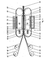
Eine weiteres Ausführungsbeispiel zur Durchführung des erfindungsgemässen Verfahrens ist in Fig. 3 zu sehen. Dort wird, im Schnitt entlang einer horizontalen Ebene, eine gewöhnliche Doppelbandpresse gezeigt, wie sie zur Herstellung dekorativer Laminate verwendet wird. Diese Doppelbandpresse ist jedoch zusammen mit den Abwickel- und Aufwickeleinheiten um 90 Grad zu einer Längsachse gedreht aufgestellt, so dass die Breitseite der Pressbänder nun vertikal steht, d.h. die Doppelbandpresse steht hochkant.A further exemplary embodiment for carrying out the method according to the invention can be seen in FIG. 3. There, on average along a horizontal plane, is shown an ordinary double belt press as used for the production of decorative laminates. However, this double belt press is together with the unwind and open winding units set up rotated by 90 degrees to a longitudinal axis, so that the broad side of the press belts is now vertical, ie the double belt press is upright.
Diese Doppelbandpresse 40 besitzt zwei nebeneinanderliegende Pressbandeinheiten 49, 50, in denen je zwei Umlenktrommein 41, 42 bzw. 43, 44 gelagert sind. Um jeweils zwei dieser Umlenktrommeln ist ein endloses Pressband 45, 46 gespannt, das wiederum aus einem hochzugfesten Edelstahl besteht. Die Spannung der Pressbänder 45, 46 wird durch Hydraulikzylinder 47, 48, die an den Umlenktromrnein 41, 44 befestigt sind, aufgebracht. Die Umlenktrommeln bewegen sich entsprechen den eingezeichneten Pfeilen, so dass die beiden Pressbänder 45, 46 sich gegensinnig bewegen.This
Zwischen den zwei Pressbändern 45, 46 wird die in der Zeichnung von links nach rechts vorlaufende Werkstoffbahn unter gleichzeitiger Anwendung von Druck und Wärme verpresst. In dieser Reaktionszone 51 wird der ausgeübte Druck über Druckplatten 57 hydraulisch oder mechanisch auf die Innenseiten der Pressbänder 45, 46 aufgebracht und von dort auf die Werkstoffbahn übertragen. In Fig. 3 ist nur die hydraulische Druckübertragung gezeigt, bei der in den Raum zwischen der Druckplatte 57 und der Pressbandinnenseite, der zu den Seiten durch Dichtungen 58 begrenzt ist, ein unter Druck setzbares Fluid eingebracht wird.Between the two
An der der Reaktionszone 51 abgewandten Seite der Pressbandeinheit 50 befindet sich an der Aussenfläche des Pressbandes 46 eine Wanne 52, deren Höhe die gesamte Breitseite des Pressbandes umfasst. Diese Wanne 52 ist an den Rändern mit Dichtungen 53 ausgestattet, die am Pressband 46 gleitend anliegen. In der Wanne 52 befindet sich die Elektrolytflüssigkeit 54, die wiederum aus einer Kupfersulfatlösung besteht. Die Wanne 52 wird weiter mit Unterdruck beaufschlagt, so dass bei Bewegung des Pressbandes 46 unterstützt durch die Dichtungen 53 keine Elektrolytflüssigkeit aus der Wanne austritt. Auf der Innenseite des Pressbandes 46, der Wanne 52 gegenüberliegend ist eine Stützplatte 55 im Pressengestell mit vorzugsweise derselben Grösse wie die Wanne 52 angebracht. In dieser Stützplatte 55 und mit ihr leitend verbunden befinden sich nebeneinanderliegende Gleitleisten 56, deren Länge so gross wie die Breitseite des Pressbandes ist. Die Gleitleisten 56 bestehen aus einem Metall und berühren das Pressband 46 gleitend.On the side of the
Die Stützplatte 55 wird mit dem negativen Pol der Gleichspannungsquelle verbunden, so dass über die Gleitleisten 56 der in dem Elektrolyten 54 befindliche Teil des Pressbandes 46 als Kathode wirkt. Die Wanne 52 ist aus einem gut leitfähigen Metall hergestellt und wird mit dem Pluspol der Gleichspannungsquelle verbunden, womit die Wanne 52 selbst als Anode geschaltet ist. Damit scheidet sich auf dem im Elektrolyten befindlichen Pressbandtrum, das kontinuierlich durch die Wanne 52 bewegt wird, eine aus Kupfer bestehende Folie 59 ab, deren maximale Dicke erreicht ist, wenn das Pressbandtrum die 'in der Zeichnung links liegende Begrenzung der Wanne 52 erreicht hat. Die an dem Pressband 46 anliegende Kupferfolie 59 wird anschliessend an der Umlenktrommel 41 umgelenkt und in die Reaktionszone 51 eingeführt.The
Von mehreren, bezüglich der Bewegungsrichtung der Werkstoffbahn vor der Doppelbandpresse befindlichen Abwickeleinheiten 60, die ebenso wie die Doppelbandpresse vertikal aufrecht angeordnet sind, werden Bahnen 61 kontinuierlich abgezogen und zwischen den beiden Kupferfolien 59, 69 durch die Doppelbandpresse hindurchgezogen. Diese Bahnen 61 bestehen wiederum aus mit Epoxyharz imprägniertem Glasfasergewebe. Die Anzahl der Abwickeleinheiten 60 richtet sich nach dem gewünschten Aufbau der Kernschicht des Elektrolaminats. In der Reaktionszone 51 werden die Glasfaserbahnen miteinander und den beiden Kupferfolien unter Einwirkung von Wärme zu einem Elektrolaminat 62 verpresst, das in der Zeichnung auf der rechten Seite die Doppelbandpresse 40 kontinuierlich verlässt.From a plurality of unwinding
Eine weitere zweckmässige Ausgestaltung des erfindungsgemässen Verfahrens ist in Fig. 3 bei der in Vorlaufrichtung links liegenden Doppelbandeinheit 49 gezeigt. Die Galvanisierung der Kupferfolie 69 auf das Pressband 45 erfolgt dort durch das an sich bekannte TamponVerfahren. Eine mit dem positiven Pol der Gleichspannungsquelle verbundene und damit als Anode wirkende Platte 70, die aus Platin besteht, ist mit einem schwammartigen Filzgewebe 71 umhüllt. Dieses Filzgewebe 71 besitzt eine bestimmte Breite, so dass der Abstand der Anode 70 von dem Pressband 45 sehr exakt definiert ist. Das Filzgewebe 71 ist mit der aus Kupfersulfat bestehenden Elektrolytflüssigkeit getränkt. Das Pressband 45 ist wie bereits weiter oben beschrieben wieder als Kathode geschaltet. Da mit Hilfe des Filzgewebes ein sehr kleiner Abstand zwischen Anode 70 und Pressband 45 möglich ist, erhält man hohe Stromdichten und damit hohe Abscheideraten von Kupfer auf der Pressbandoberfläche 45.A further expedient embodiment of the method according to the invention is shown in FIG. 3 with the
Das Filzgewebe 71 dient gleichzeitig als eine Art Gefäss für die Elektrolytflüssigkeit. Damit entfallen vorteilhafterweise aufwendige Abdichtvorrichtungen, die bei dem wannenförmigen Bad 52 nötig sind, um ein Ausfliessen der Elektrolytflüssigkeit zu verhindern. Um Temperatur- und Konzentrationskonstanz der Elektrolytflüssigkeit zu sichern, kann die Elektrolytflüssigkeit auch mit einer Pumpe durch das Filzgewebe 71 ständig durchbewegt werden. Selbstverständlich können auch Elektrolytflüssigkeiten verwendet werden, die mit bestimmten Zusätzen versehen sind, um eine verbesserte Abscheidung des Kupfers zu erreichen. Solche Elektrolytflüssigkeiten sind bei der Galvanisierung mittels des Tamponverfahrens an sich bekannt.The felt
Das beschriebene Tamponverfahren kann ebenfalls für die in Fig. 3 in Vorlaufrichtung rechts liegende Doppelbandeinheit verwendet werden. Falls es wünschenswert erscheint, können auch die Vorrichtungen entsprechend den Fig. 1 und 2 anstelle der Wanne mit der Elektrolytflüssigkeit ein solches Filzgewebe 71 erhalten.The tampon method described can also be used for the double belt unit lying on the right in the forward direction in FIG. 3. If it appears desirable, the devices according to FIGS. 1 and 2 can also be provided with such a
Claims (23)
dadurch gekennzeichnet,
dass eine Kupferschicht auf einem in Vorlaufrichtung der sich kontinuierlich bewegenden Pressbänder vor der Reaktionszone befindlichen, dem Schichtstoff zugekehrten Teil eines oder beider Pressbänder galvanisch abgeschieden, von den Pressbändern in die Reaktionszone transportiert und in der Reaktionszone mit den Schichtstoffbahnen verpresst wird.1. A process for the production of copper-clad laminates, in which the resin-impregnated laminate webs are brought together with one or two copper foils and then guided between two endless press belts moving at the same speed so that the copper foil is attached to both the top and bottom of the laminate core is in contact with the press belts and this layer structure is cured under the action of heat and pressure in the reaction zone between the two press belts,
characterized,
that a copper layer is electrodeposited on a part of one or both press belts facing the laminate in the forward direction of the continuously moving press belts in front of the reaction zone, transported by the press belts into the reaction zone and pressed with the laminate webs in the reaction zone.
Applications Claiming Priority (2)
| Application Number | Priority Date | Filing Date | Title |
|---|---|---|---|
| DE19853515629 DE3515629A1 (en) | 1985-05-02 | 1985-05-02 | METHOD AND DEVICE FOR PRODUCING COPPER-COATED LAMINATES |
| DE3515629 | 1985-05-02 |
Publications (2)
| Publication Number | Publication Date |
|---|---|
| EP0203368A1 true EP0203368A1 (en) | 1986-12-03 |
| EP0203368B1 EP0203368B1 (en) | 1989-03-08 |
Family
ID=6269529
Family Applications (1)
| Application Number | Title | Priority Date | Filing Date |
|---|---|---|---|
| EP86105597A Expired EP0203368B1 (en) | 1985-05-02 | 1986-04-23 | Method and apparatus for making copper-clad laminates |
Country Status (6)
| Country | Link |
|---|---|
| US (1) | US4687528A (en) |
| EP (1) | EP0203368B1 (en) |
| JP (1) | JPS61255858A (en) |
| CN (1) | CN1019369B (en) |
| DE (2) | DE3515629A1 (en) |
| SU (2) | SU1438636A3 (en) |
Cited By (4)
| Publication number | Priority date | Publication date | Assignee | Title |
|---|---|---|---|---|
| WO1988006647A1 (en) * | 1987-03-02 | 1988-09-07 | M & T Laminates Limited | Production of copper-clad dielectric material |
| DE3811467A1 (en) * | 1988-04-06 | 1989-10-19 | Siempelkamp Gmbh & Co | METHOD AND SYSTEM FOR THE CONTINUOUS PRODUCTION OF RAIL-BASED BASE MATERIAL FOR CIRCUIT BOARDS |
| EP0363794A2 (en) * | 1988-10-14 | 1990-04-18 | Kurt Held | Method and apparatus for the continuous production of laminates |
| US5662761A (en) * | 1992-07-21 | 1997-09-02 | Amp-Akzo Lin Lam Vof | Method of manufacturing a UD-reinforced PWB laminate |
Families Citing this family (29)
| Publication number | Priority date | Publication date | Assignee | Title |
|---|---|---|---|---|
| JPS63136695A (en) * | 1986-11-28 | 1988-06-08 | 三菱電機株式会社 | Method and apparatus for manufacturing shielding plate |
| JPS63285998A (en) * | 1987-05-18 | 1988-11-22 | Mitsubishi Electric Corp | Method and device for manufacturing multi-layer substrate |
| JPS63285997A (en) * | 1987-05-18 | 1988-11-22 | Mitsubishi Electric Corp | Method and device for manufacturing multi-layer substrate |
| US5149394A (en) * | 1988-10-14 | 1992-09-22 | Kurt Held | Method and apparatus for continuously fabricating laminates |
| US5034087A (en) * | 1989-11-16 | 1991-07-23 | Doboy Packaging Machinery, Inc. | Self-adjusting heat seal bar |
| DE4118249C2 (en) * | 1991-06-04 | 1994-10-27 | Guenther Dr Schwarz | Method and device for the mass preservation of archives |
| US5806177A (en) * | 1995-10-31 | 1998-09-15 | Sumitomo Bakelite Company Limited | Process for producing multilayer printed circuit board |
| DE19541406C1 (en) * | 1995-11-07 | 1996-10-17 | Held Kurt | Continuous resin-bonded laminate simple prodn. for electrical industry |
| US7056403B2 (en) * | 1999-01-12 | 2006-06-06 | Hunter Douglas Inc. | Apparatus for producing non-woven fabric |
| ES2251980T3 (en) * | 1999-01-12 | 2006-05-16 | Hunter Douglas Inc. | FABRIC MATERIAL NOT WOVEN. |
| US6883213B2 (en) * | 1999-01-12 | 2005-04-26 | Hunter Douglas Inc. | Apparatus for producing non-woven fabric |
| US7090743B2 (en) * | 1999-09-20 | 2006-08-15 | Hunter Douglas Inc. | Pressure laminator apparatus |
| US6805771B1 (en) | 1999-09-20 | 2004-10-19 | Hunter Douglas Industries B.V. | Pressure laminator apparatus and non woven fabric formed thereby |
| US6926055B1 (en) | 1999-09-20 | 2005-08-09 | Hunter Douglas Inc. | Non-woven composite fabric and method and apparatus for manufacturing same |
| WO2001021399A1 (en) * | 1999-09-20 | 2001-03-29 | Hunter Douglas Inc. | Pressure laminator apparatus and non-woven fabric formed thereby |
| JP2001138437A (en) * | 1999-11-17 | 2001-05-22 | Sumitomo Bakelite Co Ltd | Method for manufacturing laminate |
| JP3699447B2 (en) * | 2000-07-14 | 2005-09-28 | 三菱レイヨン株式会社 | Method for producing carbon-based material sheet |
| US7017244B2 (en) * | 2002-06-03 | 2006-03-28 | Hunter Douglas Inc. | Beam winding apparatus |
| US7695486B2 (en) * | 2002-10-02 | 2010-04-13 | Linda Dixon | Intradermal color introducing needle device, and apparatus and method involving the same |
| US20060163073A1 (en) * | 2003-06-27 | 2006-07-27 | Nobuhiro Higashihara | Process for producing metal plating film, process for producing electronic part and plating film forming apparatus |
| US8246808B2 (en) * | 2008-08-08 | 2012-08-21 | GM Global Technology Operations LLC | Selective electrochemical deposition of conductive coatings on fuel cell bipolar plates |
| SG172896A1 (en) * | 2009-01-07 | 2011-08-29 | Swedish Biomimetics 3000 Ltd | Dual mobile phase apparatus and method |
| KR20110128860A (en) * | 2009-03-25 | 2011-11-30 | 듀폰-미츠이 폴리케미칼 가부시키가이샤 | Film with attached metal layer for electronic components, production method thereof, and applications thereof |
| KR101603964B1 (en) * | 2012-06-22 | 2016-03-16 | 가부시키가이샤 씽크. 라보라토리 | Printed circuit board, and manufacturing device and manufacturing method therefor |
| CN103668374B (en) * | 2013-12-19 | 2016-05-18 | 湖南永盛新材料股份有限公司 | A kind of wide cut stainless steel band one side copper coating and electroplating bath |
| CN108187965B (en) * | 2018-02-11 | 2023-03-21 | 刘希文 | Conveyor belt type surface pressure film coating process and device |
| US10960615B2 (en) * | 2018-11-13 | 2021-03-30 | The Boeing Company | System and method for laminating a composite laminate along a continuous loop lamination path |
| CN109591426B (en) * | 2018-12-05 | 2019-09-13 | 广东嘉元科技股份有限公司 | A kind of preparation facilities of copper coated foil plate |
| CN113696498B (en) * | 2021-08-25 | 2023-03-31 | 开显工业自动化科技(苏州)有限公司 | Endless continuous belt type composite material extrusion forming device |
Citations (4)
| Publication number | Priority date | Publication date | Assignee | Title |
|---|---|---|---|---|
| DE1704785A1 (en) * | 1967-12-30 | 1971-05-27 | Kalle Ag | Method for producing a composite material with a metal layer |
| US4399183A (en) * | 1979-12-27 | 1983-08-16 | E. I. Du Pont De Nemours And Company | Web-supported membrane |
| DE3212152A1 (en) * | 1982-04-01 | 1983-10-13 | Doduco KG Dr. Eugen Dürrwächter, 7530 Pforzheim | Apparatus for selectively electroplating a strip |
| EP0120192A2 (en) * | 1983-03-01 | 1984-10-03 | Kurt Held | Method of continuously making copper-clad electrolaminates, and device therefor |
Family Cites Families (10)
| Publication number | Priority date | Publication date | Assignee | Title |
|---|---|---|---|---|
| US3043728A (en) * | 1958-03-17 | 1962-07-10 | Nat Res Corp | Apparatus and process for metallic vapor coating |
| GB1226199A (en) * | 1967-12-30 | 1971-03-24 | ||
| US3857681A (en) * | 1971-08-03 | 1974-12-31 | Yates Industries | Copper foil treatment and products produced therefrom |
| US3984598A (en) * | 1974-02-08 | 1976-10-05 | Universal Oil Products Company | Metal-clad laminates |
| FR2390517A1 (en) * | 1977-05-10 | 1978-12-08 | Coppertron Sa | INSTALLATION FOR THE ELECTRO-PRODUCTION OF COPPER IN SHEETS INTENDED TO BE APPLIED IN PARTICULAR TO DIELECTRIC MATERIALS |
| DE2820196A1 (en) * | 1978-05-09 | 1979-11-15 | Califoil Inc | Thin, pore-free copper foil mfr. - by forming on metal carrier having chromium (oxide) release layer |
| DE3023827C2 (en) * | 1980-06-25 | 1985-11-21 | Siemens AG, 1000 Berlin und 8000 München | Plant for the galvanic deposition of aluminum |
| US4587166A (en) * | 1983-02-16 | 1986-05-06 | Ampex Corporation | Plated magnetic recording material and process for making same |
| DE3342678C2 (en) * | 1983-11-25 | 1995-08-31 | Held Kurt | Method and device for the continuous production of metal-clad laminates |
| DE3413434A1 (en) * | 1984-04-10 | 1985-10-17 | Dielektra GmbH, 5000 Köln | METHOD FOR CONTINUOUSLY PRODUCING COPPER-COATED BASE MATERIAL FOR CIRCUIT BOARDS |
-
1985
- 1985-05-02 DE DE19853515629 patent/DE3515629A1/en not_active Withdrawn
-
1986
- 1986-04-23 DE DE8686105597T patent/DE3662240D1/en not_active Expired
- 1986-04-23 EP EP86105597A patent/EP0203368B1/en not_active Expired
- 1986-04-24 US US06/855,791 patent/US4687528A/en not_active Expired - Fee Related
- 1986-04-28 SU SU864027358A patent/SU1438636A3/en active
- 1986-04-30 CN CN86103035A patent/CN1019369B/en not_active Expired
- 1986-05-01 JP JP61099521A patent/JPS61255858A/en active Granted
-
1987
- 1987-03-22 SU SU874202615A patent/SU1542430A3/en active
Patent Citations (4)
| Publication number | Priority date | Publication date | Assignee | Title |
|---|---|---|---|---|
| DE1704785A1 (en) * | 1967-12-30 | 1971-05-27 | Kalle Ag | Method for producing a composite material with a metal layer |
| US4399183A (en) * | 1979-12-27 | 1983-08-16 | E. I. Du Pont De Nemours And Company | Web-supported membrane |
| DE3212152A1 (en) * | 1982-04-01 | 1983-10-13 | Doduco KG Dr. Eugen Dürrwächter, 7530 Pforzheim | Apparatus for selectively electroplating a strip |
| EP0120192A2 (en) * | 1983-03-01 | 1984-10-03 | Kurt Held | Method of continuously making copper-clad electrolaminates, and device therefor |
Cited By (5)
| Publication number | Priority date | Publication date | Assignee | Title |
|---|---|---|---|---|
| WO1988006647A1 (en) * | 1987-03-02 | 1988-09-07 | M & T Laminates Limited | Production of copper-clad dielectric material |
| DE3811467A1 (en) * | 1988-04-06 | 1989-10-19 | Siempelkamp Gmbh & Co | METHOD AND SYSTEM FOR THE CONTINUOUS PRODUCTION OF RAIL-BASED BASE MATERIAL FOR CIRCUIT BOARDS |
| EP0363794A2 (en) * | 1988-10-14 | 1990-04-18 | Kurt Held | Method and apparatus for the continuous production of laminates |
| EP0363794A3 (en) * | 1988-10-14 | 1991-10-16 | Kurt Held | Method and apparatus for the continuous production of laminates |
| US5662761A (en) * | 1992-07-21 | 1997-09-02 | Amp-Akzo Lin Lam Vof | Method of manufacturing a UD-reinforced PWB laminate |
Also Published As
| Publication number | Publication date |
|---|---|
| SU1542430A3 (en) | 1990-02-07 |
| EP0203368B1 (en) | 1989-03-08 |
| US4687528A (en) | 1987-08-18 |
| SU1438636A3 (en) | 1988-11-15 |
| DE3662240D1 (en) | 1989-04-13 |
| DE3515629A1 (en) | 1986-11-06 |
| CN1019369B (en) | 1992-12-09 |
| CN86103035A (en) | 1986-11-12 |
| JPS61255858A (en) | 1986-11-13 |
| JPH032661B2 (en) | 1991-01-16 |
Similar Documents
| Publication | Publication Date | Title |
|---|---|---|
| EP0203368B1 (en) | Method and apparatus for making copper-clad laminates | |
| DE1621184C3 (en) | Device for one-sided electroplating of metal strips | |
| WO2010034300A2 (en) | Screen printing frame | |
| EP0120192A2 (en) | Method of continuously making copper-clad electrolaminates, and device therefor | |
| EP1051886A2 (en) | Device for electrolytic treatment of printed circuit boards and conductive films | |
| DE3149519A1 (en) | Method and apparatus for electroplating (zinc-plating) metal strip | |
| DE2944852C2 (en) | ||
| DE2108787C2 (en) | Device for electroplating sheet metal with a drum provided with a cathodic contact ring | |
| DE2758031A1 (en) | METAL FOIL PRODUCTION METHOD | |
| DE3100634C2 (en) | Device for electroplating a strip of electrically conductive material | |
| DE19717489B4 (en) | Arrangement for the electrogalvanic metal coating of a strip | |
| DE2615326C2 (en) | Method and device for the selective, continuous or intermittent electroplating of a rectangular sheet material | |
| EP0030334A1 (en) | Electrolyzing apparatus for the galvanic reinforcement of web-shaped plastic foils precoated conductively | |
| DE1521306B2 (en) | METHOD FOR ELECTROLYTIC OR CHEMICAL APPLICATION OF ELECTRIC CABLE LINES | |
| DE19727132C2 (en) | Method and device for producing an embossed structure on an embossing tool used for the surface shaping of press laminates | |
| DE3320078A1 (en) | ARRANGEMENT AND METHOD FOR PRODUCING LAYERED UNITS | |
| DE3036444A1 (en) | METHOD AND DEVICE FOR ELECTRICALLY CONDUCTING CONNECTING RAILWAY MATERIAL | |
| DE3423734C1 (en) | Plant for the electrolytic surface coating of a metal strip, in particular for galvanizing steel strip | |
| DE1621626B1 (en) | PROCESS AND DEVICE FOR CONTINUOUS SURFACE TREATMENT OF THE EDGE AREAS OF METAL SHEET | |
| WO1994003655B1 (en) | Process for the electrolytic processing especially of flat items and arrangement for implementing the process | |
| EP0859071B1 (en) | Process for selective galvanic coating of electrical contact elements | |
| DE69032213T2 (en) | Resin laminate, method and apparatus for producing the same, and method for producing a resin layer for the resin laminate. | |
| DE2009118A1 (en) | Method and apparatus for the continuous electroplating of one side of a steel strip | |
| DE1222558B (en) | Method and apparatus for producing printed electrical circuit patterns | |
| AT222453B (en) | Method and device for preferably continuous one-sided anodization of metal foils or strips |
Legal Events
| Date | Code | Title | Description |
|---|---|---|---|
| PUAI | Public reference made under article 153(3) epc to a published international application that has entered the european phase |
Free format text: ORIGINAL CODE: 0009012 |
|
| AK | Designated contracting states |
Kind code of ref document: A1 Designated state(s): DE FR GB IT SE |
|
| 17P | Request for examination filed |
Effective date: 19861219 |
|
| 17Q | First examination report despatched |
Effective date: 19871111 |
|
| ITF | It: translation for a ep patent filed | ||
| GRAA | (expected) grant |
Free format text: ORIGINAL CODE: 0009210 |
|
| AK | Designated contracting states |
Kind code of ref document: B1 Designated state(s): DE FR GB IT SE |
|
| GBT | Gb: translation of ep patent filed (gb section 77(6)(a)/1977) | ||
| REF | Corresponds to: |
Ref document number: 3662240 Country of ref document: DE Date of ref document: 19890413 |
|
| ET | Fr: translation filed | ||
| PLBE | No opposition filed within time limit |
Free format text: ORIGINAL CODE: 0009261 |
|
| STAA | Information on the status of an ep patent application or granted ep patent |
Free format text: STATUS: NO OPPOSITION FILED WITHIN TIME LIMIT |
|
| 26N | No opposition filed | ||
| ITTA | It: last paid annual fee | ||
| EAL | Se: european patent in force in sweden |
Ref document number: 86105597.8 |
|
| PGFP | Annual fee paid to national office [announced via postgrant information from national office to epo] |
Ref country code: FR Payment date: 19950428 Year of fee payment: 10 |
|
| PGFP | Annual fee paid to national office [announced via postgrant information from national office to epo] |
Ref country code: DE Payment date: 19951222 Year of fee payment: 10 |
|
| PGFP | Annual fee paid to national office [announced via postgrant information from national office to epo] |
Ref country code: SE Payment date: 19960314 Year of fee payment: 11 |
|
| PGFP | Annual fee paid to national office [announced via postgrant information from national office to epo] |
Ref country code: GB Payment date: 19961023 Year of fee payment: 11 |
|
| PG25 | Lapsed in a contracting state [announced via postgrant information from national office to epo] |
Ref country code: FR Effective date: 19961227 |
|
| PG25 | Lapsed in a contracting state [announced via postgrant information from national office to epo] |
Ref country code: DE Effective date: 19970101 |
|
| REG | Reference to a national code |
Ref country code: FR Ref legal event code: ST |
|
| PG25 | Lapsed in a contracting state [announced via postgrant information from national office to epo] |
Ref country code: GB Effective date: 19970423 |
|
| PG25 | Lapsed in a contracting state [announced via postgrant information from national office to epo] |
Ref country code: SE Effective date: 19970424 |
|
| GBPC | Gb: european patent ceased through non-payment of renewal fee |
Effective date: 19970423 |
|
| EUG | Se: european patent has lapsed |
Ref document number: 86105597.8 |
|
| PG25 | Lapsed in a contracting state [announced via postgrant information from national office to epo] |
Ref country code: IT Free format text: LAPSE BECAUSE OF NON-PAYMENT OF DUE FEES;WARNING: LAPSES OF ITALIAN PATENTS WITH EFFECTIVE DATE BEFORE 2007 MAY HAVE OCCURRED AT ANY TIME BEFORE 2007. THE CORRECT EFFECTIVE DATE MAY BE DIFFERENT FROM THE ONE RECORDED. Effective date: 20050423 |