EP0203003B1 - Remotely-controlled assembling device for two items - Google Patents
Remotely-controlled assembling device for two items Download PDFInfo
- Publication number
- EP0203003B1 EP0203003B1 EP86401038A EP86401038A EP0203003B1 EP 0203003 B1 EP0203003 B1 EP 0203003B1 EP 86401038 A EP86401038 A EP 86401038A EP 86401038 A EP86401038 A EP 86401038A EP 0203003 B1 EP0203003 B1 EP 0203003B1
- Authority
- EP
- European Patent Office
- Prior art keywords
- assembly element
- piston
- oblong
- connector
- base
- Prior art date
- Legal status (The legal status is an assumption and is not a legal conclusion. Google has not performed a legal analysis and makes no representation as to the accuracy of the status listed.)
- Expired
Links
- 238000004873 anchoring Methods 0.000 claims abstract description 20
- 238000011084 recovery Methods 0.000 claims description 3
- 230000000284 resting effect Effects 0.000 claims description 3
- 241000282472 Canis lupus familiaris Species 0.000 description 8
- 210000000056 organ Anatomy 0.000 description 3
- XLYOFNOQVPJJNP-UHFFFAOYSA-N water Substances O XLYOFNOQVPJJNP-UHFFFAOYSA-N 0.000 description 3
- 230000000295 complement effect Effects 0.000 description 2
- 239000000725 suspension Substances 0.000 description 2
- 230000000694 effects Effects 0.000 description 1
- 239000012530 fluid Substances 0.000 description 1
- 238000000034 method Methods 0.000 description 1
- 230000000717 retained effect Effects 0.000 description 1
Images

Classifications
-
- E—FIXED CONSTRUCTIONS
- E21—EARTH OR ROCK DRILLING; MINING
- E21B—EARTH OR ROCK DRILLING; OBTAINING OIL, GAS, WATER, SOLUBLE OR MELTABLE MATERIALS OR A SLURRY OF MINERALS FROM WELLS
- E21B17/00—Drilling rods or pipes; Flexible drill strings; Kellies; Drill collars; Sucker rods; Cables; Casings; Tubings
- E21B17/01—Risers
-
- B—PERFORMING OPERATIONS; TRANSPORTING
- B25—HAND TOOLS; PORTABLE POWER-DRIVEN TOOLS; MANIPULATORS
- B25B—TOOLS OR BENCH DEVICES NOT OTHERWISE PROVIDED FOR, FOR FASTENING, CONNECTING, DISENGAGING OR HOLDING
- B25B29/00—Accessories
- B25B29/02—Bolt tensioners
-
- F—MECHANICAL ENGINEERING; LIGHTING; HEATING; WEAPONS; BLASTING
- F16—ENGINEERING ELEMENTS AND UNITS; GENERAL MEASURES FOR PRODUCING AND MAINTAINING EFFECTIVE FUNCTIONING OF MACHINES OR INSTALLATIONS; THERMAL INSULATION IN GENERAL
- F16B—DEVICES FOR FASTENING OR SECURING CONSTRUCTIONAL ELEMENTS OR MACHINE PARTS TOGETHER, e.g. NAILS, BOLTS, CIRCLIPS, CLAMPS, CLIPS OR WEDGES; JOINTS OR JOINTING
- F16B31/00—Screwed connections specially modified in view of tensile load; Break-bolts
- F16B31/04—Screwed connections specially modified in view of tensile load; Break-bolts for maintaining a tensile load
- F16B31/043—Prestressed connections tensioned by means of liquid, grease, rubber, explosive charge, or the like
Definitions
- the present invention relates to a device for the remote assembly of two members.
- Patent application EP-A 0 024 180 describes an anchoring device for the underwater connection of a pipe with a well head.
- This anchoring device comprises two mobile and circumferential segments having inclined bearing surfaces supported by other inclined parts integral with a guide.
- a hydraulic piston translates between the segments and the guide and, due to the inclined bearing surfaces, expands the segments and anchors the guide inside a well head.
- Patent application FR-A 2 475 674 describes a device controlled remotely making it possible to tighten the screws to assemble a cover with the tank of a pressure reactor.
- US-A 4,297,965 describes an underwater structure comprising a buoy retained from the bottom of the water by tubular elements fixed to lashing means disposed at the bottom of the water.
- Patent application EP-A 0 116 488 describes an apparatus for screwing-unscrewing the studs for fixing the cover of the vessel of a nuclear reactor and for screwing and unscrewing the tightening nuts of the cover.
- This device comprises means for pretensioning the head of a stud, means for lifting and pulling the head of stud adapted to raise, lower or extend the studs, means for screwing and unscrewing the stud, means for screwing and unscrewing the nut.
- the apparatus tightens the reactor cover on the tank by screwing a stud into the tank, pulling on the stud, screwing the nut on the stud, and releasing the traction on the stud.
- the anchoring of the studs in the tank is obtained by screwing the stud into the tank.
- the present invention provides a device for the remote assembly of two organs using at least one oblong assembly element, the device comprising means for anchoring said assembly element on a first of said organs, remotely controlled tensioning means of said assembly element and the locking means of said assembly element on the second member, the anchoring means comprising a body integral with the assembly element.
- the device according to the present invention is characterized in that said body comprises at least one dog adapted to cooperate with a profile secured to a receptacle which is itself secured to the first member, said body being housed at least partially in said receptacle, said body being hollow and comprising a piston adapted to slide in this body, this piston being able to occupy a position for which it locks said dog in said profile.
- the assembly element may be hollow and the piston may include a recovery head.
- the tensioning means may include at least one jack.
- the locking means may include a threaded zone at the end of the oblong assembly element, and a nut cooperating with said threaded zone, this nut bearing on the second member.
- the locking means may include a motor whose axis is equipped with a toothed wheel adapted to cooperate with teeth, arranged on the external face of said nut.
- the tensioning means may include a base resting on the second member, jacks and a connector, this connector being adapted to grip the end of said oblong assembly element, said jacks being supported between said base and said connector.
- This base may include rods on which can slide stops, these rods may also include fixed stops limiting the travel of the sliding stops.
- the locking means may include a motor resting on the base.
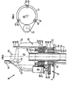
- Reference 1 designates an auxiliary buoy which must be assembled with a main buoy 2.
- Such an arrangement is encountered, for example, when a production column, supported by an auxiliary buoy, must be tensioned by a main buoy.
- the main buoy can be brought to the auxiliary buoy by ballasting.
- the column is tensioned after assembling the two buoys by deballasting the main buoy.
- the approach phase of the main buoy 2 towards the auxiliary buoy may use guide lines 3 fixed to the auxiliary buoy by crossing right through the main buoy through passages 5.
- fingers 6 can be used. allow a precise final approach to the buoys; these fingers can cooperate with the end of the passages 5.
- the assembly of the auxiliary buoy 1 and the main buoy 2 is done by oblong assembly elements 7.
- the assembly element 7 is fixed on one side to the auxiliary buoy 1 by means of anchoring means 8 and on the other side to the main buoy by means of locking means 9.
- the assembly device according to the invention also includes tensioning means 10.
- FIGS 2 and 3 show an embodiment of the anchoring means.
- Figure 2 shows the anchoring means in the non-anchored position and Figure 3 in the anchored position.
- anchoring means comprise a receptacle 11 secured to the auxiliary buoy 2.
- This receptacle comprises a housing 12.
- a profile 13 is produced inside the housing 12.
- This profile can be sinusoidal, sawtooth or any other shape, as soon as it allows the attachment of a complementary shape.
- the end 14 of the oblong assembly element 2 is hollow, and includes a locking member such as a piston 15, as well as openings in which dogs 16 are provided. dogs 16 have, on at least part of their external faces, a profile complementary to that 13, produced inside the housing 12.
- the piston 15 has a position shown in FIG. 3 for which it applies the dogs 16 against the profile 13 produced in the receptacle 11, thus achieving an anchoring of the end 14 of the oblong assembly element 7.
- the piston has the shape of two cylinders 17 and 18 of different diameters.
- the piston 15 may be placed in the position corresponding to the locking of the dogs by the pressurization of the part of the oblong assembly element located above the piston.
- the connecting element 7 must include a passage allowing the pressurization of the compartment located above the piston.
- the assembly element 7 may be hollow over its entire length. This passage can then be used to recover the piston by a fishing tool suspended from a line. This tool can cooperate with the orifice 19 arranged at the top of the piston.
- FIG. 4 represents a section of the anchoring means 8 along the line AA of FIG. 3.
- FIG. 5 represents the tensioning means 20 and the locking means 21.
- the reference 22 designates the top of the main buoy 2 and the reference 23 the passage arranged in the main buoy and which is crossed by the oblong connecting element 7 which, in the case of the example shown, comprises a tube.
- the tensioning means comprise a base 24 bearing on the top 22 of the main buoy.
- jacks 25, 26 are supported on a table 27 arranged on this base.
- a connector 28 comprising jaws 29 makes it possible to grasp a collar 30 integral with the upper end of the oblong assembly element 7.
- the connector 28 has a surface 31 which can bear on the jacks 25 and 26.
- the base 24 may comprise a sleeve 32 of the upper end of the assembly element 7.
- the locking means 21 comprise a threaded zone 33 arranged at the upper end of the oblong connecting element 7, but under the collar 30, a nut 34 cooperating with said thread and means for screwing or unscrewing said nut 34 to distance.
- These means comprise, in the embodiment shown in FIG. 6, a hydraulic motor 35 possibly connected to the surface by cables 36. These cables making it possible to supply the motor 35 with energy from the surface.
- the motor 35 has an axis 37 used to drive a toothed wheel 38 cooperating with teeth 39 integral with the periphery of the nut 34.
- the connector 28 can be connected to the surface by a suspension tube 40 and actuated by control lines 41 also connected to the surface.
- control lines as well as the cables serving to power the motor 35 can be grouped together in an umbilical tube 42.
- this tube may include other lines, connecting the base 24, or elements that it supports to the surface, in particular the hydraulic lines 43 supplying the cylinders 25 and 26.
- each of these rods has an intermediate stop that can slide on these rods. These intermediate stops are supported on the upper face of the connector 28.
- intermediate stops 50, 51 and 52 can be replaced by another equivalent means, such as for example, a single annular stop.
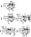
- the two buoys being brought closer to each other in the manner indicated above thanks in particular to the guide lines 3 and the guide fingers 6 and, optionally, to acoustic distance sensors, the oblong assembly elements 7 descended through the passages 23.
- the nut 34 can support the base 24 on its upper face 45.
- the position of the nut on the threaded zone 33 can be such that the jacks 25 and 26 are in bottom stop and in contact with the bearing surface 31 of the connector as shown in FIG. 7. This is not compulsory and it can be assumed that there is a free space between the jacks 25 and 26 and the bearing face 31 of the connector 28.
- the connector 28 can be connected to the surface by tube 42 once the anchoring means 14 are in place in the receptacle 11.
- the piston 15 is introduced into the locking position shown in FIG. 3. This piston 15 can either be lowered from the surface through the tube 42 and the oblong assembly element 7 itself, or be in the position of the figure. 2 from the start of the anchoring operation.
- the piston 15 may possibly be pumped to reach its locking position.
- the jacks 25 and 26 are activated by sending pressurized fluid into the chambers 46 of the jacks by the hydraulic line or lines 43. In doing so, the pistons of the jacks tension the oblong assembly element, since the jacks bearing on the base 24 which itself bears on the top 22 of the buoy 2 push the connector 28 thanks to the bearing surfaces 31.
- the connector 28 puts the elongated assembly element 7 under tension. This is illustrated in FIG. 8.
- the motor 35 (see FIG. 8) is activated in the appropriate direction required to apply the nut 34 on the support top 22 of the buoy 2, by means of the toothed wheel 38 (see FIG. 9).
- the motor 35 can, for example, be a hydraulic motor.
- the suspension tube 40 is removed. It drives with it the connector 28 which brings the sliding stops 50, 51 and 52 into contact with the fixed stops 47, 48 and 49 and therefore thanks to the rods 44 the base 24 as well as the equipment which it supports, in particular the motor 35 and the cylinders 25 and 26 are raised to the surface (see Figure 11).
- the oblong connecting elements remain in place and hold the two buoys together.
- the procedure is the opposite of that previously exposed.
- the pistons 15 are recovered using the orifice 19 and a recovery line.
- tensioning effect exerted on the assembly element 7 may be greater than or equal to the force which tends in certain applications to separate the two members to be assembled.
Landscapes
- Engineering & Computer Science (AREA)
- Mechanical Engineering (AREA)
- Mining & Mineral Resources (AREA)
- Life Sciences & Earth Sciences (AREA)
- Geology (AREA)
- General Engineering & Computer Science (AREA)
- Physics & Mathematics (AREA)
- Environmental & Geological Engineering (AREA)
- Fluid Mechanics (AREA)
- General Life Sciences & Earth Sciences (AREA)
- Geochemistry & Mineralogy (AREA)
- Actuator (AREA)
- Mechanical Control Devices (AREA)
- Underground Structures, Protecting, Testing And Restoring Foundations (AREA)
- Devices For Conveying Motion By Means Of Endless Flexible Members (AREA)
- Cleaning Or Clearing Of The Surface Of Open Water (AREA)
- Prostheses (AREA)
- Handcart (AREA)
- Radar Systems Or Details Thereof (AREA)
Abstract
Description
La présente invention concerne un dispositif d'assemblage à distance de deux organes.The present invention relates to a device for the remote assembly of two members.
Il est souvent nécessaire d'assembler à distance deux organes, de manière qu'ils soient fortement appliqués l'un à l'autre, notamment en milieu marin.It is often necessary to assemble two organs at a distance, so that they are strongly applied to each other, especially in the marine environment.
Une telle opération est difficilement réalisable par des plongeurs du fait de l'absence de point d'appui dans l'eau. Dans d'autres cas une telle opération ne peut pas être envisagée parce qu'elle se déroule dans des milieux ou l'homme ne peut pas intervenir.Such an operation is difficult to achieve by divers due to the absence of a fulcrum in the water. In other cases such an operation cannot be envisaged because it takes place in environments where man cannot intervene.
L'art antérieur peut être illustré par le brevet européen EP-A 0 024 180, le brevet français FR-A 2 475 674, le brevet américain US-A 4 297 965 et la demande de brevet EP-A 0 116 488.The prior art can be illustrated by the European patent EP-A 0 024 180, the French patent FR-A 2 475 674, the American patent US-A 4 297 965 and the patent application EP-A 0 116 488.
La demande de brevet EP-A 0 024 180 décrit un dispositif d'ancrage pour la connexion sous marine d'une conduite avec une tête de puits. Ce dispositif d'ancrage comporte deux segments mobiles et circonférentiels ayant des portées inclinées s'appuyant sur d'autres parties inclinées solidaires d'un guide. Un piston hydraulique réalise une translation entre les segments et le guide et du fait des portées inclinées produit une dilatation des segments et l'ancrage du guide à l'intérieur d'une tête de puits.Patent application EP-A 0 024 180 describes an anchoring device for the underwater connection of a pipe with a well head. This anchoring device comprises two mobile and circumferential segments having inclined bearing surfaces supported by other inclined parts integral with a guide. A hydraulic piston translates between the segments and the guide and, due to the inclined bearing surfaces, expands the segments and anchors the guide inside a well head.
La demande de brevet FR-A 2 475 674 décrit un appareil commandé à distance permettant de visser les vis pour assembler un couvercle avec la cuve d'un réacteur sous pression.Patent application FR-A 2 475 674 describes a device controlled remotely making it possible to tighten the screws to assemble a cover with the tank of a pressure reactor.
Le brevet US-A 4 297 965 décrit une structure sous-marine comportant une bouée retenue du fond de l'eau par des éléments tubulaires fixés à des moyens d'arrimage disposés au fond de l'eau.US-A 4,297,965 describes an underwater structure comprising a buoy retained from the bottom of the water by tubular elements fixed to lashing means disposed at the bottom of the water.
La demande de brevet EP-A 0 116 488 décrit un appareil de vissage-dévissage des goujons de fixation du couvercle de la cuve d'un réacteur nucléaire et de vissage et de dévissage des écrous de serrage du couvercle. Cet appareil comporte des moyens de prétension de la tête d'un goujon, des moyens de levage et de traction de la tête de goujon adaptés à lever, abaisser ou à mettre en extension des goujons, des moyens de vissage et dévissage du goujon, des moyens de vissage et dévissage de l'écrou. L'appareil réalise le serrage du couvercle du réacteur sur la cuve en vissant un goujon dans la cuve, en tirant sur le goujon, en vissant l'écrou sur le goujon, et en relachant la traction sur le goujon. L'ancrage des goujons dans la cuve est obtenu par le vissage du goujon dans la cuve.Patent application EP-A 0 116 488 describes an apparatus for screwing-unscrewing the studs for fixing the cover of the vessel of a nuclear reactor and for screwing and unscrewing the tightening nuts of the cover. This device comprises means for pretensioning the head of a stud, means for lifting and pulling the head of stud adapted to raise, lower or extend the studs, means for screwing and unscrewing the stud, means for screwing and unscrewing the nut. The apparatus tightens the reactor cover on the tank by screwing a stud into the tank, pulling on the stud, screwing the nut on the stud, and releasing the traction on the stud. The anchoring of the studs in the tank is obtained by screwing the stud into the tank.
La présente invention fournit un dispositif d'assemblage à distance de deux organes à l'aide d'au moins un élément d'assemblage oblong, le dispositif comportant des moyens d'ancrage du dit élément d'assemblage sur un premier desdits organes, des moyens de tensionnement télécommandés dudit élément d'assemblage et les moyens de verrouillage dudit élément d'assemblage sur le deuxième organe, les moyens d'ancrage comportant un corps solidaire de l'élément d'assemblage. Le dispositif selon la présente invention se caractérise en ce que ledit corps comporte au moins un chien adapté à coopérer avec un profil solidaire d'un réceptacle qui est lui-même solidaire du premier organe, ledit corps se logeant au moins partiellement dans ledit réceptacle, ledit corps étant creux et comportant un piston adapté à coulisser dans ce corps, ce piston pouvant occuper une position pour laquelle il verrouille ledit chien dans ledit profil.The present invention provides a device for the remote assembly of two organs using at least one oblong assembly element, the device comprising means for anchoring said assembly element on a first of said organs, remotely controlled tensioning means of said assembly element and the locking means of said assembly element on the second member, the anchoring means comprising a body integral with the assembly element. The device according to the present invention is characterized in that said body comprises at least one dog adapted to cooperate with a profile secured to a receptacle which is itself secured to the first member, said body being housed at least partially in said receptacle, said body being hollow and comprising a piston adapted to slide in this body, this piston being able to occupy a position for which it locks said dog in said profile.
L'élément d'assemblage pourra être creux et le piston pourra comporter une tête de repêchage.The assembly element may be hollow and the piston may include a recovery head.
Les moyens de tensionnement pourront comporter au moins un vérin.The tensioning means may include at least one jack.
Les moyens de verrouillage pourront comporter une zone filetée à l'extrémité de l'élément d'assemblage oblong, et un écrou coopérant avec ladite zone filetée, cet écrou prenant appui sur le deuxième organe.The locking means may include a threaded zone at the end of the oblong assembly element, and a nut cooperating with said threaded zone, this nut bearing on the second member.
Les moyens de verrouillage pourront comporter un moteur dont l'axe est équipé d'une roue dentée adaptée à coopérer avec des dents, aménagées sur la face externe dudit écrou.The locking means may include a motor whose axis is equipped with a toothed wheel adapted to cooperate with teeth, arranged on the external face of said nut.
Les moyens de tensionnement pourront comporter un socle reposant sur le deuxième organe, des vérins et un connecteur, ce connecteur étant adapté à saisir l'extrémité dudit élément d'assemblage oblong, lesdits vérins prenant appui entre ledit socle et ledit connecteur.The tensioning means may include a base resting on the second member, jacks and a connector, this connector being adapted to grip the end of said oblong assembly element, said jacks being supported between said base and said connector.
Ce socle pourra comporter des tiges sur lesquelles pourront coulisser des butées, ces tiges pourront comporter également des butées fixes limitant la course des butées coulissantes.This base may include rods on which can slide stops, these rods may also include fixed stops limiting the travel of the sliding stops.
Les moyens de verrouillage pourront comporter un moteur reposant sur le socle.The locking means may include a motor resting on the base.
La présente invention sera mieux comprise et ses avantages apparaîtront plus clairement à la description qui suit d'un exemple particulier, nullement limitatif, illustré par les figures ci-annexées, parmi lesquelles :
- - la figure 1 représente schématiquement l'ensemble du dispositif selon l'invention appliqué à l'assemblage de deux bouées, ce dispositif comporte des moyens d'ancrage, des moyens de tensionnement et des moyens de verrouillage,
- - lés figures 2, 3 et 4 illustrent d'une manière plus détaillée les moyens d'ancrage, la figure 4 étant une vue en coupe de la figure 3,
- - les figures 5 et 6 représente les moyens de tensionnement et de verrouillage, la figure 6 étant une vue du dessus de la figure 5, et
- - les figures 7 à 11 montrent différentes phases de mise en oeuvre du dispositif selon l'invention.
- FIG. 1 diagrammatically represents the entire device according to the invention applied to the assembly of two buoys, this device comprises anchoring means, tensioning means and locking means,
- FIGS. 2, 3 and 4 illustrate in more detail the anchoring means, FIG. 4 being a sectional view of FIG. 3,
- FIGS. 5 and 6 represent the tensioning and locking means, FIG. 6 being a top view of FIG. 5, and
- - Figures 7 to 11 show different phases of implementation of the device according to the invention.
L'exemple particulier décrit ci-après concerne l'assemblage de deux bouées dans un milieu marin.The particular example described below concerns the assembly of two buoys in a marine environment.
La référence 1 désigne une bouée auxiliaire qui doit être assemblée à une bouée principale 2.Reference 1 designates an auxiliary buoy which must be assembled with a
Un tel agencement se rencontre, par exemple, lorsqu'une colonne de production, supportée par une bouée auxiliaire, doit être mise en tension par une bouée principale.Such an arrangement is encountered, for example, when a production column, supported by an auxiliary buoy, must be tensioned by a main buoy.
La bouée principale peut être amenée vers la bouée auxiliaire par ballastage. La mise en tension de la colonne se faisant après assemblage des deux bouées par le déballastage de la bouée principale.The main buoy can be brought to the auxiliary buoy by ballasting. The column is tensioned after assembling the two buoys by deballasting the main buoy.
La phase d'approche de la bouée principale 2 vers la bouée auxiliaire, pourra utiliser des lignes guides 3 fixées à la bouée auxiliaire en 4 traversant de part en part la bouée principale à travers des passages 5.The approach phase of the
De plus dans la phase finale du rapprochement des deux bouées on peut utiliser des doigts 6 qui . permettront une approche finale précise des bouées ; ces doigts pourront coopérer avec l'extrémité des passages 5.In addition, in the final phase of bringing the two buoys together,
L'assemblage de la bouée auxiliaire 1 et de la bouée principale 2 se fait par des éléments d'assemblage oblongs 7. L'élément d'assemblage 7 est fixé d'un côté à la bouée auxiliaire 1 grâce à des moyens d'ancrage 8 et de l'autre côté à la bouée principale grâce à des moyens de verrouillage 9.The assembly of the auxiliary buoy 1 and the
Le dispositif d'assemblage selon t'invention comporte également des moyens de tensionnement 10.The assembly device according to the invention also includes tensioning means 10.
Les figures 2 et 3 représentent un mode de réalisation des moyens d'ancrage.Figures 2 and 3 show an embodiment of the anchoring means.
La figure 2 représente les moyens d'ancrage en position non ancrée et la figure 3 en position ancrée.Figure 2 shows the anchoring means in the non-anchored position and Figure 3 in the anchored position.
Ces moyens d'ancrage comportent un réceptacle 11 solidaire de la bouée auxiliaire 2. Ce réceptacle comporte un logement 12. Un profil 13 est réalisé à l'intérieur du logement 12.These anchoring means comprise a
Ce profil peut être sinusoidal, en dents de scie ou de tout autre forme, dès l'instant que celle-ci permet l'accrochage d'une forme complémentaire.This profile can be sinusoidal, sawtooth or any other shape, as soon as it allows the attachment of a complementary shape.
Dans le cas représenté aux figures 2 et 3 l'extrémité 14 de l'élément d'assemblage oblong 2 est creux, et comporte un organe de verrouillage tel un piston 15, ainsi que des ouvertures dans lesquelles sont dispo sés des chiens 16. Les chiens 16 comportent sur une partie au moins de leurs faces extérieures un profil complémentaire de celui l3,réalisé à l'intérieur du logement 12.In the case shown in FIGS. 2 and 3, the
Le piston 15 possède une position représentée à la figure 3 pour laquelle il applique les chiens 16 contre le profil 13 réalisé dans le réceptacle 11, réalisant ainsi un ancrage de l'extrémité 14 de l'élément d'assemblage oblong 7.The piston 15 has a position shown in FIG. 3 for which it applies the
Dans l'exemple représenté aux figures 2 et 3 le piston possède une forme de deux cylindres 17 et 18 de diamètres différents.In the example shown in Figures 2 and 3 the piston has the shape of two
Lorsque les chiens sont dans la position dite "libre" représentée à la figure 2, ils s'appliquent sur le cylindre 17 de plus petit diamètre. Lorsque les chiens sont dans la position de verrouillage représentée à la figure 2 ils s'appliquent sur le cylindre 18 de plus grand diamètre.When the dogs are in the so-called "free" position shown in FIG. 2, they are applied to the cylinder 17 of smaller diameter. When the dogs are in the locking position shown in Figure 2 they apply to the
Le piston 15 pourra être placé dans la position correspondant au verrouillage des chiens par la mise en pression de la partie de l'élément d'assemblage oblong se trouvant au-dessus du piston. Bien entendu dans ce cas l'élément d'assemblage 7 devra comporter un passage permettant la mise en pression du compartiment se trouvant au-dessus du piston.The piston 15 may be placed in the position corresponding to the locking of the dogs by the pressurization of the part of the oblong assembly element located above the piston. Of course in this case the connecting
Par exemple l'élément d'assemblage 7 pourra être creux sur toute sa longueur. Ce passage pourra alors, être utilisé pour récupérer le piston par un outil de repêchage suspendu à une ligne. Cet outil pourra coopérer avec l'orifice 19 aménagé au sommet du piston.For example, the
La figure 4 représente une coupe des moyens d'ancrage 8 suivant la ligne AA de la figure 3.FIG. 4 represents a section of the anchoring means 8 along the line AA of FIG. 3.
La figure 5 représente les moyens de tensionnement 20 et les moyens de verrouillage 21.FIG. 5 represents the tensioning means 20 and the locking means 21.
La référence 22 désigne le sommet de la bouée principale 2 et la référence 23 le passage aménagé dans la bouée principale et qui est traversé par l'élément d'assemblage oblong 7 qui, dans le cas de l'exemple représenté, comporte un tube.The
Dans le cas de la figure 5, les moyens de tensionnement comportent un socle 24 prenant appui sur le sommet 22 de la bouée principale.In the case of Figure 5, the tensioning means comprise a
Plusieurs vérins 25, 26 prennent appui sur une table 27 aménagée sur ce socle.
Un connecteur 28 comportant des machoires 29 permet de saisir un collet 30 solidaire de l'extrémité supérieure de l'élément d'assemblage oblong 7.A
Le connecteur 28 possède une surface 31 pouvant prendre appui sur les vérins 25 et 26.The
Le socle 24 peut comporter un manchon 32 de l'extrémité supérieure de l'élément d'assemblage 7.The base 24 may comprise a
Les moyens de verrouillage 21 comportent une zone filetée 33 aménagée à l'extrémité supérieure de l'élément d'assemblage oblong 7, mais sous le collet 30, un écrou 34 coopérant avec ledit filet et des moyens pour visser ou dévisser ledit écrou 34 à distance. Ces moyens comportent, dans le mode de réalisation représenté à la figure 6, un moteur hydraulique 35 éventuellement relié à la surface par des câbles 36. Ces câbles permettant d'alimenter le moteur 35 en énergie depuis la surface.The locking means 21 comprise a threaded
Le moteur 35 comporte un axe 37 servant à entraîner une roue dentée 38 coopérant avec des dents 39 solidaires de la périphérie de l'écrou 34.The
Le connecteur 28 peut être reliée à la surface par un tube de suspen sion 40 et actionné par des lignes de commande 41 également reliées à la surface.The
Ces lignes de commande ainsi que les câbles servant à alimenter le moteur 35 peuvent être regroupés ensemble dans un tube ombilical 42. D'ailleurs ce tube pourra comporter d'autres lignes, reliant le socle 24, ou des éléments qu'il supporte à la surface, notamment les canalisations hydrauliques 43 d'alimentation des vérins 25 et 26.These control lines as well as the cables serving to power the
On remarquera sur la figure 5 et/ou la figure 6, qui est une vue du dessus partielle de la figure 5, la présence de tiges 44 fixées au socle 24 à l'une de leurs extrémités et comportant une butée fixe 47, 48 et 49 à l'autre extrémité.Note in Figure 5 and / or Figure 6, which is a partial top view of Figure 5, the presence of
En outre, chacune de ces tiges comporte une butée intermédiaire pouvant coulisser sur ces tiges. Ces butées intermédiaires prennent appui sur la face supérieure du connecteur 28.In addition, each of these rods has an intermediate stop that can slide on these rods. These intermediate stops are supported on the upper face of the
Il est bien entendu que les butées intermédiaires 50, 51 et 52 peuvent être remplacées par un autre moyen équivalent, tel par exemple, une seule butée annulaire.It is understood that the intermediate stops 50, 51 and 52 can be replaced by another equivalent means, such as for example, a single annular stop.
Un exemple de la mise en oeuvre du dispositif selon l'invention est décrit ci-après.An example of the implementation of the device according to the invention is described below.
Les deux bouées étant rapprochées l'une de l'autre de la manière indiquée précédemment grâce, notamment, aux lignes guides 3 et aux doigts de guidage 6 et, éventuellement, à des capteurs accousti- ques de distance, les éléments d'assemblage oblong 7 sont descendus à travers les passages 23.The two buoys being brought closer to each other in the manner indicated above thanks in particular to the guide lines 3 and the
Lors de cette descente l'élément d'assemblage oblong 7 est suspendu au connecteur 28 grâce au collet 30.During this descent the
L'écrou 34 pourra supporter le socle 24 sur sa face superieure 45.The
La position de l'écrou sur la zone filetée 33 peut être telle que les vérins 25 et 26 soient en butée basse et au contact de la surface d'appui 31 du connecteur comme représenté à la figure 7. Ceci n'est pas obligatoire et l'on peut admettre qu'il y ait un espace libre entre les vérins 25 et 26 et la face d'appui 31 du connecteur 28.The position of the nut on the threaded
Le connecteur 28 peut être relié à la surface par tube 42 une fois les moyens d'ancrage 14 en place dans le réceptacle 11.The
Le piston 15 est introduit dans la position de verrouillage représentée à la figure 3. Ce piston 15 pourra être soit descendu depuis la surface à travers le tube 42 et l'élément d'assemblage oblong 7 luimême, soit être dans la position de la figure 2 dés le début de l'opération d'ancrage.The piston 15 is introduced into the locking position shown in FIG. 3. This piston 15 can either be lowered from the surface through the
Le piston 15 pourra être éventuellement pompé pour atteindre sa position de verrouillage.The piston 15 may possibly be pumped to reach its locking position.
Une fois cet ancrage réalisé les vérins 25 et 26 sont activés en envoyant du fluide sous pression dans les chambres 46 des vérins par la ou les lignes hydrauliques 43. Ce faisant les pistons des vérins mettent en tension l'élément d'assemblage oblong, puisque les vérins prenant appui sur le socle 24 qui prend lui-même appui sur le sommet 22 de la bouée 2 poussent le connecteur 28 grâce aux surfaces d'appui 31.Once this anchoring has been achieved, the
Par l'intermédiaire de ses machoires 29 le connecteur 28 met en tension l'élément d'assemblage allongé 7. Ceci est illustré à la figure 8.Via its
Lorsque la tension souhaitée de l'élément d'assemblage oblong est atteinte, le moteur 35 (voir figure 8) est activé dans le sens appro prié pour appliquer l'écrou 34 sur le sommet d'appui 22 de la bouée 2, grâce à la roue dentée 38 (voir figure 9). Le moteur 35 peut, par exemple, être un moteur hydraulique.When the desired tension of the oblong connecting element is reached, the motor 35 (see FIG. 8) is activated in the appropriate direction required to apply the
Cela étant réalisé, la pression dans la chambre 46 des vérins est abaissée, ce qui libère le connecteur 28. Lors de cette opération les efforts de maintien en tension de l'élément d'assemblage oblong 7 sont transférés sur l'écrou 34. (voir figure 10). Les machoires 29 du connecteur 28 peuvent être relachées.This being done, the pressure in the
Le tube de suspension 40 est retiré. Il entraîne avec lui le connecteur 28 qui amène les butées coulissantes 50, 51 et 52 au contact des butées fixes 47, 48 et 49 et donc grâce aux tiges 44 le socle 24 ainsi que les équipements qu'il supporte, notamment le moteur 35 et les vérins 25 et 26 sont remontés à la surface (voir figure 11).The
Les éléments d'assemblage oblongs restent en place et maintiennent ensemble les deux bouées. Pour le démontage des éléments d'assemblage oblong on procède de la manière inverse de celle exposée précédemment.The oblong connecting elements remain in place and hold the two buoys together. For the dismantling of the oblong assembly elements, the procedure is the opposite of that previously exposed.
Les pistons 15 sont repêchés grâce à l'orifice 19 et à une ligne de repêchage.The pistons 15 are recovered using the
Il est bien évident que l'effet de tensionnement exercé sur l'élément d'assemblage 7 pourra être supérieur ou égal à l'effort qui tend dans certaines applications, à désolidariser les deux organes à assembler.It is obvious that the tensioning effect exerted on the
Claims (9)
Applications Claiming Priority (2)
| Application Number | Priority Date | Filing Date | Title |
|---|---|---|---|
| FR8507583A FR2582047B1 (en) | 1985-05-17 | 1985-05-17 | DEVICE FOR THE REMOTE ASSEMBLY OF TWO ORGANS |
| FR8507583 | 1985-05-17 |
Publications (2)
| Publication Number | Publication Date |
|---|---|
| EP0203003A1 EP0203003A1 (en) | 1986-11-26 |
| EP0203003B1 true EP0203003B1 (en) | 1989-07-26 |
Family
ID=9319413
Family Applications (1)
| Application Number | Title | Priority Date | Filing Date |
|---|---|---|---|
| EP86401038A Expired EP0203003B1 (en) | 1985-05-17 | 1986-05-15 | Remotely-controlled assembling device for two items |
Country Status (7)
| Country | Link |
|---|---|
| US (1) | US4984527A (en) |
| EP (1) | EP0203003B1 (en) |
| JP (1) | JPH0650122B2 (en) |
| CA (1) | CA1303432C (en) |
| ES (1) | ES8703960A1 (en) |
| FR (1) | FR2582047B1 (en) |
| NO (1) | NO171378C (en) |
Families Citing this family (9)
| Publication number | Priority date | Publication date | Assignee | Title |
|---|---|---|---|---|
| GB2267943A (en) * | 1992-06-12 | 1993-12-22 | Pilgrim Moorside Ltd | Securing parts together by bolts or studs |
| US5398574A (en) * | 1992-12-23 | 1995-03-21 | Unex Corporation | Fluid operating tool |
| US5431512A (en) * | 1993-12-28 | 1995-07-11 | Mcdermott International, Inc. | Flex tube compliant offshore structure |
| GB9411384D0 (en) * | 1994-06-07 | 1994-07-27 | Hedley Purvis Ltd | Method of tensioning and de-tensioning a bolt |
| GB2375264B (en) * | 2001-05-02 | 2004-10-13 | Mitel Knowledge Corp | Remote assembly of messages for distributed applications |
| CN103935479B (en) * | 2014-05-12 | 2016-06-08 | 江苏科技大学 | The flexible mechanical formula junctor being applied between very large floating structures module |
| EP3728876B1 (en) * | 2017-12-20 | 2023-05-17 | Superbolt, Inc. | Multiple chamber hydraulic multi-jack bolt tensioners |
| RU2674591C1 (en) * | 2018-03-27 | 2018-12-11 | Публичное акционерное общество "Татнефть" имени В.Д. Шашина | Column heads turning device |
| CN113753186B (en) * | 2021-09-04 | 2022-07-05 | 杭州西湖喷泉设备成套有限公司 | Fault cooperation processing method, system and storage medium for floating water show platform |
Family Cites Families (8)
| Publication number | Priority date | Publication date | Assignee | Title |
|---|---|---|---|---|
| US928536A (en) * | 1907-10-21 | 1909-07-20 | Giuseppe Pino | Apparatus for elevating submerged vessels. |
| US3722585A (en) * | 1971-01-12 | 1973-03-27 | Vetco Offshore Ind Inc | Apparatus for aligning and connecting underwater flowlines |
| US4216834A (en) * | 1976-10-28 | 1980-08-12 | Brown Oil Tools, Inc. | Connecting assembly and method |
| US4391331A (en) * | 1979-08-10 | 1983-07-05 | Constructors John Brown Limited | Guides for use in forming pipe connections and a process of forming pipe connections |
| US4297965A (en) * | 1979-09-06 | 1981-11-03 | Deep Oil Technology, Inc. | Tension leg structure for tension leg platform |
| DE8003492U1 (en) * | 1980-02-09 | 1980-05-22 | Kloeckner-Becorit Gmbh, 4620 Castrop- Rauxel | REMOTE CONTROLLED SCREWDRIVER FOR THE SCREWS OF THE LID SCREWING OF A REACTOR PRESSURE TANK |
| US4540314A (en) * | 1982-03-25 | 1985-09-10 | Fluor Subsea Services, Inc. | Tension leg means and method of installing same for a marine platform |
| US4491439A (en) * | 1982-07-26 | 1985-01-01 | Hughes Tool Company | Tendon latch |
-
1985
- 1985-05-17 FR FR8507583A patent/FR2582047B1/en not_active Expired
-
1986
- 1986-05-15 EP EP86401038A patent/EP0203003B1/en not_active Expired
- 1986-05-15 NO NO861940A patent/NO171378C/en unknown
- 1986-05-16 CA CA000509403A patent/CA1303432C/en not_active Expired - Lifetime
- 1986-05-16 JP JP61110971A patent/JPH0650122B2/en not_active Expired - Lifetime
- 1986-05-16 ES ES555063A patent/ES8703960A1/en not_active Expired
-
1988
- 1988-08-25 US US07/236,447 patent/US4984527A/en not_active Expired - Fee Related
Also Published As
| Publication number | Publication date |
|---|---|
| CA1303432C (en) | 1992-06-16 |
| US4984527A (en) | 1991-01-15 |
| ES8703960A1 (en) | 1987-03-01 |
| JPH0650122B2 (en) | 1994-06-29 |
| FR2582047A1 (en) | 1986-11-21 |
| NO861940L (en) | 1986-11-18 |
| ES555063A0 (en) | 1987-03-01 |
| NO171378C (en) | 1993-03-03 |
| FR2582047B1 (en) | 1988-04-08 |
| EP0203003A1 (en) | 1986-11-26 |
| JPS61266805A (en) | 1986-11-26 |
| NO171378B (en) | 1992-11-23 |
Similar Documents
| Publication | Publication Date | Title |
|---|---|---|
| EP0203003B1 (en) | Remotely-controlled assembling device for two items | |
| FR2556065A1 (en) | MECHANICAL CONNECTION DEVICE | |
| EP2576414B1 (en) | Device for gripping and adjusting the tension of an elongate element such as a cable, rope or the like | |
| EP0052672A1 (en) | Method for recovering a retrievable core receiver in upward drilling and a recovery head for this purpose | |
| EP4093666B1 (en) | Cambering device for profiled sail | |
| CA1320396C (en) | Component part of a catenary anchor line, anchor line comprising such component part, and device and process for implementing such anchor line | |
| FR2604414A1 (en) | INTERVENTION DEVICE FOR HORIZONTALLY INSTALLING AND REMOVING EQUIPMENT ON A UNDERWATER UNIT | |
| WO1996000359A1 (en) | Device for laying flexible conduits from a floating support | |
| FR2474432A1 (en) | ANCHOR DEVICE FOR MARINE ANCHOR ROD | |
| EP0294252B1 (en) | Equipment for a drill string with a side entry sub and method for its use | |
| FR2463040A1 (en) | HYDRAULIC STEERING IN CREMAILLERE | |
| CA1301637C (en) | Remote anchoring and tensioning system for an elongated element | |
| FR2578180A1 (en) | Hydraulic vice with rapid approach | |
| CA1074583A (en) | Subsea anchoring device | |
| FR2723975A1 (en) | OIL PLATFORM FOR DRILLING OR EXPLOITATION AT SEA, PROVIDED WITH IMPROVED MEANS OF ANCHORING IN THE MARINE SOIL. | |
| FR2594406A1 (en) | Device for rapid casting off and recovery of a mooring especially for an oil platform | |
| FR2525682A1 (en) | DISCONNECT TOOL OF THE LINE-GUIDE CONNECTOR AND METHOD FOR IMPLEMENTING IT | |
| FR2559085A2 (en) | Device allowing a workpiece to be machined to be held in a predetermined position with respect to a machine tool upon which this device may be fixed | |
| FR2776305A1 (en) | Lance carrier incorporating a multifunctional securing head | |
| FR2665490A1 (en) | VALVE MANEUVER ASSEMBLY. | |
| FR2741038A1 (en) | DEVICE FOR DREADING MINES WITH ANCHORING CABLE | |
| EP0270458A1 (en) | Ground drilling device working along a substantially horizontal axis | |
| FR2577612A1 (en) | Fixing mechanism for a corer which can be raised through the inside of the rods | |
| FR2766229A1 (en) | Ground loading test probe | |
| FR2644152A1 (en) | Device for tearing up posts, vertical piles and the like |
Legal Events
| Date | Code | Title | Description |
|---|---|---|---|
| PUAI | Public reference made under article 153(3) epc to a published international application that has entered the european phase |
Free format text: ORIGINAL CODE: 0009012 |
|
| AK | Designated contracting states |
Kind code of ref document: A1 Designated state(s): FR GB NL |
|
| 17P | Request for examination filed |
Effective date: 19870318 |
|
| 17Q | First examination report despatched |
Effective date: 19880113 |
|
| GRAA | (expected) grant |
Free format text: ORIGINAL CODE: 0009210 |
|
| AK | Designated contracting states |
Kind code of ref document: B1 Designated state(s): FR GB NL |
|
| GBT | Gb: translation of ep patent filed (gb section 77(6)(a)/1977) | ||
| PLBE | No opposition filed within time limit |
Free format text: ORIGINAL CODE: 0009261 |
|
| STAA | Information on the status of an ep patent application or granted ep patent |
Free format text: STATUS: NO OPPOSITION FILED WITHIN TIME LIMIT |
|
| 26N | No opposition filed | ||
| PGFP | Annual fee paid to national office [announced via postgrant information from national office to epo] |
Ref country code: FR Payment date: 19960409 Year of fee payment: 11 |
|
| PGFP | Annual fee paid to national office [announced via postgrant information from national office to epo] |
Ref country code: GB Payment date: 19960422 Year of fee payment: 11 |
|
| PGFP | Annual fee paid to national office [announced via postgrant information from national office to epo] |
Ref country code: NL Payment date: 19960531 Year of fee payment: 11 |
|
| PG25 | Lapsed in a contracting state [announced via postgrant information from national office to epo] |
Ref country code: GB Effective date: 19970515 |
|
| PG25 | Lapsed in a contracting state [announced via postgrant information from national office to epo] |
Ref country code: NL Effective date: 19971201 |
|
| GBPC | Gb: european patent ceased through non-payment of renewal fee |
Effective date: 19970515 |
|
| PG25 | Lapsed in a contracting state [announced via postgrant information from national office to epo] |
Ref country code: FR Free format text: LAPSE BECAUSE OF NON-PAYMENT OF DUE FEES Effective date: 19980130 |
|
| NLV4 | Nl: lapsed or anulled due to non-payment of the annual fee |
Effective date: 19971201 |
|
| REG | Reference to a national code |
Ref country code: FR Ref legal event code: ST |