EP0202788A2 - Tyre - Google Patents
Tyre Download PDFInfo
- Publication number
- EP0202788A2 EP0202788A2 EP86303082A EP86303082A EP0202788A2 EP 0202788 A2 EP0202788 A2 EP 0202788A2 EP 86303082 A EP86303082 A EP 86303082A EP 86303082 A EP86303082 A EP 86303082A EP 0202788 A2 EP0202788 A2 EP 0202788A2
- Authority
- EP
- European Patent Office
- Prior art keywords
- tyre
- tread
- carcass
- pattern
- ply
- Prior art date
- Legal status (The legal status is an assumption and is not a legal conclusion. Google has not performed a legal analysis and makes no representation as to the accuracy of the status listed.)
- Granted
Links
Images


Classifications
-
- B—PERFORMING OPERATIONS; TRANSPORTING
- B60—VEHICLES IN GENERAL
- B60C—VEHICLE TYRES; TYRE INFLATION; TYRE CHANGING; CONNECTING VALVES TO INFLATABLE ELASTIC BODIES IN GENERAL; DEVICES OR ARRANGEMENTS RELATED TO TYRES
- B60C11/00—Tyre tread bands; Tread patterns; Anti-skid inserts
- B60C11/03—Tread patterns
- B60C11/11—Tread patterns in which the raised area of the pattern consists only of isolated elements, e.g. blocks
-
- B—PERFORMING OPERATIONS; TRANSPORTING
- B60—VEHICLES IN GENERAL
- B60C—VEHICLE TYRES; TYRE INFLATION; TYRE CHANGING; CONNECTING VALVES TO INFLATABLE ELASTIC BODIES IN GENERAL; DEVICES OR ARRANGEMENTS RELATED TO TYRES
- B60C11/00—Tyre tread bands; Tread patterns; Anti-skid inserts
-
- B—PERFORMING OPERATIONS; TRANSPORTING
- B60—VEHICLES IN GENERAL
- B60C—VEHICLE TYRES; TYRE INFLATION; TYRE CHANGING; CONNECTING VALVES TO INFLATABLE ELASTIC BODIES IN GENERAL; DEVICES OR ARRANGEMENTS RELATED TO TYRES
- B60C11/00—Tyre tread bands; Tread patterns; Anti-skid inserts
- B60C11/0083—Tyre tread bands; Tread patterns; Anti-skid inserts characterised by the curvature of the tyre tread
-
- B—PERFORMING OPERATIONS; TRANSPORTING
- B60—VEHICLES IN GENERAL
- B60C—VEHICLE TYRES; TYRE INFLATION; TYRE CHANGING; CONNECTING VALVES TO INFLATABLE ELASTIC BODIES IN GENERAL; DEVICES OR ARRANGEMENTS RELATED TO TYRES
- B60C3/00—Tyres characterised by the transverse section
- B60C3/04—Tyres characterised by the transverse section characterised by the relative dimensions of the section, e.g. low profile
-
- B—PERFORMING OPERATIONS; TRANSPORTING
- B60—VEHICLES IN GENERAL
- B60C—VEHICLE TYRES; TYRE INFLATION; TYRE CHANGING; CONNECTING VALVES TO INFLATABLE ELASTIC BODIES IN GENERAL; DEVICES OR ARRANGEMENTS RELATED TO TYRES
- B60C9/00—Reinforcements or ply arrangement of pneumatic tyres
- B60C9/02—Carcasses
- B60C9/0292—Carcass ply curvature
-
- Y—GENERAL TAGGING OF NEW TECHNOLOGICAL DEVELOPMENTS; GENERAL TAGGING OF CROSS-SECTIONAL TECHNOLOGIES SPANNING OVER SEVERAL SECTIONS OF THE IPC; TECHNICAL SUBJECTS COVERED BY FORMER USPC CROSS-REFERENCE ART COLLECTIONS [XRACs] AND DIGESTS
- Y02—TECHNOLOGIES OR APPLICATIONS FOR MITIGATION OR ADAPTATION AGAINST CLIMATE CHANGE
- Y02T—CLIMATE CHANGE MITIGATION TECHNOLOGIES RELATED TO TRANSPORTATION
- Y02T10/00—Road transport of goods or passengers
- Y02T10/80—Technologies aiming to reduce greenhouse gasses emissions common to all road transportation technologies
- Y02T10/86—Optimisation of rolling resistance, e.g. weight reduction
Definitions
- This invention relates to a pneumatic radial ply tyre and in particular to a radial tyre suitable for use for truck, bus, light truck, and other vehicles.
- One object is to provide an improved radial tyre, in which various requirements for this kind of tyre are improved resistance to cutting, resistance to wear, durability in high speed running, low fuel comsumption, and vehicle driving stability are well-balanced with each other and also with good other general characteristics necessary for these tyres such as vehicle ride comfort and traction capacity.
- An object of this invention is to solve the above problems of prior art tyres and to provide an improvement in resistance of the tread crown part to cutting and wear, durability of the tyre in high speed running, savings of fuel consumption, and driving stability without decreasing comfort in vehicle ride or the traction capacity of the tyre.
- a radial tyre comprises:-
- the narrow grooves have a width of not more than 6mm and they are preferably also spaced apart by between 0.1 and 1.1% of the circumference of the tyre at the centre of the tread.
- the narrow grooves may be at 0 0 to 45 0 to the direction of the tyre axial direction.
- the central region and the shoulder regions may each comprise tread ribs or blocks.
- a pneumatic radial ply tyre as claim comprises a tread reinforced by a carcass layer composed of at least a single layer of ply consisting of inextensible or low extensibility cords arranged substantially to lie in the radial direction and with the cords parallel with each other, and a belt layer composed of at least two layers of plies, each consisting of cords, arranged between the carcass layer and the tread rubber, adjacent to the carcass layer, the cord of each ply are small angle to the direction of the tyre circumference, and are parallel with the other cords in each ply.
- the cords of one ply are crossed to the cords of the other ply.
- the tread has a surface having a cross sections when the tyre is mounted on the rim officially specified for use and inflated with air to 5% of the specified maximum pressure and the tread has another radius TR2 of curvature when the tyre is inflated with air to the full specified maximum pressure.
- the radii and construction are such that the radii always satisfy the relationship 1.2 ⁇ TR2 / TR1 ⁇ 1.5. Furthermore the radius of curvature of the profile increases with an increase in air pressure,
- the rubber surface of the tread is divided by two main deep vertical grooves running around the tyre circumference in the shape of a zigzag, a wavy line, or a straight line into a tread crown part having a width corresponding to about 30 to 65% of the tread width and central of the equatorial plane of the tyre and into tread shoulder parts or regions lying on both sides outside the tread crown parts.
- One or more central ribs or rows of central blocks comprising blocks in various shapes are provided in the crown part whereas outer ribs or outer rows of blocks are provided in both shoulder parts; and a plurality of narrow cut grooves running in the radial direction of the tyre are provided for the ribs or the blocks in both shoulder parts so that the circumferential stiffness index of the pattern and the volume index of the cut grooves is between 30 and 70 and 2.5 and 15, respectively.
- the cut grooves are equal to or smaller than the vertical main groove in depth and are not greater than 6mm in width, preferably within the range of 1 to 3mm,
- the circumferential pitch between the cut grooves is in the range of 1.1 to 0.1 % preferably 0.6 to 0.3% of the circumference of the tyre at the centre of the tread when inflated to normal maximum inner pressure.
- radial ply tyre for truck or bus having the size of 10.00R20 14PR which is typical for this kind of tyre is provided with a tread having a radius of curvature ranging from 400 to 600mm under no load and a width from 180 to 200mm when moulded on the rim of 7.50 x 20 and inflated with air to the normal maximum pressure of 7.25 kg/cm 2 .
- the radius of curvature of the radially expansive surface of the tread should be as large as possible. It has been known from the past that the tread is preferably provided with a flat profile by means of a large radius of curvature.
- the tread profile is designed to have a radius of curvature so that compressive strain, not tensile strain, is caused to act within the tread crown region when the tyre is inflated with air to the specified maximum pressure.
- Such designs enable the maintening of the transverse stiffness of the tread at a high level throughout the use of the tyre and, therefore, giving no disadvantage in vehicle drivability and driving stability.
- wet grip performance and traction capacity are improved because of the increase in stiffness of the tread.
- the tyre T comprises, as shown in Fig2: a carcass reinforced by a least one single ply composed of carcass cords, for example, steel cords, extending substabtially radially.
- a tread 5 is reinforced by a belt structure 3 comprising a plurality of plies consisting of low extensibility or non extensible cords, these plies being arranged at bias angle, for example, an angle within the range of 10 ° to 70 °, with respect to the direction of the tyre, circumference. Adjacent plies have their cords adapted to intersect with the cords of the next ply.
- a pair of bead cores 7 also provide with both ends wrapped around the beadcore 7 of the carcass ply (1) from inside to outside for fixation.
- a pair of sidewalls 9 completes the tyre.
- the width BW of the belt structure 3 reinforcing the tyre tread ranges from 80 to 95% of the width TW of the tread 5 so that the tread may be widely and surely supported and reinforced. Further, the formation of a belt layer with cords crossing the cords of adjacent plies giva a triangular pattern advantageous to increases the stiffness of the belt and the reinforcement of the tread.
- the belt structure it is preferable for increasing the stiffness of the belt structure that at least three plies each composed of non extensible or low extensibility cords are stacked so as to be in direct contact with each other wherein the adjacent two plies are arranged at bias angle equal in degree but directionally opposite to each other, preferably each at angles ranging from 10 to 25 °, with respect to the equatorial plane of the tyre, and the cords of the third ply being set at an angle larger than that provided by the cords of the former two plies, for example, within the range of 40 ° to 70 0 with respect to the above mentioned equatorial plane.
- the inventor of this invention after examining in various ways a carcass line which is arranged on the side of the tyre axis adjacent to the belt layer and closely related to the radius of tread curvature when the tyre is inflated, found that, as shown in Fig.1; the carcass parts at the crown part are firmly bound by the effect of the stiff belt structure as described above and in the regions above the bead region the carcass is not reinforced by reinforcing layers or apexes these regions are comparatively low in stiffness in respect of structure and constituent material and are therefore less resistant to deformation. These regions effect and determine the free balanced profile shape of the tyre.
- the tyre is designed so that the radius of curvature CR1 of the shoulder part of the carcass line 11 when the tyre is inflated to a pressure corresponding to 5% of the specified maximum air pressure, as shown by a dotted line in Fig.1. is larger than the other radius CR2 of curvature of the shoulder part in the shape most approximate to a free balanced profile 15 as shown by an alternate long and short dashed line formed when the tyre is under the specified maximum pressure of air.
- the object of this invention is most advantageously achieved when the ratio CR2/CR1 between the radii of curvatures of both profiles falls within the range from 0.7 to 0.95.
- the carcass ply 1 of the radial reinforcement structure is in contact with the bead cores 7 at points f.
- the length arcuately extending from f to f represents the width of the carcass layer 1 between the bead cores and is determined by the external size of the tyre, the belt layer, and the rubber gauge. Because of the low extensibility or non extensibility of the materials arranged radially i.e. at an angle of 90 0 with respect to the equatorial plane of the tyre, the above mentioned length is not much varied even when the tyre is inflated with air to the maximum pressure.
- Fig.1 shows the profile 12 of the radially expansive surface of the carcass corresponding to the tyre mounted on the rim R, and inflated with air to the specified maximum pressure, and non-loaded, and another profile 11 of the radially expansive surface of the carcass corresponding to the tyre inflated with air to 5% of the specified maximum pressure and non-loaded.
- the carcass ply is in contact with the bead cores 7 at points f and passes through intersection points X1 and X2 at which the locus S-S' of the equatorial plane of the tyre intersects with the carcass profiles 11 and 12, respectively.
- the length f-f around the tyre section of the radially expansive surface of the carcass ply 1 is twice as much as that f-x.
- a point C2 on the ply line when it intersects the line N2-N2' of a radial plane through the tread edge point E2 is a distance AC2 from the equatorial plane S-S' and is also spaced from the axis Y-Y by a distance RC2 in the radial direction.
- the ply profile 11 of the carcass layer is such that the intersecting point C1 of the ply and the line N1-N1' of a radial plane through the tread edge E1 and entending in parallel with the line S-S' of the equatorial plane of the tyre lies radially and axially inside the corresponding point C2 on the radially expansive surface profile 12 of a carcass ply of the tyre put in the above mentioned state but inflated with air to the specified maximum pressure.
- the point C1 is spaced from the equatorial plane of the tyre by an axial distance AC1 which is shorter than the equivalent distance AC2 for point C2 and from the rotational axis Y-Y' of the tyre by radial distance RC1 which is shorter than the equivalent distance RC2 for point C2.
- intersection point X2 at which the carcass line 12 when the inflating air pressure is at the maximum intersects with the line S-S' of the equatorial plane, is the same point as the point X1 at which the carcass line 11 shape when the inflating air pressure is equal to 5% of the maximum pressure intersects with the same line S-S', due to the strong hoop effect exerted by the low-extensibility and stiff cords composing the belt structure 3 arranged in triangular patterns to firmly hold the carcass shape.
- point X2 is forced to be a distance from the rotanical axis Y-Y' of the tyre by a distance RX2 which is 100.5% or under, substantially 100.3. or under, of the radial distance RX2 by which the point X1 is spaced from the above mentioned axis Y-Y'. That is to say, a relation as RX1 ⁇ RX2 ⁇ 1.005RX1 is obtained.
- the ratio between lengths RC2/RC1 is always greater than RX2 to RX1. That is, the tyre is designed to satisfy the relationship RC2/RC1 > RX2/RX1.
- RX1 RX2 and RC1 > RC2
- the radial distance between the point C1 and the rotational axis Y-Y' of the tyre is reduced when the tyre is inflated and, therefore, the radius of curvature produces a rounder surface for the tread.
- RX1 RX2 and RClaRC2
- RC2/RX1;5RV2/RX1 are characteristics of the carcass profile line of tyres depending to the prior art which do not give the advantages of the present invention.
- One method of arranging the carcass ply line 11 in the shoulder region before inflation of the tyre to be radially bellow the carcass ply line which approximates to the free balanced profile, i.e. if carcass line 12 produced when the tyre is inflated with air to 100% of the maximum pressure, is to increase the length of the line B1 which is the normal running from the tread edge E1 to the carcass line 11.
- the invention provides by a decrease in the radius of curvature TR1 of the tread before inflating the tyre and the increase in the length C1' (will be referred to as the camber height C1' hereinafter) of a perpendicular line extending from a line T-T touching the equator of the tyre and extending in parallel with the rotanical axix Y-Y' of the tyre towards the tread edge point E1, results in an arrangement of a carcass line 11 which is below the other carcass line 12 without increase in the rubber gauge B1.
- the carcass radial profile of the tyre in which the carcass line to be produced with tyre inflation to 5% of the specified maximum air pressure is adpated to extend below another carcass line 12 to be produced with tyre inflation to the above mentioned maximum air pressure, is approximate that of a free balanced profile having the carcass line displaced upwards with increasing tyre inflation, and, therefore, a tyre according to this invention is largely deformed, as shown in Fig.3 and as apparent from an example of a tyre in the size 10.00R20 14PR, at a part including the buttress part extending above a level corresponding to 60% or more the cross-sectional height of the tyre and the tread part.
- a tyre as shown in Fig.4 and having a profile according to the prior art is substantially evenly deformed throughout.
- the continuous line indicates the external profile shape of a tyre inflated to the specified maximum internal air pressure (7.25 kg/cmB and the dotted line indicates the external profile of a tyre inflated to have the internal air pressure of 0.36 kg/cmB, that is, 5% of the specified maximum pressure of 7.25 kg/cm 2 both profiles having been obtained by plaster casting.
- Fig.5 shows the relat ive position of the carcass line of the conventional tyre (PR) and of a tyre - (PV) according to this invention which were all drawn at the time of tyre inflation to 5% air pressure and the standard carcass line (15) at the time of 100% air pressure inflation.
- the ground contact pressure of the tyre when loaded, increases against the ground and the temperature rises in both shoulder parts, thereby causing an undesirable decrease in durability of the tyre when subject to high speed running.
- the depth of the above mentioned vertical main tread groove is reduced to provide a "shallow groove" and in addition a reduced tread gauge, or rubber of low gripping performance is used.
- the life of the tyre is invariably shortened thereby.
- the inventor of this invention made it after examining a method of preventing temperature rise at both shoulder parts which is the great barrier to prolongation of the life of a tyre while maintaining a large radius of curvature to flattening the tread.
- Fig.15 graphically shows the relationship between the pattern circumferential stiffness in the shoulder part and temperature, wherein the lower the circumferential stiffness, the lower the temperature in the shoulder part.
- Fig.16 shows the relationship between the volume of the cut groove and temperature, wherein, the larger the volume of the cut groove, the lower the temperature, but, as regards an embodiment of this invention, it can be understood that even when the volume of the cut groove is equal to that of the conventional tyre, the resultant temperature is still nearly 20°C lower than that in the conventional tyre.
- a comparison of transverse stiffness with the circumferential stiffness of the pattern indicates that, as shown in Fig.17, the temperature in the pattern No.4 Fig. 13C) having transverse sfiffnsss lower than circumferential one is 111 ° C which is not low at all as shown in Fig. 18.
- the circumferential stiffness per pitch of the pattern No. 4 was 44.0 whereas the transverse stiffness was 25.2. From the above fact, it was found that lowering of temperature depends on a reduction of circumferential stiffness rather than transverse one.
- Fig.14 graphically shows the relationship between the tread gauge at the shoulder part and the temperature in the tyre, wherein a temperature rises with increasing tread gauge in the conventional tyre but, in the embodiment of this invention (Fig.10), despite the shoulder gauge of 23.8mm, the temperature of the tyre is as low as that of the conventional tyre having the gauge of 18 to 19mm.
- Fig. 19 shows that the values of pattern stiffness of tyres in Fig.10 and 13a are 15.6 and 7.7, respectively, that is, 1:0.5 in terms of ratio, and the volumes of-the cut grooves are 4.16cm 3 and 14.4cm l , respectively, i.e. 1:3.5 in ratio.
- the volume cut groove is small (Fig 19) in proportion to the pattern stiffness as compared with that shown in Fig.13(a).
- An appropriate width t of a cut s is 6mm or less, preferably from 1 to 3mm.
- the volume index of the cut is preferably within the range from 2.5 to 15. An index exceeding 16 results in too large a volume of the cut which accelerates wear of tread rubber and, further, unfavorably generates noise or traps pebbles. Too small an index less than 2.4 degrades wet grip and causes resultant problems in safety of the vehicle.
- the index of circumferential stiffness is preferable in the range of 30 to 70.
- values such as less than 29 cause the rubber block to tend to chip off and, values, greater than 71 invite problems of generation of heat.
- the provision of a plurality of cut grooves for adapting the circumferential stiffness index to range from 30 to 70 improves the ground contact performance of the tread and reduces wear of the tyre occurring during slippage, thereby the so-called shoulder wear is markedly reduced or even eliminated.
- the tread comprises a crown part CR defined by circumferentially extending main grooves G1 and G2 centered about the equatorial plane C of the tyre so as to be spaced apart by 30 to 65% of the tread width TW.
- the grooves G1 and G2 defines shoulder outside both sides of the crown part, in which there are circumferentially extending narrow grooves g1 and g2.
- Sub-grooves m and n extend between the main grooves G1 and G2 and the narrow grooves G1 and G2 connecting them and thus form rows of blocks B1, B2, and B3 each comprising approximately parallelogrammatic blocks B to form the crown region.
- the shoulder region blocks SH lie outside the main grooves G1 and G2, and cuts S are provided in the circumferential direction of the tyre at equal pitches of 15mm each at an angle of 30° with respect to the axial direction of the tyre.
- the width t and depth h of the cuts are 2mm and 13mm, respectively.
- the depth of the main grooves G1 and G2 is that of the deep groove type of tyre for example, a depth ranging from 16.6 to 20.6mm for a 10.00R20 tyre. In the present example, the depth is 18.00mm.
- the width GW of the groove G having a crosssectional shape of U as in Fig.12 is 14.5mm.
- the narrow grooves g1 and g2 are 18mm deep and 9.5mm wide and sub-groovesm are 5mm wide and 11 mm deep.
- the other sub-groove n is 2mm wide and 9mm deep.
- the pattern stiffness index and the cut groove volume index are 64 and 10.5, respectively.
- pattern stiffness and "volume index” are defined as follows:-Pattern Stiffness Index
- the pattern stiffness which is the pattern stiffness in contact with ground under specified load and inner pressure, is defined by the following equations:
- the pattern depth is different from the h1 of cut groove in the shoulder parts, and several number of blocks are adopted, so it is treated as follows:
- the ratio of the volume of groove to total volume of shoulder part is the ratio of the volume of groove to total volume of shoulder part.
- the first tyre provided has a width of pattern and carcass line profile (PV) according to this invention as shown in Fig.5 and a second tyre has a pattern of this invention and carcass line profile (PR) according to the prior art (Example 1 and Control Example 1, respectively)
- PV pattern and carcass line profile
- PR carcass line profile
- a third tyre with a pattern of the prior art as shown in Fig. 13-(b), a carcass line profile (PV) of this invention and a fourth tyre with the pattern of the prior art and the carcass line profile (PR) of the prior art Control Example 2 and 3, respectively.
- Various kinds of tests such as tread surface strain, tread cutting resistance to rolling, comeeing force, and comfort in vehicle ride, suitability to high speed running, tread wear, and wet grip performance were performed.
- the carcass 1 was composed of one ply of twisted steel cords (7 x 4/0.175mm) disposed at an angle of 90° with respect to the equatorial plane of the tyre and the belt structure 3 was composed of twisted steel cords (1 x 3/0.20 + 6/0.38 mm).
- the first belt was disposed at 67° with respect to the equatorial plane of the tyre whereas the second through fourth belts was at 16°.
- the belt adjacent to the carcass layer is referred to as the first belt, and succeeding ones as the second, third, and fourth in turn.
- Component materials belts such as tread rubber and others were common to all belts.
- the tyre of this example was found to be excellent in resistance to cut when knowing that compressive strain acts therein.
- Comfort and stability test were then carried out and the results of the investigations of the vertical spring rate as a scale for evaluating comfort in vehicle ride and stability in driving and about the relation between cornering force and tread surface strain were provided.
- the results are shown in Fig.7 and 8 and the tyre of Examples 1 of th is invention in which compressive strain acts is nor different in degree of deflection from Control Example 1 in Example 1 in which tensile strain acts but approximately 10% higher in intensity of cornering force.
- This data shows that high tension of the carcass ply acting on the portion extending from buttress to tread part and compressive strain acting in the direction of the tyre axis provide higher transverse stiffness at the ground contacting surface.
- Table 3 shows the results of the measurements of the reactive force in Example 1 in terms of an index based on the assumption that the index of the reactive force in Control Example 1 is 100, wherein the larger the index, the better the comfort of vehicle ride.
- the tyre of Example 1 was found to be superior to the conventional one providing improved comfort in vehicle ride.
- the reason for the above fact is that a great deal of flexional deformation inflicted on the tyre when the tyre rides over protrusions on the ground is absorbed in the sidewall parts of the tyre.
- tension in the carcass ply is low in areas extending from positions, at which deformation absorption capacity reaches the maximum and between which the largest width of the tyre lies, to the bead parts on the sidewall portions lower than the above mentioned points, whereby tension distribution in these areas are capable of absorbing flexional deformation comparatively easily.
- Rolling resistance is evaluated by the resistance of a tyre during running after the tyre is pressed to the surface of a steel drum of 1.7 m in diameter loaded as specified, after being driven for warming up for about 45 minutes at a speed and with internal pressure as specified.
- Tyres were driven on the drum type driving tester according to the stepped speed running method on conditions that:
- this invention provides a well-balanced tyre in which the radially expansive surface profile is expanded radially outwardly at both shoulder parts when the tyre is inflated and the tread pattern circumferential stiffness as well as the index of groove volume is optimised so that resitance to wear, durability in high speed running (low degree of heat generation), resitance to cutting and rolling resistance (low fuel consumption) including wet grip performance and stability in vehicle driving may be advantageously improved without reducing comfort in vehicle ride when subjected to jolting.
Landscapes
- Engineering & Computer Science (AREA)
- Mechanical Engineering (AREA)
- Tires In General (AREA)
Abstract
Description
- This invention relates to a pneumatic radial ply tyre and in particular to a radial tyre suitable for use for truck, bus, light truck, and other vehicles.
- One object is to provide an improved radial tyre, in which various requirements for this kind of tyre are improved resistance to cutting, resistance to wear, durability in high speed running, low fuel comsumption, and vehicle driving stability are well-balanced with each other and also with good other general characteristics necessary for these tyres such as vehicle ride comfort and traction capacity.
- In the prior art to obtain resistance of tyres to wear and cutting, durability in high speed running, and savings in fuel comsumption, means have been used such as the use of rubber highly resistant to wear and cutting for the ground contacting part of tread, the use of rubber material low in gripping performance but high resilience, or employment of a tread of small gauge. However, there have been severe problems with such means because they are antinomic to each other in that a tyre designed to be specially good in regard to resistance to wear and long life, is usually very poor in durability in high speed running and in fuel consumption. Alternative tyres designed for durability in high speed running and providing low fuel consumption are inevitably handicapped by short life because of rapid wear.
- An object of this invention is to solve the above problems of prior art tyres and to provide an improvement in resistance of the tread crown part to cutting and wear, durability of the tyre in high speed running, savings of fuel consumption, and driving stability without decreasing comfort in vehicle ride or the traction capacity of the tyre.
- According to one aspect of the present invention a radial tyre comprises:-
- A pneumatic radial ply tyre comprising a carcass reinforced by a carcass ply (1) of radially disposed substantially inextensible reinforcement cords and a tread (5) reinforced by a belt layer (3) comprising at least two layers of plies, each comprising parallel cords, the cords of each ply being crosswise to the adjacent ply and laid at an angle of 10 0 -70 ° to the circumferential direction of the tyre characterised by the combination of the radius (TR1) of the radially outer surface of the tread when the tyre is mounted on the rim officially specified for the tyre and inflated to 5% of the specified maximum pressure and the radius (TR2) when the tyre is inflated to the maximum pressure satisfy the ralationship 1.25 TR2/TR1≦1.5, the radius of the outer surface of the tread increases with increasing air pressure, the tread (5) has a pattern formed by a crown part (CR) and shoulder part (SH), the crown part (CR) having a width of 30 to 65% of the tread width (TW) and being central of the tread and the shoulder parts (SH) being separated from the crown part (CR), each by a circumferentially extending dsep groove, the shoulder parts (SH) comprising a plurality of narrow grooves extending transversely of the tread (5) and providing a circumferential stiffness index for the tread pattern and a volume index for the cut groove in the ranges of 30 to 70 and 2.5 to 15 respectively.
- Preferably the narrow grooves have a width of not more than 6mm and they are preferably also spaced apart by between 0.1 and 1.1% of the circumference of the tyre at the centre of the tread. The narrow grooves may be at 0 0 to 45 0 to the direction of the tyre axial direction.
- The central region and the shoulder regions may each comprise tread ribs or blocks.
- Further aspects of the invention will be apparent from the following description by way of example only, of some enbodiments and comparative prior art examples in conjunction with the attached diagramatic drawings in which:-
- Fig.1. and Fig. 10 are a schematic radial section and a plan view of the tread surface pattern of one embodiment of a tyre according to this invention, respectively, in Hg.1 the continious line and the dotted line indicate the profile the carcass line when the tyre is inflated to the specified maximum internal air pressure and that when the tyre is in the state before inflation (filled with air pressure of 5% to the said maximum internal air pressure), respectively, and the alternate long and short dash line indicating a base line of a caracss profile in the free balanced state;
- Fig2. is a view showing a cross-sectional structure of a steel radial tyre intended to be used for a truck or bus;
- Fig.3 is a sectional view showing a deformed state of profile of a tyre according to this invention when the tyre is inflated to the specified maximum pressure;
- Fig.4 is a sectional view showing a deformed state of profile of a conventional tyre when the tyre is inflated with air to the specified maximum pressure;
- Fig.5 is a sectional view of the carcass profile of the tyres presented for testing;
- Fig.6 is a view of the mechanism of a machine and a jig for testing resistance of the tread to cutting;
- Fig.7 is a curvilinear diagram showing the load-deflection characteristics of tyres;
- Fig.8 is a curvilinear diagram showing the cornering force at every degree of slip angle;
- Fig.9 is a curvilinear diagram showing the relation of speed to rolling resistance;
- Fig.11 and 12 are radial cross sections taken on the line A1-A1 and A2-A2 in Fig. 10;
- Fig.13(a) is a developed view of a pattern in which the index of circumferential stiffness satisfies a value specified by this invention but the index of groove volume is out of the scope of the invention;
- Fig.13(b) is a developed view of a tread pattern provided with transverse grooves in the shoulder region according to the prior art;
- Fig.13(c) is a view showing an example of a pattern in which the transverse stiffness is lower than the circumferential stiffness;
- Fig.14 is a graph showing the relationship of rubber gauge to heat generation in the shoulder region with respect to the pattern of the Example of this invention (shown in Fig.10), that of the Control Example (shown in Figs. 13(a) and 13(b), and that of a conventional tyre;
- Fig.15 is a graph showing the relationship between the pattern circumferential stiffness and the temperature in the shoulder region;
- Fig.16 is a graph showing the relationship between the- volumes of the cut grooves and temperature;
- Fig.17 is a graph showing the relationship between the circumferentail stiffness and the transverse stiffness;
- Fig.18 is a graph showing the relationship between the transverse stiffness and the temperature in the shoulder region;
- Fig.19 is a graph showing the relationship between the patter stiffness and the volume of groove;
- Fig.20 is a view of a treadblock for describing the secondary moment of the pattern stiffness index at the section of the block;
- Fig.21 is a plan view of a tread surface pattern of other embodiment of a tyre according to this invention;
- A pneumatic radial ply tyre as claim comprises a tread reinforced by a carcass layer composed of at least a single layer of ply consisting of inextensible or low extensibility cords arranged substantially to lie in the radial direction and with the cords parallel with each other, and a belt layer composed of at least two layers of plies, each consisting of cords, arranged between the carcass layer and the tread rubber, adjacent to the carcass layer, the cord of each ply are small angle to the direction of the tyre circumference, and are parallel with the other cords in each ply. The cords of one ply are crossed to the cords of the other ply.
- The tread has a surface having a cross sections when the tyre is mounted on the rim officially specified for use and inflated with air to 5% of the specified maximum pressure and the tread has another radius TR2 of curvature when the tyre is inflated with air to the full specified maximum pressure. The radii and construction are such that the radii always satisfy the relationship 1.2≤TR2 / TR1≤1.5. Furthermore the radius of curvature of the profile increases with an increase in air pressure,
- For the ground contacting tread pattern the rubber surface of the tread is divided by two main deep vertical grooves running around the tyre circumference in the shape of a zigzag, a wavy line, or a straight line into a tread crown part having a width corresponding to about 30 to 65% of the tread width and central of the equatorial plane of the tyre and into tread shoulder parts or regions lying on both sides outside the tread crown parts. One or more central ribs or rows of central blocks comprising blocks in various shapes are provided in the crown part whereas outer ribs or outer rows of blocks are provided in both shoulder parts; and a plurality of narrow cut grooves running in the radial direction of the tyre are provided for the ribs or the blocks in both shoulder parts so that the circumferential stiffness index of the pattern and the volume index of the cut grooves is between 30 and 70 and 2.5 and 15, respectively. The cut grooves are equal to or smaller than the vertical main groove in depth and are not greater than 6mm in width, preferably within the range of 1 to 3mm, The circumferential pitch between the cut groovesis in the range of 1.1 to 0.1 % preferably 0.6 to 0.3% of the circumference of the tyre at the centre of the tread when inflated to normal maximum inner pressure.
- Usually radial ply tyre for truck or bus having the size of 10.00R20 14PR which is typical for this kind of tyre is provided with a tread having a radius of curvature ranging from 400 to 600mm under no load and a width from 180 to 200mm when moulded on the rim of 7.50 x 20 and inflated with air to the normal maximum pressure of 7.25 kg/cm2.
- To obtain an even distribution of ground contact pressure to provide adequate grip and uniform wear, the radius of curvature of the radially expansive surface of the tread should be as large as possible. It has been known from the past that the tread is preferably provided with a flat profile by means of a large radius of curvature.
- However, more important to obtain not only excellent resistance of the tyre to wear and cutting but also fuel saving and driving stability even with a large absolute value of a radius of curvature of the tread, the tread profile is designed to have a radius of curvature so that compressive strain, not tensile strain, is caused to act within the tread crown region when the tyre is inflated with air to the specified maximum pressure. Such designs enable the maintening of the transverse stiffness of the tread at a high level throughout the use of the tyre and, therefore, giving no disadvantage in vehicle drivability and driving stability. Similarly, wet grip performance and traction capacity are improved because of the increase in stiffness of the tread.
- With reference to the drawings, an embodiment of this invention will now be described in more detail.
- The tyre T comprises, as shown in Fig2: a carcass reinforced by a least one single ply composed of carcass cords, for example, steel cords, extending substabtially radially. A
tread 5 is reinforced by abelt structure 3 comprising a plurality of plies consisting of low extensibility or non extensible cords, these plies being arranged at bias angle, for example, an angle within the range of 10 ° to 70 °, with respect to the direction of the tyre, circumference. Adjacent plies have their cords adapted to intersect with the cords of the next ply. A pair ofbead cores 7 also provide with both ends wrapped around thebeadcore 7 of the carcass ply (1) from inside to outside for fixation. A pair ofsidewalls 9 completes the tyre. - It is preferable that the width BW of the
belt structure 3 reinforcing the tyre tread ranges from 80 to 95% of the width TW of thetread 5 so that the tread may be widely and surely supported and reinforced. Further, the formation of a belt layer with cords crossing the cords of adjacent plies giva a triangular pattern advantageous to increases the stiffness of the belt and the reinforcement of the tread. That is to say, it is preferable for increasing the stiffness of the belt structure that at least three plies each composed of non extensible or low extensibility cords are stacked so as to be in direct contact with each other wherein the adjacent two plies are arranged at bias angle equal in degree but directionally opposite to each other, preferably each at angles ranging from 10 to 25 °, with respect to the equatorial plane of the tyre, and the cords of the third ply being set at an angle larger than that provided by the cords of the former two plies, for example, within the range of 40 ° to 70 0 with respect to the above mentioned equatorial plane. - On the assumption that the belt layer is a highly stiff structure as above, the inventor of this invention, after examining in various ways a carcass line which is arranged on the side of the tyre axis adjacent to the belt layer and closely related to the radius of tread curvature when the tyre is inflated, found that, as shown in Fig.1; the carcass parts at the crown part are firmly bound by the effect of the stiff belt structure as described above and in the regions above the bead region the carcass is not reinforced by reinforcing layers or apexes these regions are comparatively low in stiffness in respect of structure and constituent material and are therefore less resistant to deformation. These regions effect and determine the free balanced profile shape of the tyre.
- The tyre is designed so that the radius of curvature CR1 of the shoulder part of the
carcass line 11 when the tyre is inflated to a pressure corresponding to 5% of the specified maximum air pressure, as shown by a dotted line in Fig.1. is larger than the other radius CR2 of curvature of the shoulder part in the shape most approximate to a freebalanced profile 15 as shown by an alternate long and short dashed line formed when the tyre is under the specified maximum pressure of air. The object of this invention is most advantageously achieved when the ratio CR2/CR1 between the radii of curvatures of both profiles falls within the range from 0.7 to 0.95. - The
carcass ply 1 of the radial reinforcement structure is in contact with thebead cores 7 at points f. The length arcuately extending from f to f represents the width of thecarcass layer 1 between the bead cores and is determined by the external size of the tyre, the belt layer, and the rubber gauge. Because of the low extensibility or non extensibility of the materials arranged radially i.e. at an angle of 90 0 with respect to the equatorial plane of the tyre, the above mentioned length is not much varied even when the tyre is inflated with air to the maximum pressure. - Fig.1 shows the
profile 12 of the radially expansive surface of the carcass corresponding to the tyre mounted on the rim R, and inflated with air to the specified maximum pressure, and non-loaded, and anotherprofile 11 of the radially expansive surface of the carcass corresponding to the tyre inflated with air to 5% of the specified maximum pressure and non-loaded. The carcass ply is in contact with thebead cores 7 at points f and passes through intersection points X1 and X2 at which the locus S-S' of the equatorial plane of the tyre intersects with the carcass profiles 11 and 12, respectively. The length f-f around the tyre section of the radially expansive surface of thecarcass ply 1 is twice as much as that f-x. When the tyre is inflated with air to 100% of the specified maximum pressure, a point C2, on the ply line when it intersects the line N2-N2' of a radial plane through the tread edge point E2 is a distance AC2 from the equatorial plane S-S' and is also spaced from the axis Y-Y by a distance RC2 in the radial direction. - In addition when the tyre is mounted on the specified rim unloaded but inflated with air pressure to 5% of the specified maximum pressure, then the
ply profile 11 of the carcass layer is such that the intersecting point C1 of the ply and the line N1-N1' of a radial plane through the tread edge E1 and entending in parallel with the line S-S' of the equatorial plane of the tyre lies radially and axially inside the corresponding point C2 on the radiallyexpansive surface profile 12 of a carcass ply of the tyre put in the above mentioned state but inflated with air to the specified maximum pressure. - The point C1 is spaced from the equatorial plane of the tyre by an axial distance AC1 which is shorter than the equivalent distance AC2 for point C2 and from the rotational axis Y-Y' of the tyre by radial distance RC1 which is shorter than the equivalent distance RC2 for point C2.
- Ideally intersection point X2, at which the
carcass line 12 when the inflating air pressure is at the maximum intersects with the line S-S' of the equatorial plane, is the same point as the point X1 at which thecarcass line 11 shape when the inflating air pressure is equal to 5% of the maximum pressure intersects with the same line S-S', due to the strong hoop effect exerted by the low-extensibility and stiff cords composing thebelt structure 3 arranged in triangular patterns to firmly hold the carcass shape. However, in practice, because of the elasticity of rubber and variations in the angles of final arrangement of cords, some movement occurs and point X2 is forced to be a distance from the rotanical axis Y-Y' of the tyre by a distance RX2 which is 100.5% or under, substantially 100.3. or under, of the radial distance RX2 by which the point X1 is spaced from the above mentioned axis Y-Y'. That is to say, a relation as RX1≦RX2≦1.005RX1 is obtained. - One of the most significant characteristics of this invention is that, in the above described state of the tyre inflated with air to 100% of the specified maximum pressure, a circumferential length 2wRC2 drawn by the point C2 corresponding to the tread edgq E2, is longer than the other
circumferential length 2=RC1 drawn by the point C1 when the inflating air pressure is 5% of the specified maximum pressure. The ratio between lengths RC2/RC1 is always greater than RX2 to RX1. That is, the tyre is designed to satisfy the relationship RC2/RC1 > RX2/RX1. In other words of RX1 = RX2 and RC1 = RC2, even when a tyre is inflated then the radial distance from the points C1 and C2 to the rotanical axis Y-Y' of the tyre do not vary, That is the radii of curvature of tread surfaces, too, do not vary. - If RX1 = RX2 and RC1 > RC2, then the radial distance between the point C1 and the rotational axis Y-Y' of the tyre is reduced when the tyre is inflated and, therefore, the radius of curvature produces a rounder surface for the tread. In other words, such conditions that RX1 = RX2 and RClaRC2, and RC2/RX1;5RV2/RX1 are characteristics of the carcass profile line of tyres depending to the prior art which do not give the advantages of the present invention.
- One method of arranging the
carcass ply line 11 in the shoulder region before inflation of the tyre to be radially bellow the carcass ply line which approximates to the free balanced profile, i.e. ifcarcass line 12 produced when the tyre is inflated with air to 100% of the maximum pressure, is to increase the length of the line B1 which is the normal running from the tread edge E1 to thecarcass line 11. Thus an increase in the rubber thickness or gauge B1 to lower thecarcass line 11 below thecarcass line 12. It must, however, be taken into consideration that if the rubber gauge B1 is increased a higher degree of heat is generated in the tyre due to increases in loss of internal energy of rubber, thereby causing a decrease in durability of the tyre in high speed running. The invention provides by a decrease in the radius of curvature TR1 of the tread before inflating the tyre and the increase in the length C1' (will be referred to as the camber height C1' hereinafter) of a perpendicular line extending from a line T-T touching the equator of the tyre and extending in parallel with the rotanical axix Y-Y' of the tyre towards the tread edge point E1, results in an arrangement of acarcass line 11 which is below theother carcass line 12 without increase in the rubber gauge B1. - As described above, the carcass radial profile of the tyre, in which the carcass line to be produced with tyre inflation to 5% of the specified maximum air pressure is adpated to extend below another
carcass line 12 to be produced with tyre inflation to the above mentioned maximum air pressure, is approximate that of a free balanced profile having the carcass line displaced upwards with increasing tyre inflation, and, therefore, a tyre according to this invention is largely deformed, as shown in Fig.3 and as apparent from an example of a tyre in the size 10.00R20 14PR, at a part including the buttress part extending above a level corresponding to 60% or more the cross-sectional height of the tyre and the tread part. In comparison a tyre as shown in Fig.4 and having a profile according to the prior art is substantially evenly deformed throughout. In Figs.3 & 4, the continuous line indicates the external profile shape of a tyre inflated to the specified maximum internal air pressure (7.25 kg/cmB and the dotted line indicates the external profile of a tyre inflated to have the internal air pressure of 0.36 kg/cmB, that is, 5% of the specified maximum pressure of 7.25 kg/cm2 both profiles having been obtained by plaster casting. Displacement of the carcass ply line caused by the pressure of air blown into the tyre, that is, variation in the external profile of the tyre exerts influence upon the distribution of tension in the carcass as a matter of course, and, in the case of a tyre according to this invention, tension as well as apparent stiffness in the carcass is high in an area extending from the upper part of the side wall to the buttress and tread part where the degree of deformation is large. - Similarly, because of the larger degree of deformation (CR2-CR1) at both ends of the tread than that (RX2-RX1) at the equatorial plane of the tyre, compressive strain acts on the ground contacting surface of the tread part and increases the transverse stiffness in cooperation with the aforesaid stiffness.
- Fig.5 shows the relat ive position of the carcass line of the conventional tyre (PR) and of a tyre - (PV) according to this invention which were all drawn at the time of tyre inflation to 5% air pressure and the standard carcass line (15) at the time of 100% air pressure inflation.
- As described above, when the outer diameter of the tyre increases in both shoulder regions of the tread due to inflation pressure the ground contact pressure of the tyre, when loaded, increases against the ground and the temperature rises in both shoulder parts, thereby causing an undesirable decrease in durability of the tyre when subject to high speed running. As a counter-measure thereto, according to the prior art, the depth of the above mentioned vertical main tread groove is reduced to provide a "shallow groove" and in addition a reduced tread gauge, or rubber of low gripping performance is used. However, the life of the tyre is invariably shortened thereby.
- The inventor of this invention made it after examining a method of preventing temperature rise at both shoulder parts which is the great barrier to prolongation of the life of a tyre while maintaining a large radius of curvature to flattening the tread.
- In other words, as a result of selecting seven items such as the ratio between the surface areas of the cut grooves at the shoulder parts, the shape index (cross-sectional area of loaded tyre/free surface area) the pattern transverse stiffness, the pattern circumferential stiffness, the volume of cut groove, the shoulder tread gauge, and the tread radius as factors of temperature rise and examining the correlation between temperatures and the above factors depending on multiple regression analysis, it was shown that "circumferential stiffness" and "volume of cut groove" greatly contribute to temperature rise.
- Fig.15 graphically shows the relationship between the pattern circumferential stiffness in the shoulder part and temperature, wherein the lower the circumferential stiffness, the lower the temperature in the shoulder part. Fig.16 shows the relationship between the volume of the cut groove and temperature, wherein, the larger the volume of the cut groove, the lower the temperature, but, as regards an embodiment of this invention, it can be understood that even when the volume of the cut groove is equal to that of the conventional tyre, the resultant temperature is still nearly 20°C lower than that in the conventional tyre.
- A comparison of transverse stiffness with the circumferential stiffness of the pattern indicates that, as shown in Fig.17, the temperature in the pattern No.4 Fig. 13C) having transverse sfiffnsss lower than circumferential one is 111 ° C which is not low at all as shown in Fig. 18. Incidentally the circumferential stiffness per pitch of the pattern No. 4 was 44.0 whereas the transverse stiffness was 25.2. From the above fact, it was found that lowering of temperature depends on a reduction of circumferential stiffness rather than transverse one.
- Fig.14 graphically shows the relationship between the tread gauge at the shoulder part and the temperature in the tyre, wherein a temperature rises with increasing tread gauge in the conventional tyre but, in the embodiment of this invention (Fig.10), despite the shoulder gauge of 23.8mm, the temperature of the tyre is as low as that of the conventional tyre having the gauge of 18 to 19mm.
- It would be expected that lowering of the stiffness of the pattern depending on pattern effect leads to decrease in resistance of the tyre to wear, however, in this respect, Fig. 19 shows that the values of pattern stiffness of tyres in Fig.10 and 13a are 15.6 and 7.7, respectively, that is, 1:0.5 in terms of ratio, and the volumes of-the cut grooves are 4.16cm3 and 14.4cml, respectively, i.e. 1:3.5 in ratio. In the pattern shown in Fig.10, the volume cut groove is small (Fig 19) in proportion to the pattern stiffness as compared with that shown in Fig.13(a). That is to say, it has been found that, when reducing pattern stiffness the resistance to wear is reduced with an increase in volume of the cut groove and, therefore, by setting the width t of cut at the shoulder part narrow as in the pattern shown in Fig.10, control over temperature rise and improved resistance to wear are ensured. An appropriate width t of a cut s is 6mm or less, preferably from 1 to 3mm. The volume index of the cut is preferably within the range from 2.5 to 15. An index exceeding 16 results in too large a volume of the cut which accelerates wear of tread rubber and, further, unfavorably generates noise or traps pebbles. Too small an index less than 2.4 degrades wet grip and causes resultant problems in safety of the vehicle. The index of circumferential stiffness is preferable in the range of 30 to 70. However, values such as less than 29 cause the rubber block to tend to chip off and, values, greater than 71 invite problems of generation of heat. The provision of a plurality of cut grooves for adapting the circumferential stiffness index to range from 30 to 70 improves the ground contact performance of the tread and reduces wear of the tyre occurring during slippage, thereby the so-called shoulder wear is markedly reduced or even eliminated.
- An example of a pattern designed on the basis of the above findings will now be described with reference to Fig. 10.
- The tread comprises a crown part CR defined by circumferentially extending main grooves G1 and G2 centered about the equatorial plane C of the tyre so as to be spaced apart by 30 to 65% of the tread width TW. The grooves G1 and G2 defines shoulder outside both sides of the crown part, in which there are circumferentially extending narrow grooves g1 and g2. Sub-grooves m and n extend between the main grooves G1 and G2 and the narrow grooves G1 and G2 connecting them and thus form rows of blocks B1, B2, and B3 each comprising approximately parallelogrammatic blocks B to form the crown region. In the shoulder region blocks SH lie outside the main grooves G1 and G2, and cuts S are provided in the circumferential direction of the tyre at equal pitches of 15mm each at an angle of 30° with respect to the axial direction of the tyre. The width t and depth h of the cuts are 2mm and 13mm, respectively. The depth of the main grooves G1 and G2 is that of the deep groove type of tyre for example, a depth ranging from 16.6 to 20.6mm for a 10.00R20 tyre. In the present example, the depth is 18.00mm. The width GW of the groove G having a crosssectional shape of U as in Fig.12 is 14.5mm. The narrow grooves g1 and g2 are 18mm deep and 9.5mm wide and sub-groovesm are 5mm wide and 11 mm deep. The other sub-groove n is 2mm wide and 9mm deep. In the example No.1 shown in Fig.10 the pattern stiffness index and the cut groove volume index are 64 and 10.5, respectively.
- The definition "pattern stiffness" and "volume index" are defined as follows:-Pattern Stiffness Index
- In the shoulder parts,the pattern stiffness, which is the pattern stiffness in contact with ground under specified load and inner pressure, is defined by the following equations:

- F : Tangential force at grounding surface (kg)
- y: Variation of pattern (mm)
- h: Pattern depth (mm)
- E: Elastic modules at elongation of tread rubber - (kg/mmB
- G: Shear modules ( = E/3) (kg/mm2)
- I: Secondary moment at block section (mm ) I = ab3/12 in the block shown in Fig.10
- A: Sectional area of block (mm2)
- In the case of an actual pattern, the pattern depth is different from the h1 of cut groove in the shoulder parts, and several number of blocks are adopted, so it is treated as follows:
- The pattern stiffness at surface (Kps),
- Kps = Kps1 + Kps2 + Kpsn
- to use h = h1 in the
equation 1; - The pattern stiffness at base tread part (kp3) is to use h = ho -h1 (Fig.1) in the
equation 1; - The total pattern stiffness (Kpt),
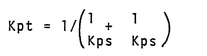
- The pattern stiffness in the case of no subg- rooves (Kpo) is to use h = ho in the
equation 1; and Circumferential stiffness index of the pattern
- The ratio of the volume of groove to total volume of shoulder part.

- By way of example consider four tyres made for trial. The first tyre provided has a width of pattern and carcass line profile (PV) according to this invention as shown in Fig.5 and a second tyre has a pattern of this invention and carcass line profile (PR) according to the prior art (Example 1 and Control Example 1, respectively) A third tyre with a pattern of the prior art as shown in Fig. 13-(b), a carcass line profile (PV) of this invention and a fourth tyre with the pattern of the prior art and the carcass line profile (PR) of the prior art (Control Example 2 and 3, respectively). Various kinds of tests such as tread surface strain, tread cutting resistance to rolling, comeeing force, and comfort in vehicle ride, suitability to high speed running, tread wear, and wet grip performance were performed.
- Specifications of the test samples are listed in Table 4.

- In the tyres, the
carcass 1 was composed of one ply of twisted steel cords (7 x 4/0.175mm) disposed at an angle of 90° with respect to the equatorial plane of the tyre and thebelt structure 3 was composed of twisted steel cords (1 x 3/0.20 + 6/0.38 mm). The first belt was disposed at 67° with respect to the equatorial plane of the tyre whereas the second through fourth belts was at 16°. - The belt adjacent to the carcass layer is referred to as the first belt, and succeeding ones as the second, third, and fourth in turn. Component materials belts such as tread rubber and others were common to all belts.

- The tyre of this example was found to be excellent in resistance to cut when knowing that compressive strain acts therein.
- Comfort and stability test were then carried out and the results of the investigations of the vertical spring rate as a scale for evaluating comfort in vehicle ride and stability in driving and about the relation between cornering force and tread surface strain were provided. The results are shown in Fig.7 and 8 and the tyre of Examples 1 of th is invention in which compressive strain acts is nor different in degree of deflection from Control Example 1 in Example 1 in which tensile strain acts but approximately 10% higher in intensity of cornering force. This data shows that high tension of the carcass ply acting on the portion extending from buttress to tread part and compressive strain acting in the direction of the tyre axis provide higher transverse stiffness at the ground contacting surface.
- From the above described facts, it can be said that comfort in vehicle ride provided by a tyre having a profile according to this invention is not different, as wil be referred to later again, from that by the conventional tyre but there is great superiority in respect of the stability in driving.
- To find the effect of the carcass profile, the intensity of reactive force generated in the rotational axes of tyres of Control Example 1 and Example 1 during running over protrusions in the test course and data as shown in table 3 for comparing two examples with respect to confor- tableness in riding during joint were obtained.
- Table 3 shows the results of the measurements of the reactive force in Example 1 in terms of an index based on the assumption that the index of the reactive force in Control Example 1 is 100, wherein the larger the index, the better the comfort of vehicle ride.

- From Table 3, the tyre of Example 1 was found to be superior to the conventional one providing improved comfort in vehicle ride. The reason for the above fact is that a great deal of flexional deformation inflicted on the tyre when the tyre rides over protrusions on the ground is absorbed in the sidewall parts of the tyre. In the tyre according to the invention, tension in the carcass ply is low in areas extending from positions, at which deformation absorption capacity reaches the maximum and between which the largest width of the tyre lies, to the bead parts on the sidewall portions lower than the above mentioned points, whereby tension distribution in these areas are capable of absorbing flexional deformation comparatively easily.
- Comparison of the rolling resistance of the tyre of Example 1 according to this invention with that of Control Example 1 of the prior art, as shown in Fig. 9, indicated that the former is 10% or more below the latter and, proportionately, contributes to a reduction in fuel consumption. The reason is that the movement of rubber in the tyre of this invention occurring every revolution of the tyre is smaller than that of the conventional tyre in the areas extending from the ground contacting surface to the buttress parts and energy loss in the tyre is reduced. The same remark as above is applicable to heat generation in the tyre, too.
- Rolling resistance is evaluated by the resistance of a tyre during running after the tyre is pressed to the surface of a steel drum of 1.7 m in diameter loaded as specified, after being driven for warming up for about 45 minutes at a speed and with internal pressure as specified.
- In view of improved road conditions of these days, importance must be attached to durability in high speed running of a tyre of such kind as above and to test durability in high speed running the following test was performed and the results thereof being shown in Table 5.

- Tyres were driven on the drum type driving tester according to the stepped speed running method on conditions that:
- Load : 3,780 kg
- Initial internal pressure : 7.25 kg/cm2
- Rim : 7.50 V
- As regards resistance of the tread to wear, comparison tests using a truck were performed and the amounts of wear of treads per 1,000 km running were compared by measurements of groove depths after 50,000 km running. As shown in Table 6, the tyre according to this invention demonstrated excellent resistance to wear thanks to low heat generation, more uniform distribution of ground contact pressure and high grip performance.

- Values obtained from comparison of wet grip performance are shown in Table 7.
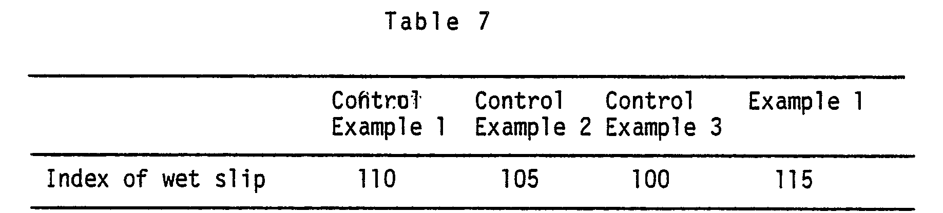
- Wet grip performance were observed by comparing the braking distance travelled by the truck driven initially at a speed of 80 km/h on an asphalt- paved wet road, and indicated in terms of an index on the assumption that the index of braking distance of Control Example 3 is 100. In this case, too, the larger the index, the better the performance, and a tyre of example 1 which exhibited a strong braking force is verified to be excellent in wet grip performance which is one important requirements for safety.
- In summary, as has been described, this invention provides a well-balanced tyre in which the radially expansive surface profile is expanded radially outwardly at both shoulder parts when the tyre is inflated and the tread pattern circumferential stiffness as well as the index of groove volume is optimised so that resitance to wear, durability in high speed running (low degree of heat generation), resitance to cutting and rolling resistance (low fuel consumption) including wet grip performance and stability in vehicle driving may be advantageously improved without reducing comfort in vehicle ride when subjected to jolting.
wherein results were evaluated by the level of speed at which the tyre failed due to heat generation and the length of time spent running at the above speed. A tyre of Example 1 of this invention cleared a speed of 130 km/h but a tyre of Control Example 1 could clear only 120 km/h, lower by one order than 130 km/h. Control Example 3 having conventional pattern plus conventional carcass ply showed a lower level of durability (100 km/h). Control Example 2 showed a level of 110 km/h because of the influence of the pattern. The tyre of this invention designed to be provided with "cut grooves" in the shoulder zones for reducing pattern circumferential stiffness and to cause compressive strain to act upon the tread rubber when the tyre is inflated reduced the amount of movement of the rubber and this controlled the heat generation in the shoulder parts, and provided a "high degree of durability".
Claims (8)
Applications Claiming Priority (2)
| Application Number | Priority Date | Filing Date | Title |
|---|---|---|---|
| JP60089514A JPS649002A (en) | 1985-04-24 | 1985-04-24 | High performance (low profile radial) tire |
| JP89514/85 | 1985-04-24 |
Publications (3)
| Publication Number | Publication Date |
|---|---|
| EP0202788A2 true EP0202788A2 (en) | 1986-11-26 |
| EP0202788A3 EP0202788A3 (en) | 1988-07-06 |
| EP0202788B1 EP0202788B1 (en) | 1991-03-20 |
Family
ID=13972894
Family Applications (1)
| Application Number | Title | Priority Date | Filing Date |
|---|---|---|---|
| EP86303082A Expired - Lifetime EP0202788B1 (en) | 1985-04-24 | 1986-04-24 | Tyre |
Country Status (6)
| Country | Link |
|---|---|
| US (1) | US4785861A (en) |
| EP (1) | EP0202788B1 (en) |
| JP (1) | JPS649002A (en) |
| AU (1) | AU592337B2 (en) |
| CA (1) | CA1266421A (en) |
| DE (1) | DE3678199D1 (en) |
Cited By (4)
| Publication number | Priority date | Publication date | Assignee | Title |
|---|---|---|---|---|
| EP0295898A1 (en) * | 1987-06-17 | 1988-12-21 | Sumitomo Rubber Industries Limited | Radial tyre for passenger cars |
| EP0339872A3 (en) * | 1988-04-22 | 1990-06-27 | Sumitomo Rubber Industries Limited | Pneumatic tyre |
| US8225834B2 (en) | 2008-03-11 | 2012-07-24 | The Yokohama Rubber Co., Ltd. | Pneumatic tire for heavy load |
| CN108025601A (en) * | 2015-10-06 | 2018-05-11 | 横滨橡胶株式会社 | Pneumatic tire |
Families Citing this family (24)
| Publication number | Priority date | Publication date | Assignee | Title |
|---|---|---|---|---|
| JPH0775922B2 (en) * | 1985-03-01 | 1995-08-16 | 住友ゴム工業株式会社 | Radial tire |
| US5027876A (en) * | 1989-11-13 | 1991-07-02 | The Goodyear Tire & Rubber Company | Environmental tire |
| US5637162A (en) * | 1991-09-19 | 1997-06-10 | Michelin Recherche Et Technique S.A. | Tire structure for improved tread life |
| US5353856A (en) * | 1992-06-08 | 1994-10-11 | The Yokohama Rubber Company, Ltd. | Pneumatic radial tire |
| US5710718A (en) * | 1993-01-27 | 1998-01-20 | Bridgestone Corporation | Method of designing a pneumatic tire to achieve a best mode under given conditions |
| US5565047A (en) * | 1993-08-25 | 1996-10-15 | Sumitomo Rubber Industries, Ltd. | Pneumatic tire with specified carcass line for reduced road noise |
| US5660652A (en) * | 1995-07-14 | 1997-08-26 | The Goodyear Tire & Rubber Company | Truck tire and tread for steer axles |
| JP3227402B2 (en) * | 1997-03-07 | 2001-11-12 | 住友ゴム工業株式会社 | Motorcycle tire, method of manufacturing the same, and vulcanizing mold used for the manufacture |
| US6367526B1 (en) | 1997-10-30 | 2002-04-09 | The Goodyear Tire & Rubber Company | Radial pneumatic light truck or automobile tire |
| USD452463S1 (en) | 2001-03-01 | 2001-12-25 | The Goodyear Tire & Rubber Company | Tire tread |
| WO2004041555A1 (en) | 2002-11-01 | 2004-05-21 | Bridgestone/Firestone North American Tire, Llc | Method for designing tire noise pitch sequence |
| US20100018628A1 (en) * | 2005-12-20 | 2010-01-28 | The Goodyear Tire & Rubber Co. | Method of manufacturing a radial aircraft tire |
| US20070137744A1 (en) * | 2005-12-20 | 2007-06-21 | Kiyoshi Ueyoko | Radial aircraft tire and method of manufacture |
| CN102781686B (en) | 2010-01-27 | 2015-02-18 | 普利司通美国轮胎运营有限责任公司 | Tires with noise-reducing tread patterns |
| US8776854B2 (en) * | 2011-08-29 | 2014-07-15 | The Goodyear Tire & Rubber Company | Pneumatic tire with improved crown durability |
| JP5498466B2 (en) * | 2011-10-20 | 2014-05-21 | 住友ゴム工業株式会社 | Heavy duty tire |
| JP5952587B2 (en) * | 2012-02-23 | 2016-07-13 | 住友ゴム工業株式会社 | Pneumatic tire |
| JP6314370B2 (en) * | 2013-04-17 | 2018-04-25 | 横浜ゴム株式会社 | Pneumatic tire |
| US10336139B2 (en) * | 2014-02-27 | 2019-07-02 | Compagnie Generale Des Etablissements Michelin | Body ply shape for a tire |
| WO2016068908A1 (en) * | 2014-10-29 | 2016-05-06 | Compagnie Generale Des Etablissements Michelin | Optimal body ply shape for heavy truck tire including belt plies in crown portion |
| US20170246909A1 (en) * | 2014-10-29 | 2017-08-31 | Compagnie Generale Des Etablissements Michelin | Optimal body ply shape for a tire |
| JP6825327B2 (en) * | 2016-11-22 | 2021-02-03 | 住友ゴム工業株式会社 | Pneumatic tires |
| CN108859615B (en) * | 2018-07-26 | 2024-04-19 | 厦门正新橡胶工业有限公司 | Tread pattern structure of pneumatic tires for rocky terrain |
| CN113752752B (en) * | 2021-08-24 | 2023-01-10 | 安徽佳通乘用子午线轮胎有限公司 | Low rolling resistance type load-carrying all-steel tire |
Family Cites Families (17)
| Publication number | Priority date | Publication date | Assignee | Title |
|---|---|---|---|---|
| GB1263184A (en) * | 1968-03-13 | 1972-02-09 | Dunlop Holdings Ltd | Improvements relating to pneumatic tyres |
| JPS5424762B2 (en) * | 1974-09-18 | 1979-08-23 | ||
| JPS5243204A (en) * | 1975-10-02 | 1977-04-05 | Bridgestone Corp | Flat air radial tire for heavy vehicle |
| JPS5953465B2 (en) * | 1977-07-21 | 1984-12-25 | 株式会社 サタケ | Automatic hot air temperature control device for grain dryer |
| FR2499473A1 (en) * | 1981-02-12 | 1982-08-13 | Michelin & Cie | Aircraft tyre sub-tread reinforcement with extensible borders - to sustain local tensile stress and suppress dynamic delamination stresses at high speeds |
| JPS5861008A (en) * | 1981-10-01 | 1983-04-11 | Sumitomo Rubber Ind Ltd | Radial tire inflated by air for heavy vehicle |
| JPS58164405A (en) * | 1982-03-23 | 1983-09-29 | Sumitomo Rubber Ind Ltd | Radial tyre |
| JPS5918002A (en) * | 1982-07-21 | 1984-01-30 | Bridgestone Corp | Pneumatic tyre for heavy load |
| JPS59179408A (en) * | 1983-03-31 | 1984-10-12 | Yokohama Rubber Co Ltd:The | Pneumatic tire |
| JPH069921B2 (en) * | 1983-04-28 | 1994-02-09 | 住友ゴム工業株式会社 | Radial tires for high-speed running on heavy roads |
| US4545415A (en) * | 1983-09-26 | 1985-10-08 | The Goodyear Tire & Rubber Company | Pneumatic tire tread |
| JPS60143106A (en) * | 1983-12-29 | 1985-07-29 | Bridgestone Corp | Pneumatic radial tire for heavy load |
| US4546808A (en) * | 1984-01-06 | 1985-10-15 | The Goodyear Tire & Rubber Company | Pneumatic tire |
| JPH0775922B2 (en) * | 1985-03-01 | 1995-08-16 | 住友ゴム工業株式会社 | Radial tire |
| JPS61226306A (en) * | 1985-03-30 | 1986-10-08 | Sumitomo Rubber Ind Ltd | High performance tire |
| JPS61235206A (en) * | 1985-04-12 | 1986-10-20 | Sumitomo Rubber Ind Ltd | High performance tire |
| JPS61238503A (en) * | 1985-04-15 | 1986-10-23 | Sumitomo Rubber Ind Ltd | High performance tire |
-
1985
- 1985-04-24 JP JP60089514A patent/JPS649002A/en active Pending
-
1986
- 1986-04-23 AU AU56550/86A patent/AU592337B2/en not_active Ceased
- 1986-04-23 US US06/854,783 patent/US4785861A/en not_active Expired - Fee Related
- 1986-04-24 EP EP86303082A patent/EP0202788B1/en not_active Expired - Lifetime
- 1986-04-24 CA CA000507441A patent/CA1266421A/en not_active Expired - Fee Related
- 1986-04-24 DE DE8686303082T patent/DE3678199D1/en not_active Expired - Fee Related
Cited By (5)
| Publication number | Priority date | Publication date | Assignee | Title |
|---|---|---|---|---|
| EP0295898A1 (en) * | 1987-06-17 | 1988-12-21 | Sumitomo Rubber Industries Limited | Radial tyre for passenger cars |
| EP0339872A3 (en) * | 1988-04-22 | 1990-06-27 | Sumitomo Rubber Industries Limited | Pneumatic tyre |
| US8225834B2 (en) | 2008-03-11 | 2012-07-24 | The Yokohama Rubber Co., Ltd. | Pneumatic tire for heavy load |
| CN108025601A (en) * | 2015-10-06 | 2018-05-11 | 横滨橡胶株式会社 | Pneumatic tire |
| CN108025601B (en) * | 2015-10-06 | 2019-12-24 | 横滨橡胶株式会社 | Pneumatic tire |
Also Published As
| Publication number | Publication date |
|---|---|
| AU592337B2 (en) | 1990-01-11 |
| EP0202788B1 (en) | 1991-03-20 |
| AU5655086A (en) | 1986-10-30 |
| JPS649002A (en) | 1989-01-12 |
| DE3678199D1 (en) | 1991-04-25 |
| US4785861A (en) | 1988-11-22 |
| EP0202788A3 (en) | 1988-07-06 |
| CA1266421A (en) | 1990-03-06 |
Similar Documents
| Publication | Publication Date | Title |
|---|---|---|
| EP0202788B1 (en) | Tyre | |
| EP0205233B1 (en) | Pneumatic tyre | |
| US5198047A (en) | Winter type tire tread | |
| EP0508090B1 (en) | Pneumatic tire having a unique footprint | |
| EP2357095B1 (en) | Pneumatic tyre | |
| EP0103984B1 (en) | Pneumatic radial tire and mould of manufacturing the same | |
| US6439284B1 (en) | Tread for a pneumatic tire including aquachannel | |
| EP0194108B1 (en) | A pneumatic radial tyre having a new carcass profile | |
| ITMI970103A1 (en) | TIRE WITH LOW ROLLING RESISTANCE IN PARTICULAR FOR DRIVE WHEELS OF HEAVY VEHICLES | |
| US5211781A (en) | Tire tread for large motor vehicles | |
| US20070151643A1 (en) | Heavy-duty tire | |
| US20200307319A1 (en) | Low noise tire tread | |
| US4955416A (en) | Pneumatic radial tire carcass profile | |
| EP0197735B1 (en) | Pneumatic tyre | |
| US20200198406A1 (en) | Tread for a pneumatic tire | |
| JP3336052B2 (en) | Pneumatic radial tire for winter | |
| EP1021306B1 (en) | Tread for a pneumatic tire | |
| JP7518750B2 (en) | Pneumatic radial tires for passenger cars | |
| EP4440853B1 (en) | Pneumatic tires for vehicle wheels | |
| JP7719373B2 (en) | tire | |
| CA1296982C (en) | High performance tire | |
| CA1291015C (en) | Pneumatic radial tire having a new carcass profile | |
| JPS61238503A (en) | High performance tire | |
| JP2026037612A (en) | tire | |
| JP2026037613A (en) | tire |
Legal Events
| Date | Code | Title | Description |
|---|---|---|---|
| PUAI | Public reference made under article 153(3) epc to a published international application that has entered the european phase |
Free format text: ORIGINAL CODE: 0009012 |
|
| AK | Designated contracting states |
Kind code of ref document: A2 Designated state(s): DE FR GB |
|
| PUAL | Search report despatched |
Free format text: ORIGINAL CODE: 0009013 |
|
| AK | Designated contracting states |
Kind code of ref document: A3 Designated state(s): DE FR GB |
|
| 17P | Request for examination filed |
Effective date: 19881101 |
|
| 17Q | First examination report despatched |
Effective date: 19891215 |
|
| GRAA | (expected) grant |
Free format text: ORIGINAL CODE: 0009210 |
|
| AK | Designated contracting states |
Kind code of ref document: B1 Designated state(s): DE FR GB |
|
| ET | Fr: translation filed | ||
| REF | Corresponds to: |
Ref document number: 3678199 Country of ref document: DE Date of ref document: 19910425 |
|
| PLBE | No opposition filed within time limit |
Free format text: ORIGINAL CODE: 0009261 |
|
| STAA | Information on the status of an ep patent application or granted ep patent |
Free format text: STATUS: NO OPPOSITION FILED WITHIN TIME LIMIT |
|
| 26N | No opposition filed | ||
| PGFP | Annual fee paid to national office [announced via postgrant information from national office to epo] |
Ref country code: FR Payment date: 19990409 Year of fee payment: 14 |
|
| PGFP | Annual fee paid to national office [announced via postgrant information from national office to epo] |
Ref country code: GB Payment date: 19990428 Year of fee payment: 14 |
|
| PGFP | Annual fee paid to national office [announced via postgrant information from national office to epo] |
Ref country code: DE Payment date: 19990430 Year of fee payment: 14 |
|
| PG25 | Lapsed in a contracting state [announced via postgrant information from national office to epo] |
Ref country code: GB Free format text: LAPSE BECAUSE OF NON-PAYMENT OF DUE FEES Effective date: 20000424 |
|
| GBPC | Gb: european patent ceased through non-payment of renewal fee |
Effective date: 20000424 |
|
| PG25 | Lapsed in a contracting state [announced via postgrant information from national office to epo] |
Ref country code: FR Free format text: LAPSE BECAUSE OF NON-PAYMENT OF DUE FEES Effective date: 20001229 |
|
| PG25 | Lapsed in a contracting state [announced via postgrant information from national office to epo] |
Ref country code: DE Free format text: LAPSE BECAUSE OF NON-PAYMENT OF DUE FEES Effective date: 20010201 |
|
| REG | Reference to a national code |
Ref country code: FR Ref legal event code: ST |