EP0202769A2 - Pivot assemblies for umbrella ribs - Google Patents
Pivot assemblies for umbrella ribs Download PDFInfo
- Publication number
- EP0202769A2 EP0202769A2 EP86302863A EP86302863A EP0202769A2 EP 0202769 A2 EP0202769 A2 EP 0202769A2 EP 86302863 A EP86302863 A EP 86302863A EP 86302863 A EP86302863 A EP 86302863A EP 0202769 A2 EP0202769 A2 EP 0202769A2
- Authority
- EP
- European Patent Office
- Prior art keywords
- inner part
- flange portion
- ribs
- struts
- umbrella
- Prior art date
- Legal status (The legal status is an assumption and is not a legal conclusion. Google has not performed a legal analysis and makes no representation as to the accuracy of the status listed.)
- Granted
Links
- 230000000712 assembly Effects 0.000 title description 3
- 238000000429 assembly Methods 0.000 title description 3
- 210000002105 tongue Anatomy 0.000 abstract description 8
- 239000000463 material Substances 0.000 description 3
- 229920001169 thermoplastic Polymers 0.000 description 2
- 239000004416 thermosoftening plastic Substances 0.000 description 2
- 238000010276 construction Methods 0.000 description 1
Images
Classifications
-
- A—HUMAN NECESSITIES
- A45—HAND OR TRAVELLING ARTICLES
- A45B—WALKING STICKS; UMBRELLAS; LADIES' OR LIKE FANS
- A45B25/00—Details of umbrellas
- A45B25/10—Umbrella crowns
-
- A—HUMAN NECESSITIES
- A45—HAND OR TRAVELLING ARTICLES
- A45B—WALKING STICKS; UMBRELLAS; LADIES' OR LIKE FANS
- A45B25/00—Details of umbrellas
- A45B25/06—Umbrella runners
Definitions
- This invention relates to pivot assemblies for umbrella ribs or struts, such as at a notch or a runner.
- a notch or a runner member for an umbrella prefferably be provided with pairs of lugs forming radial slots between which flattened ends of ribs or struts locate, the flattened ends and the lugs being provided with holes through which a wire is threaded to form pivot portions for the ribs or struts, and the ends of the wire being twisted together to secure it in place.
- the object of the invention is to simplify the construction and fitting of the pivot assemblies including both a notch or runner and the ribs or struts.
- a pivot assembly for umbrella ribs or struts comprises a notch or runner formed in two parts consisting of an inner part having a bore for fitting closely on an umbrella shaft and an outward annular flange portion adjacent one end of a tubular body portion the other end of which is divided to form at least two tongues, and an outer part having a sleeve portion fitting close on the body portion of the inner part and having an outward annular flange portion engaging the flange portion of the inner part, one of the flange portions being provided with radial slits each of which leads to a cavity formed between the flange portions, together with ribs or struts each of which has a knob end adjacent a flattened portion for sliding in one of the radial slits with the knob end held captive in the cavity formed between the flange portions, there being an engagement between the tongues of the inner part and the sleeve portion of the outer part to prevent them being separated after fitting on an umbrella shaft.
- the knob ends of the ribs or struts held captive between the flange portions act as pivots for the ribs or struts, which are guided for swinging by the sliding fit of their flattened portions within the radial slits, from positions alongside the shaft to radial positions. Thus no separate pivot or pivots need be formed and fitted.
- a pivot assembly 1 for umbrella ribs or struts 2 comprises a notch ( Figure 1) or runner ( Figure 3) formed by inner and outer parts 3, 4, the inner part 3 having a bore 5 for fitting closely on an umbrella shaft 6 (indicated in broken lines) and an outward annular flange portion 7 adjacent one end of a tubular body portion 8 the other end of which is divided to form two tongues 9, and the outer part (4) having a sleeve portion 10 fitting closely on the body portion 8 of.the inner part 3 and having an outward annular flange portion 11 engaging the flange portion 7 of the inner part, one of the flange portions being provided with radial slits 12 each of which leads to a cavity 13 formed between the flange portions, together with the ribs or struts 2 each of which has a knob end 14 adjacent a flattened portion 15 for sliding in one of the radial slits 12 with the knob end held captive in the cavity 13 (see also Figures 2 and 4 in
- the knob ends 14 of the ribs or struts 2 held captive between the flange portions 7, 11 act as pivots for the ribs or struts, which are guided for swinging by their flattened portions 15 within the radial slits 12, from positions alongside the shaft 6 (as shown at the right of Figures 1 and 3) to radial positions (as shown at the left in those Figures).
- the radial slits 12 are formed in the flange portion 11 of the outer part 4 and individual cavities 13 for the knob ends 14 are formed by radiating pairs of webs 16 (see Figure 2) across an annular recess 17 in that flange portion.
- the flange portion 7 of the inner part 3 has a generally U-shaped radial cross-section (minimising material whilst maximising strength) with the base 18 of the U effectively closing the cavities 13 in the flange portion of the outer part, and the outer limb 19 of the U is turned back outwards to form a rebate for location of a rim 20 of the flange portion 11 of the outer part 4.
- the radial slits 12 are formed in the flange portion 7 of the inner part 3, and individual cavities 13 for the knob ends 14 are formed by radiating pairs of webs 21 (see Figure 4) across an annular recess 22 in that flange portion, the sleeve portion 10 of the outer part 4 has an extension 23 incorporating the usual catch (not shown) in a housing 24 at one side of the extension, and the flange portion 11 of the outer part has a generally U-shaped radial cross section (again minimising material whilst maximising strength) with radial webs 25 providing abutment for the knob ends 14.
- a narrower U 26 formed round the outside of the flange portion 11 of the outer part 4 forms a rebate for location of rim 27 of the flange portion 7 of the inner part 3.
- the engagement between the tongues 9 of the inner part 3 and the sleeve portion 10 of the outer part 4 has a snap action, which is shown provided by outward ribs or "barbs" 28 on the tongues being pushed past a portion 29 of reduced diameter inside the sleeve portion, to prevent the two parts 3, 4 being separated after assembly with the ribs or struts 2 and before fitting on the umbrella shaft.
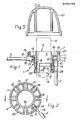
- the two parts 3, 4 of both notch and runner can be formed conveniently of thermoplastics, and a separate cap or "ornament" 30 (see Figure 5) be provided for the top of the umbrella shaft 6 and the notch after the latter has been secured to the shaft by a pin 31.
- the knob end 14 on each rib or strut 2 is conveniently formed by cropping the rod umbrella shaft (6).
Landscapes
- Walking Sticks, Umbrellas, And Fans (AREA)
- Vehicle Body Suspensions (AREA)
- Glass Compositions (AREA)
Abstract
Description
- This invention relates to pivot assemblies for umbrella ribs or struts, such as at a notch or a runner.
- It is known for a notch or a runner member for an umbrella to be provided with pairs of lugs forming radial slots between which flattened ends of ribs or struts locate, the flattened ends and the lugs being provided with holes through which a wire is threaded to form pivot portions for the ribs or struts, and the ends of the wire being twisted together to secure it in place.
- The object of the invention is to simplify the construction and fitting of the pivot assemblies including both a notch or runner and the ribs or struts.
- According to the present invention, a pivot assembly for umbrella ribs or struts comprises a notch or runner formed in two parts consisting of an inner part having a bore for fitting closely on an umbrella shaft and an outward annular flange portion adjacent one end of a tubular body portion the other end of which is divided to form at least two tongues, and an outer part having a sleeve portion fitting close on the body portion of the inner part and having an outward annular flange portion engaging the flange portion of the inner part, one of the flange portions being provided with radial slits each of which leads to a cavity formed between the flange portions, together with ribs or struts each of which has a knob end adjacent a flattened portion for sliding in one of the radial slits with the knob end held captive in the cavity formed between the flange portions, there being an engagement between the tongues of the inner part and the sleeve portion of the outer part to prevent them being separated after fitting on an umbrella shaft.
- The knob ends of the ribs or struts held captive between the flange portions act as pivots for the ribs or struts, which are guided for swinging by the sliding fit of their flattened portions within the radial slits, from positions alongside the shaft to radial positions. Thus no separate pivot or pivots need be formed and fitted.
- Preferred embodiments of the invention will now be described, by way of example only, with reference to the accompanying drawings, in which:-
- Figure 1 is an axial section through a notch for an umbrella and in accordance with the invention, the section being taken from the line I-I of Figure 2;
- Figure 2 is a plan view of the outer part of the notch shown in axial section in Figure 1;
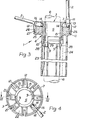
- Figure 3 is an axial section through a runner for an umbrella and in accordance with the invention, the section being taken from the line III-III of Figure 4;
- Figure 4 is an underneath plan view of the inner part of the runner shown in the axial section in Figure 3; and
- Figure 5 is a cap or "ornament" for the top of the umbrella shaft and the notch.
- In Figures 1 and 3 a pivot assembly 1 for umbrella ribs or
struts 2 comprises a notch (Figure 1) or runner (Figure 3) formed by inner andouter parts 3, 4, theinner part 3 having abore 5 for fitting closely on an umbrella shaft 6 (indicated in broken lines) and an outwardannular flange portion 7 adjacent one end of atubular body portion 8 the other end of which is divided to form twotongues 9, and the outer part (4) having asleeve portion 10 fitting closely on thebody portion 8 of.theinner part 3 and having an outwardannular flange portion 11 engaging theflange portion 7 of the inner part, one of the flange portions being provided withradial slits 12 each of which leads to acavity 13 formed between the flange portions, together with the ribs orstruts 2 each of which has aknob end 14 adjacent aflattened portion 15 for sliding in one of theradial slits 12 with the knob end held captive in the cavity 13 (see also Figures 2 and 4 in which only one rib orstrut 2 is shown for simplicity), there being an engagement between thetongues 9 of the inner part and thesleeve portion 10 of the outer part to prevent them being separated after fitting on to the umbrella shaft 6. - The knob ends 14 of the ribs or
struts 2 held captive between theflange portions flattened portions 15 within theradial slits 12, from positions alongside the shaft 6 (as shown at the right of Figures 1 and 3) to radial positions (as shown at the left in those Figures). - In the notch (Figure 1) the
radial slits 12 are formed in theflange portion 11 of the outer part 4 andindividual cavities 13 for theknob ends 14 are formed by radiating pairs of webs 16 (see Figure 2) across anannular recess 17 in that flange portion. Theflange portion 7 of theinner part 3 has a generally U-shaped radial cross-section (minimising material whilst maximising strength) with thebase 18 of the U effectively closing thecavities 13 in the flange portion of the outer part, and the outer limb 19 of the U is turned back outwards to form a rebate for location of arim 20 of theflange portion 11 of the outer part 4. - In the runner (Figure 3) the
radial slits 12 are formed in theflange portion 7 of theinner part 3, andindividual cavities 13 for theknob ends 14 are formed by radiating pairs of webs 21 (see Figure 4) across anannular recess 22 in that flange portion, thesleeve portion 10 of the outer part 4 has anextension 23 incorporating the usual catch (not shown) in ahousing 24 at one side of the extension, and theflange portion 11 of the outer part has a generally U-shaped radial cross section (again minimising material whilst maximising strength) withradial webs 25 providing abutment for theknob ends 14. A narrower U 26 formed round the outside of theflange portion 11 of the outer part 4 forms a rebate for location ofrim 27 of theflange portion 7 of theinner part 3. - The engagement between the
tongues 9 of theinner part 3 and thesleeve portion 10 of the outer part 4 has a snap action, which is shown provided by outward ribs or "barbs" 28 on the tongues being pushed past aportion 29 of reduced diameter inside the sleeve portion, to prevent the twoparts 3, 4 being separated after assembly with the ribs orstruts 2 and before fitting on the umbrella shaft. Thus the twoparts 3, 4 of both notch and runner can be formed conveniently of thermoplastics, and a separate cap or "ornament" 30 (see Figure 5) be provided for the top of the umbrella shaft 6 and the notch after the latter has been secured to the shaft by a pin 31. - The
knob end 14 on each rib orstrut 2 is conveniently formed by cropping the rod umbrella shaft (6). - 8. A pivot assembly as in any one of Claims 1 to 7, characterised in that the two parts (3, 4) of the notch or runner are formed of thermoplastics.
- 9. A pivot assembly as in any one of Claims 1 to 8, characterised in that the knob end (14) on each rib or strut (2) is formed by cropping the rod material from which the ribs or struts are formed a short distance beyond the end of its flattened portion (15).
Claims (1)
Priority Applications (1)
| Application Number | Priority Date | Filing Date | Title |
|---|---|---|---|
| AT86302863T ATE48514T1 (en) | 1985-05-16 | 1986-04-17 | LINKAGE FOR UMBRELLA POLES. |
Applications Claiming Priority (2)
| Application Number | Priority Date | Filing Date | Title |
|---|---|---|---|
| GB8512404 | 1985-05-16 | ||
| GB08512404A GB2175202A (en) | 1985-05-16 | 1985-05-16 | Pivot assemblies for umbrella ribs &c |
Publications (3)
| Publication Number | Publication Date |
|---|---|
| EP0202769A2 true EP0202769A2 (en) | 1986-11-26 |
| EP0202769A3 EP0202769A3 (en) | 1987-08-05 |
| EP0202769B1 EP0202769B1 (en) | 1989-12-13 |
Family
ID=10579237
Family Applications (1)
| Application Number | Title | Priority Date | Filing Date |
|---|---|---|---|
| EP86302863A Expired EP0202769B1 (en) | 1985-05-16 | 1986-04-17 | Pivot assemblies for umbrella ribs |
Country Status (4)
| Country | Link |
|---|---|
| EP (1) | EP0202769B1 (en) |
| AT (1) | ATE48514T1 (en) |
| DE (1) | DE3667384D1 (en) |
| GB (1) | GB2175202A (en) |
Cited By (11)
| Publication number | Priority date | Publication date | Assignee | Title |
|---|---|---|---|---|
| NL1003927C2 (en) * | 1996-08-30 | 1998-03-04 | Maxx Worldwide | Hinge between rib and crown of parasols with a diameter of more than 2 meters. |
| FR2854035A1 (en) * | 2003-04-22 | 2004-10-29 | Yves Michel Emile Fremont | Umbrella/ parasol/sunshade ribs fixing device, has sliding loop with covers comprising notches to receive ends of ribs that are maintained by covers in notches of sliding loop |
| US9078497B2 (en) | 2013-03-06 | 2015-07-14 | Oliver Joen-An Ma | Quick connector hub for shade structure |
| US9192215B2 (en) | 2013-03-04 | 2015-11-24 | Oliver Joen-An Ma | Quick assembly methods and components for shade structures |
| US9433269B2 (en) | 2014-02-25 | 2016-09-06 | Oliver Joen-An Ma | Quick assembly methods and components for shade structures |
| US20190119946A1 (en) * | 2015-09-14 | 2019-04-25 | Oliver Joen-An Ma | Components for shade structures |
| US10631604B2 (en) | 2012-04-19 | 2020-04-28 | ZHUN-AN Ma | Umbrella quick frame assembly systems and methods |
| US10631603B2 (en) | 2015-09-14 | 2020-04-28 | Oliver Joen-An Ma | Quick assembly methods and components for shade structures |
| US10736390B2 (en) | 2016-12-07 | 2020-08-11 | ZHUN-AN Ma | Umbrella hub assembly |
| US10874182B2 (en) | 2016-10-25 | 2020-12-29 | ZHUN-AN Ma | Umbrella rib connector assemblies and methods |
| USD1119794S1 (en) | 2022-07-22 | 2026-03-24 | ZHUN-AN Ma | Combined umbrella crank housing and battery assembly |
Families Citing this family (7)
| Publication number | Priority date | Publication date | Assignee | Title |
|---|---|---|---|---|
| RU2286704C1 (en) * | 2005-02-22 | 2006-11-10 | Андрущенко Владимир Владимирович | Umbrella |
| EP3199053B1 (en) | 2016-01-27 | 2018-08-22 | Activa Leisure Inc. | Quick connector for weather protection |
| USD826543S1 (en) | 2016-12-21 | 2018-08-28 | ZHUN-AN Ma | Umbrella housing |
| USD814173S1 (en) | 2016-12-21 | 2018-04-03 | ZHUN-AN Ma | Umbrella runner grip |
| USD828995S1 (en) | 2016-12-21 | 2018-09-25 | ZHUN-AN Ma | Umbrella housing |
| USD813525S1 (en) | 2016-12-21 | 2018-03-27 | ZHUN-AN Ma | Umbrella runner grip |
| USD833137S1 (en) | 2017-09-27 | 2018-11-13 | ZHUN-AN Ma | Umbrella hub |
Family Cites Families (2)
| Publication number | Priority date | Publication date | Assignee | Title |
|---|---|---|---|---|
| US904349A (en) * | 1908-02-28 | 1908-11-17 | Walter E Moulton | Top-notch for umbrellas. |
| IT1009845B (en) * | 1974-04-12 | 1976-12-20 | Redaelli Giuseppe & Fllo Spa | UPGRADE TO UMBRELLAS |
-
1985
- 1985-05-16 GB GB08512404A patent/GB2175202A/en not_active Withdrawn
-
1986
- 1986-04-17 EP EP86302863A patent/EP0202769B1/en not_active Expired
- 1986-04-17 DE DE8686302863T patent/DE3667384D1/en not_active Expired - Fee Related
- 1986-04-17 AT AT86302863T patent/ATE48514T1/en not_active IP Right Cessation
Cited By (15)
| Publication number | Priority date | Publication date | Assignee | Title |
|---|---|---|---|---|
| WO1998008412A1 (en) * | 1996-08-30 | 1998-03-05 | Maxx Worldwide | Hinge between bone and crown of sunshades with a diameter larger than 2 meters |
| NL1003927C2 (en) * | 1996-08-30 | 1998-03-04 | Maxx Worldwide | Hinge between rib and crown of parasols with a diameter of more than 2 meters. |
| FR2854035A1 (en) * | 2003-04-22 | 2004-10-29 | Yves Michel Emile Fremont | Umbrella/ parasol/sunshade ribs fixing device, has sliding loop with covers comprising notches to receive ends of ribs that are maintained by covers in notches of sliding loop |
| US10631604B2 (en) | 2012-04-19 | 2020-04-28 | ZHUN-AN Ma | Umbrella quick frame assembly systems and methods |
| US9192215B2 (en) | 2013-03-04 | 2015-11-24 | Oliver Joen-An Ma | Quick assembly methods and components for shade structures |
| US9078497B2 (en) | 2013-03-06 | 2015-07-14 | Oliver Joen-An Ma | Quick connector hub for shade structure |
| US9433269B2 (en) | 2014-02-25 | 2016-09-06 | Oliver Joen-An Ma | Quick assembly methods and components for shade structures |
| US20190119946A1 (en) * | 2015-09-14 | 2019-04-25 | Oliver Joen-An Ma | Components for shade structures |
| US10631605B2 (en) | 2015-09-14 | 2020-04-28 | Oliver Joen-An Ma | Umbrella hub |
| US10631603B2 (en) | 2015-09-14 | 2020-04-28 | Oliver Joen-An Ma | Quick assembly methods and components for shade structures |
| US11206904B2 (en) | 2015-09-14 | 2021-12-28 | Oliver Joen-An Ma | Quick assembly methods and components for shade structures |
| US10874182B2 (en) | 2016-10-25 | 2020-12-29 | ZHUN-AN Ma | Umbrella rib connector assemblies and methods |
| US10736390B2 (en) | 2016-12-07 | 2020-08-11 | ZHUN-AN Ma | Umbrella hub assembly |
| US11206905B2 (en) | 2016-12-07 | 2021-12-28 | ZHUN-AN Ma | Umbrella hub assembly |
| USD1119794S1 (en) | 2022-07-22 | 2026-03-24 | ZHUN-AN Ma | Combined umbrella crank housing and battery assembly |
Also Published As
| Publication number | Publication date |
|---|---|
| GB8512404D0 (en) | 1985-06-19 |
| EP0202769B1 (en) | 1989-12-13 |
| DE3667384D1 (en) | 1990-01-18 |
| GB2175202A (en) | 1986-11-26 |
| ATE48514T1 (en) | 1989-12-15 |
| EP0202769A3 (en) | 1987-08-05 |
Similar Documents
| Publication | Publication Date | Title |
|---|---|---|
| EP0202769A2 (en) | Pivot assemblies for umbrella ribs | |
| US5603532A (en) | Grab rings | |
| US4569211A (en) | Finger ring and insert therefor | |
| KR920005751A (en) | Magnetic Occlusion Blind Rivets | |
| US4457188A (en) | Shift lever mounting assembly | |
| CA2028627A1 (en) | Filter device | |
| KR850007035A (en) | Insertion tool for tangless coil inserts | |
| KR880004192A (en) | Latch for Automobile Door | |
| US5316355A (en) | Integral door knob assembly with spring return | |
| ES8708090A1 (en) | Hermetic terminal assembly. | |
| ES2009051A6 (en) | Chip-type micro-fuse | |
| US4608882A (en) | Knob with decorative end cap | |
| US4237575A (en) | Paint roller | |
| US5103528A (en) | Refrigeration, foam sealing bushing | |
| KR880000709A (en) | Bearing assembly | |
| US4352965A (en) | Toggle switch assembly | |
| KR850008216A (en) | Pole body for electric fuse and manufacturing method thereof | |
| DE3661591D1 (en) | Medical syringe | |
| KR910009054Y1 (en) | Fishing guide | |
| CA1073949A (en) | Cartridge type fuse | |
| JPS6217624Y2 (en) | ||
| KR860003672Y1 (en) | Knob of push button | |
| JP2540884Y2 (en) | Cut-out fixed electrode with built-in current limiting fuse | |
| JPS62117623U (en) | ||
| KR0137487Y1 (en) | Assembly structure of protector and balance spring |
Legal Events
| Date | Code | Title | Description |
|---|---|---|---|
| PUAI | Public reference made under article 153(3) epc to a published international application that has entered the european phase |
Free format text: ORIGINAL CODE: 0009012 |
|
| AK | Designated contracting states |
Kind code of ref document: A2 Designated state(s): AT BE CH DE FR GB IT LI LU NL SE |
|
| PUAL | Search report despatched |
Free format text: ORIGINAL CODE: 0009013 |
|
| AK | Designated contracting states |
Kind code of ref document: A3 Designated state(s): AT BE CH DE FR GB IT LI LU NL SE |
|
| 17P | Request for examination filed |
Effective date: 19870923 |
|
| 17Q | First examination report despatched |
Effective date: 19880907 |
|
| GRAA | (expected) grant |
Free format text: ORIGINAL CODE: 0009210 |
|
| AK | Designated contracting states |
Kind code of ref document: B1 Designated state(s): AT BE CH DE FR GB IT LI LU NL SE |
|
| PG25 | Lapsed in a contracting state [announced via postgrant information from national office to epo] |
Ref country code: SE Effective date: 19891213 Ref country code: NL Effective date: 19891213 Ref country code: LI Effective date: 19891213 Ref country code: CH Effective date: 19891213 Ref country code: BE Effective date: 19891213 Ref country code: AT Effective date: 19891213 |
|
| REF | Corresponds to: |
Ref document number: 48514 Country of ref document: AT Date of ref document: 19891215 Kind code of ref document: T |
|
| REF | Corresponds to: |
Ref document number: 3667384 Country of ref document: DE Date of ref document: 19900118 |
|
| ITF | It: translation for a ep patent filed | ||
| RAP4 | Party data changed (patent owner data changed or rights of a patent transferred) |
Owner name: HOYLAND FOX LIMITED |
|
| RAP2 | Party data changed (patent owner data changed or rights of a patent transferred) |
Owner name: HOYLAND FOX LIMITED |
|
| REG | Reference to a national code |
Ref country code: CH Ref legal event code: PFA Free format text: HOYLAND FOX LIMITED |
|
| ET | Fr: translation filed | ||
| REG | Reference to a national code |
Ref country code: CH Ref legal event code: PL |
|
| PG25 | Lapsed in a contracting state [announced via postgrant information from national office to epo] |
Ref country code: LU Free format text: LAPSE BECAUSE OF NON-PAYMENT OF DUE FEES Effective date: 19900430 |
|
| NLV1 | Nl: lapsed or annulled due to failure to fulfill the requirements of art. 29p and 29m of the patents act | ||
| PLBE | No opposition filed within time limit |
Free format text: ORIGINAL CODE: 0009261 |
|
| STAA | Information on the status of an ep patent application or granted ep patent |
Free format text: STATUS: NO OPPOSITION FILED WITHIN TIME LIMIT |
|
| 26N | No opposition filed | ||
| ITTA | It: last paid annual fee | ||
| PGFP | Annual fee paid to national office [announced via postgrant information from national office to epo] |
Ref country code: GB Payment date: 19980331 Year of fee payment: 13 |
|
| PGFP | Annual fee paid to national office [announced via postgrant information from national office to epo] |
Ref country code: FR Payment date: 19980415 Year of fee payment: 13 |
|
| PGFP | Annual fee paid to national office [announced via postgrant information from national office to epo] |
Ref country code: DE Payment date: 19980428 Year of fee payment: 13 |
|
| PG25 | Lapsed in a contracting state [announced via postgrant information from national office to epo] |
Ref country code: GB Free format text: LAPSE BECAUSE OF NON-PAYMENT OF DUE FEES Effective date: 19990417 |
|
| GBPC | Gb: european patent ceased through non-payment of renewal fee |
Effective date: 19990417 |
|
| PG25 | Lapsed in a contracting state [announced via postgrant information from national office to epo] |
Ref country code: FR Free format text: LAPSE BECAUSE OF NON-PAYMENT OF DUE FEES Effective date: 19991231 |
|
| REG | Reference to a national code |
Ref country code: FR Ref legal event code: ST |
|
| PG25 | Lapsed in a contracting state [announced via postgrant information from national office to epo] |
Ref country code: DE Free format text: LAPSE BECAUSE OF NON-PAYMENT OF DUE FEES Effective date: 20000201 |
|
| PG25 | Lapsed in a contracting state [announced via postgrant information from national office to epo] |
Ref country code: IT Free format text: LAPSE BECAUSE OF NON-PAYMENT OF DUE FEES;WARNING: LAPSES OF ITALIAN PATENTS WITH EFFECTIVE DATE BEFORE 2007 MAY HAVE OCCURRED AT ANY TIME BEFORE 2007. THE CORRECT EFFECTIVE DATE MAY BE DIFFERENT FROM THE ONE RECORDED. Effective date: 20050417 |