EP0202764A2 - Potentiometer - Google Patents
Potentiometer Download PDFInfo
- Publication number
- EP0202764A2 EP0202764A2 EP86302820A EP86302820A EP0202764A2 EP 0202764 A2 EP0202764 A2 EP 0202764A2 EP 86302820 A EP86302820 A EP 86302820A EP 86302820 A EP86302820 A EP 86302820A EP 0202764 A2 EP0202764 A2 EP 0202764A2
- Authority
- EP
- European Patent Office
- Prior art keywords
- track
- wiper
- network
- resistance
- potentiometer
- Prior art date
- Legal status (The legal status is an assumption and is not a legal conclusion. Google has not performed a legal analysis and makes no representation as to the accuracy of the status listed.)
- Withdrawn
Links
- 239000000758 substrate Substances 0.000 claims abstract description 8
- 239000004020 conductor Substances 0.000 claims description 16
- 238000006073 displacement reaction Methods 0.000 claims description 12
- 238000007639 printing Methods 0.000 claims description 9
- 239000000463 material Substances 0.000 claims description 5
- 229920001940 conductive polymer Polymers 0.000 claims description 4
- 238000005520 cutting process Methods 0.000 claims description 4
- 238000007650 screen-printing Methods 0.000 claims description 4
- 230000008859 change Effects 0.000 claims description 3
- 230000000694 effects Effects 0.000 claims description 3
- 239000003973 paint Substances 0.000 claims description 3
- 238000013459 approach Methods 0.000 claims description 2
- 238000000034 method Methods 0.000 description 5
- 238000004519 manufacturing process Methods 0.000 description 4
- 230000020347 spindle assembly Effects 0.000 description 3
- 238000005299 abrasion Methods 0.000 description 2
- 238000001514 detection method Methods 0.000 description 2
- 230000007480 spreading Effects 0.000 description 2
- 238000003892 spreading Methods 0.000 description 2
- 230000008901 benefit Effects 0.000 description 1
- 230000015572 biosynthetic process Effects 0.000 description 1
- 230000008021 deposition Effects 0.000 description 1
- 239000012777 electrically insulating material Substances 0.000 description 1
- 230000007246 mechanism Effects 0.000 description 1
- 239000002861 polymer material Substances 0.000 description 1
- 238000002360 preparation method Methods 0.000 description 1
- 238000009966 trimming Methods 0.000 description 1
Images

Classifications
-
- F—MECHANICAL ENGINEERING; LIGHTING; HEATING; WEAPONS; BLASTING
- F02—COMBUSTION ENGINES; HOT-GAS OR COMBUSTION-PRODUCT ENGINE PLANTS
- F02D—CONTROLLING COMBUSTION ENGINES
- F02D11/00—Arrangements for, or adaptations to, non-automatic engine control initiation means, e.g. operator initiated
- F02D11/06—Arrangements for, or adaptations to, non-automatic engine control initiation means, e.g. operator initiated characterised by non-mechanical control linkages, e.g. fluid control linkages or by control linkages with power drive or assistance
- F02D11/10—Arrangements for, or adaptations to, non-automatic engine control initiation means, e.g. operator initiated characterised by non-mechanical control linkages, e.g. fluid control linkages or by control linkages with power drive or assistance of the electric type
- F02D11/106—Detection of demand or actuation
-
- H—ELECTRICITY
- H01—ELECTRIC ELEMENTS
- H01C—RESISTORS
- H01C10/00—Adjustable resistors
- H01C10/30—Adjustable resistors the contact sliding along resistive element
- H01C10/305—Adjustable resistors the contact sliding along resistive element consisting of a thick film
-
- H—ELECTRICITY
- H01—ELECTRIC ELEMENTS
- H01C—RESISTORS
- H01C10/00—Adjustable resistors
- H01C10/30—Adjustable resistors the contact sliding along resistive element
- H01C10/32—Adjustable resistors the contact sliding along resistive element the contact moving in an arcuate path
- H01C10/36—Adjustable resistors the contact sliding along resistive element the contact moving in an arcuate path structurally combined with switching arrangements
-
- H—ELECTRICITY
- H01—ELECTRIC ELEMENTS
- H01C—RESISTORS
- H01C17/00—Apparatus or processes specially adapted for manufacturing resistors
- H01C17/22—Apparatus or processes specially adapted for manufacturing resistors adapted for trimming
- H01C17/23—Apparatus or processes specially adapted for manufacturing resistors adapted for trimming by opening or closing resistor geometric tracks of predetermined resistive values, e.g. snapistors
Definitions
- This invention relates to electical potentiometers of linear or rotary type and particularly to potentiometers for use with automotive engine management systems.
- Such potentiometers may, for example, find application as throttle position sensors.
- Electrical potentiometers are well known for use in microprocessor controlled engine management systems. They are applied, for example, for throttle position sensing where an output voltage, as a wiper traverses an arcuate resistance track, is proportional to the position of the wiper along the track and hence to the position of a throttle connected to the wiper by means of a rotatable spindle.
- potentiometers are designed to provide a voltage output which bears a particular relationship to the angle of rotation of the wiper/spindle assembly.
- the relationship between the output and the angle of rotation may be required to be linear and with a particular slope.
- the actual slope is often different from that which is intended.
- potentiometers involving screen-printed conductors and resistance tracks this may be due to eccentricity of the resistance track relative to the position of the wiper spindle as a result of printing errors.
- some potentiometers now require resistors to be provided connected between a source of applied voltage and the ends of the wiped resistance track in the potentiometer in order to ensure that the output voltage from the potentiometer can never reach the level of the applied voltage.
- the resistors provided at the ends of the track are normally required to have a resistance value which represents a very small proportion (e.g. 1%) of the resistance value of the track. It would be convenient to provide these resistors in film form inside the potentiometer by screen printing using the same resistance material as the resistance track, but it would be extremely difficult to print resistors of the necessarily small dimensions to achieve the low resistance value to the required accuracy. Unless expensive adjustment techniques, such as those involving lasers, are employed, trimming of the very small resistors to value would be very difficult to carry out, to achieve the required precision.
- the present invention provides an electrical potentiometer comprising:
- Fine adjustment of the resistance value of the said network may be effected by removing a portion of one or more said resistance elements.
- the single film resistive element may be in the form of an elongate strip that registers with first and second sets of inter-digitated conductive fingers traversing the strip from opposed sides, portions of the strip between adjoining fingers defining the resistors of the network, the fingers of each set being initially interconnected and the fingers of one set being connected to a conductive termination of the track.
- said single film resistance element is integral with said track, or has been formed simultaneously with said track.
- the said resistance elements in said network are connected initially in parallel by said film links.
- a further said film electrical resistor network may be provided on said substrate at a second end of said track in series with said track and said second terminal, or in parallel with a portion of said track at said second end of said track.
- said track, said terminals and the or each said resistor network are provided by screen printing.
- a single printing operation may be employed to produce the said track and the said single film resistance element used in said network.
- Another single printing operation may be employed to provide said terminals and the said conductive film links.
- said track, said terminals and said resistance network each comprise an electrically conductive polymer or paint material having required electrically conductive or resistive properties.
- a said resistor network is provided at said first end of said track in series with said track and said first terminal and a further said network is provided at said second end of said track in series with said track and said second terminal, said networks being adapted and arranged whereby said output voltage from the potentiometer is prevented from reaching a level of the applied voltage, thereby serving as a safety means in said potentiometer.
- a said resistor network is provided at said first end of said track in series with said track and said first terminal, and/or a said resistor network is provided at said second end of said track in series with said track and said second terminal, adjustment of the resistance value of the or each said network being effected to achieve a required slope for a linear relationship between said output voltage and displacement of said wiper along said track. If said network is provided at an end of said track which when approached by said wiper results in said output voltage approaching a maximum value, adjustment of the resistance of the network to increase the value thereof in series with said track may be effected to reduce, by a desired amount, the said slope for the said linear relationship.
- a said resistor network is provided at said first end or said second end of said track in series with said track and said first or said second terminal respectively, adjustment of resistance value of said network being effected to adjust to a predetermined level the said output voltage at a predetermined position of displacement of said wiper along said track.
- switch means may be incorporated in the potentiometer for controlling an associated circuit and arranged to operate at said predetermined position of displacement of said wiper.
- the switch means suitably includes an elongate electrically conductive film extending alongside, but separated from, said track and arranged to be traversed by a further wiper arranged in ganged relationship with the said wiper which traverses said resistance track and such that at the said predetermined position of displacement of said wiper, said further wiper passes from said conductive film onto an electrically insulating surface. Terminals for said switch are suitably provided electrically connected to said conductive film and said further wiper.
- a pad of electrically conductive material covering a portion of said track at a predetermined distance from an end of said track, a said resistor network being connected between said pad and a terminal for the potentiometer connected to said end of said track, such that as said wiper passes over said pad the output voltage from said potentiometer remains substantially constant at a level predetermined by means of the resistor network.
- the said network also operates such that as the wiper is caused to traverse the track in a particular direction, the rate of change of output voltage as the wiper approaches the pad is different compared with that after the wiper leaves the pad.
- the embodiment is particularly advantageous when the potentiometer is used in automotive sensor applications since the provision of the pad allows a degree of mechanical overtravel of the wiper in the potentiometer to be accommodated and excess overtravel to be determined for error detection or to initiate a safety program.
- the use of the said resistor network in the potentiometer of the invention enables the same resistance material to be readily used for the resistance track and for the elements in the network.
- the track and network thereby have the same temperature coefficient of resistance which is advantageous.
- the use of a resistor network incorporating elements connected initially in parallel allows dimensionally larger resistance elements to be used in the network compared with the dimensions which would be required for a single resistor of film form if substituted for the network.
- the said elongate resistance track mav be of arcuate or rectilinear form.
- an electrical potentiometer is constructed as follows.
- An electrically conductive wiper 3 is supported on a carrier 4 and arranged to traverse the resistance track 1, the carrier 4 being secured to a rotatable spindle 5 which is adapted to be mechanically connected to be rotated by an external device (not shown), such as a throttle mechanism in an automobile engine.
- the wiper 3 is electrically connected to a terminal 6 by way of a further wiper 7 and a conductive collector 8.
- Film electrical resistor networks generally denoted by reference numerals 9A and 9B are provided at either end of the track 1.
- a detail of the network 9A is shown in Figure 2A.
- the networks 9A and 9B are arranged in series with the track 1 and electrically conductive terminals 10 and 11 respectively.
- the terminals 10 and 11 are arranged to be connected for application of a voltage source to the track 1.
- the networks 9A and 9B are formed by printing resistance elements 12A and 12B as extensions of the track 1 and suitably simultaneously with the deposition of the track 1.
- the single resistance elements 12A and 12B are each formed into a plurality of resistance elements 13A and l3B respectively, connected in parallel, by application of electrically conductive film links 14A and 14B.
- the links 14A and 14B are suitably provided in the form of a low temperature curable conductive polymer or paint material of suitably high conductivity, by screen printing and are provided simultaneously with the formation of the terminals 10 and 11.
- the conductive material of the links 14A and 14B also extends to form end conductors 15A and 15B for the track 1.
- the resistance value of the networks 9A and 9B, between terminal 10 and track end conductor 15A and between terminal 11 and track end conductor 15B respectively, is able to be adjusted as required, to connect a particular value of electrical resistance in series with the track 1.
- An example of the adjustment technique is given with reference to Figures 2A and 2B.
- the network 9A comprises four resistance elements 13A connected initially in parallel by means of the conductive links 14A. If each element has substantially the same resistance value R E then the initial resistance value R T of the network between terminal 10 and the end conductor 15A of the track 1 will be equal to R E/ 4. If a cut is made through one of the conductive links 14A at position Ci, the resistance R T of the network will increase to RE/3.
- the resistance R T of the network will be equal to R E / 2. If instead of cut C 1 , cuts are made at positions C 2 and C 3 , the resistance R T of the network will be equal to 0.75R E . If instead of cuts C l , C 2 and C 3 a cut is made at position C4 , the resistance R T will be equal to R E . Cutting through the film links at any of the positions C 1 to C4 can readily be achieved by well-known mechanical abrasion techniques. If the stepwise adjustment of the achieved with accuracy. If for example only resistor network 9B is incorporated in the potentiometer, i.e.
- a third advantage resulting from the use of one or both resistor networks 9A and/or 9B is the ability to provide precise adjustment of the output voltage at terminal 6 at a predetermined position of displacement of the wiper 3 along the track. This is particularly advantageous when a switch means is associated with the potentiometer and which is to be actuated at this predetermined position of displacement of the wiper along the track.
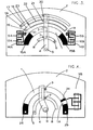
- Figure 3 illustrates an example of a potentiometer and switch arrangement of this nature.
- FIG 3 parts which are the same as those in the arrangement of Figure 1 have the same reference numerals as in Figure 1 and operate in the same manner as described with reference to Figure 1.
- the arrangement shown in Figure 3 is provided with a switch means constructed as follows.
- a pair of arcuate electrically conductive tracks 16 and 17 are provided alongside, and spaced from, the resistance track 1.
- Terminals 18 and 19 are provided on the conductive tracks 16 and 17 respectively, for connection to an external circuit (not shown) in which a switching function is required.
- Electrically conductive wipers 20 and 21, arranged to traverse the conductive tracks 16 and 17 respectively, are electrically connected together and supported on the same wiper carrier 4 as the wipers 3 and 7 which traverse the resistance track 1 and collector 8 respectively.
- the wipers 20 and 21 are therefore in gange3 operating relationship with the wipers 3 and 7.
- a film of electrically insulating material 22 is provided covering a proportion of the length of the conductive track 17 and such that a region of the conductive tract 17 remains resistance value R T of the network is too coarse to achieve a desired value of R T with sufficient accuracy, a fine trim can be effected by removing a small portion of one or more of the resistance elements 13A in known manner, e.g. by mechanical abrasion or cutting.
- resistor networks 9A and 9B a required resistance value can be introduced in series with track 1 and terminals 10 and 11 respectively.
- the resistor networks 9A and/or 9B can serve the following roles in a potentiometer. Firstly they can function as safety resistors to ensure that an output voltage at terminal 6 is prevented from ever reaching the level of the voltage applied to terminals 10 and 11. Such a safety feature is becoming increasingly important in the case of potentiometers employed in automobile engine management systems, e.g. for throttle position sensing. Secondly, one or both resistor networks 9A, 9B can be employed to provide a correction for the slope of a graphical linear relationship between the output voltage at terminal 6 and the displacement of wiper 3 along the track 1.
- This slope may, in practice, be different from that which was intended, on account of tolerances in the manufacturing processes of potentiometers., These may result in errors in the effective angle of wipe by the wiper 3 between conductors 15A, 15B at opposite ends of the track 1, particularly on account of spreading, during printing, of the conductive ink used for the end conductors. Printing errors may also result in eccentricity of the resistance track relative to the position of the wiper spindle 5.
- One or both resistor networks 9A and/or 9B can be used to compensate for this and effectively adjust the law output slope to precisely that which is required, the resistance adjustment facility on the networks allowing this to be exposed extending from the termination 19.
- This arrangement provides a switch for operating a circuit when connected to terminals 18 and 19.
- the output voltage at terminal 6 of the potentiometer may be at an accurately predetermined level when the wiper 21 traverses the interface 23 between the conductive track 17 and the insulating film 22, i.e. at the operating point of the switch.
- This output voltage level is able to be set with the required precision by adjustment of the resistance value of the resistor networks 9A and/or 9B by the method previously described with reference to Figures 1 and 2.
- This arrangement of potentiometer and switch finds particular application in automotive engine management systems.
- a pad 24 of electrically conductive material is provided covering a portion of the resistance track I near to and at a predetermined distance from an end of the track where a conductive terminal 25 is provided. It is arranged for a voltage source to be connected between terminal 25 and a further terminal 26 provided at the other end of the track 1.
- a resistor network 9B of the kind previously described is connected between the pad 24 and the terminal 25.
- the output voltage at terminal 6 remains substantially constant at a level predetermined by adjustment of the resistance value of the resistor network 9B.
- the wiper is caused to be traversed further and moves off the pad 24 onto region 1A of the track 1 the output voltage at terminal 6 increases again but the rate of change of voltage is now smaller than previously as a result of the effect of the network 9B.
- This embodiment is advantageous when the potentiometer is used in automotive applications, e.g. as a throttle position sensor.
- the wiper 3 would normally be arranged to operate between the terminal 26 and the pad 24.
- any mechanical overtravel in the system would cause the wiper to move further over the pad 24 without any increase in output voltage occurring, the dimensions of the pad 24 providing prescribed limits for the amount of overtravel which can be accommodated. If excess overtravel occurs such that the wiper 3 leaves the pad 24 and traverses the region 1A of the track 1 towards the terminal 25, the increasing output voltage at terminal 6 will cause an error detection or safety program to be executed in an associated electronic system.
- a network similar to network 9A in Figure 1 may be provided in addition to, or instead of, network 9B, but at the opposite end of track 1 and functioning in similar manner to network 9B.
Landscapes
- Engineering & Computer Science (AREA)
- Microelectronics & Electronic Packaging (AREA)
- Manufacturing & Machinery (AREA)
- Chemical & Material Sciences (AREA)
- Combustion & Propulsion (AREA)
- Mechanical Engineering (AREA)
- General Engineering & Computer Science (AREA)
- Adjustable Resistors (AREA)
- Transmission And Conversion Of Sensor Element Output (AREA)
Applications Claiming Priority (2)
| Application Number | Priority Date | Filing Date | Title |
|---|---|---|---|
| GB08509773A GB2173955B (en) | 1985-04-17 | 1985-04-17 | Potentiometer |
| GB8509773 | 1985-04-17 |
Publications (2)
| Publication Number | Publication Date |
|---|---|
| EP0202764A2 true EP0202764A2 (de) | 1986-11-26 |
| EP0202764A3 EP0202764A3 (de) | 1988-04-20 |
Family
ID=10577764
Family Applications (1)
| Application Number | Title | Priority Date | Filing Date |
|---|---|---|---|
| EP86302820A Withdrawn EP0202764A3 (de) | 1985-04-17 | 1986-04-16 | Potentiometer |
Country Status (2)
| Country | Link |
|---|---|
| EP (1) | EP0202764A3 (de) |
| GB (1) | GB2173955B (de) |
Cited By (4)
| Publication number | Priority date | Publication date | Assignee | Title |
|---|---|---|---|---|
| EP0322785A3 (en) * | 1987-12-29 | 1990-02-14 | Siemens Aktiengesellschaft | Pedal return arrangement |
| GB2233506A (en) * | 1989-06-21 | 1991-01-09 | Crystalate Electronics | Potentiometer |
| WO1992009995A1 (de) * | 1990-11-29 | 1992-06-11 | Robert Bosch Gmbh | Potentiometer zur bestimmung der position eines bewegbaren teils |
| EP1154442A3 (de) * | 2000-04-10 | 2005-01-05 | Sirona Dental Systems GmbH | Variabler Widerstand und damit versehener Spannungsteiler, Leiterplatte und zahnärztliches Gerät |
Families Citing this family (1)
| Publication number | Priority date | Publication date | Assignee | Title |
|---|---|---|---|---|
| EP1273889A1 (de) * | 2001-07-02 | 2003-01-08 | CTS Corporation | Drehwinkelsensor |
Family Cites Families (11)
| Publication number | Priority date | Publication date | Assignee | Title |
|---|---|---|---|---|
| US2724759A (en) * | 1954-03-04 | 1955-11-22 | Vari Ohm Corp | Precision wire wound resistors |
| FI52780C (fi) * | 1974-06-18 | 1977-11-10 | Paramic Ab Oy | Vastusarvoltaan aseteltava vastusverkko. |
| GB1500394A (en) * | 1976-04-27 | 1978-02-08 | Welwyn Electric Ltd | Electrical resistor network |
| US4172249A (en) * | 1977-07-11 | 1979-10-23 | Vishay Intertechnology, Inc. | Resistive electrical components |
| US4378549A (en) * | 1977-07-11 | 1983-03-29 | Vishay Intertechnology, Inc. | Resistive electrical components |
| US4134096A (en) * | 1977-11-10 | 1979-01-09 | Allen-Bradley Company | Trimmable resistor |
| DE2812928A1 (de) * | 1978-03-23 | 1979-10-04 | Agfa Gevaert Ag | Vorrichtung zum abgleichen von in elektrischen mess-, regel- oder steuerkreisen angeordneten abgleichwiderstaenden |
| US4201970A (en) * | 1978-08-07 | 1980-05-06 | Rca Corporation | Method and apparatus for trimming resistors |
| DE3013830A1 (de) * | 1979-10-20 | 1981-05-14 | Duk Man Seoul Moon | Verfahren zur herstellung eines flexiblen widerstandds-films fuer mehrfach-lautstaerkeregler sowie mit diesem verfahren hergestellter mehrfach-lautstaerkeregler |
| US4386460A (en) * | 1981-05-14 | 1983-06-07 | Bell Telephone Laboratories, Incorporated | Method of making multi-megohm thin film resistors |
| DE3405934A1 (de) * | 1984-02-18 | 1985-08-22 | Vdo Adolf Schindling Ag, 6000 Frankfurt | Potentiometerschaltung sowie verfahren zum abgleichen eines rueckmeldepotentiometers |
-
1985
- 1985-04-17 GB GB08509773A patent/GB2173955B/en not_active Expired
-
1986
- 1986-04-16 EP EP86302820A patent/EP0202764A3/de not_active Withdrawn
Cited By (4)
| Publication number | Priority date | Publication date | Assignee | Title |
|---|---|---|---|---|
| EP0322785A3 (en) * | 1987-12-29 | 1990-02-14 | Siemens Aktiengesellschaft | Pedal return arrangement |
| GB2233506A (en) * | 1989-06-21 | 1991-01-09 | Crystalate Electronics | Potentiometer |
| WO1992009995A1 (de) * | 1990-11-29 | 1992-06-11 | Robert Bosch Gmbh | Potentiometer zur bestimmung der position eines bewegbaren teils |
| EP1154442A3 (de) * | 2000-04-10 | 2005-01-05 | Sirona Dental Systems GmbH | Variabler Widerstand und damit versehener Spannungsteiler, Leiterplatte und zahnärztliches Gerät |
Also Published As
| Publication number | Publication date |
|---|---|
| EP0202764A3 (de) | 1988-04-20 |
| GB8509773D0 (en) | 1985-05-22 |
| GB2173955A (en) | 1986-10-22 |
| GB2173955B (en) | 1988-12-21 |
Similar Documents
| Publication | Publication Date | Title |
|---|---|---|
| US4435691A (en) | Dual track resistor element having nonlinear output | |
| US5051719A (en) | Thick-film non-step resistor with accurate resistance characteristic | |
| US4243969A (en) | Layer resistor element | |
| US4123741A (en) | Resistance element for variable resistors | |
| US4403133A (en) | Method of trimming a resistance element | |
| EP0202764A2 (de) | Potentiometer | |
| US4528546A (en) | High power thick film | |
| US4352005A (en) | Trimming a circuit element layer of an electrical circuit assembly | |
| US4751492A (en) | Variable resistor | |
| GB2048495A (en) | Liquid level sensor | |
| US4983946A (en) | Variable resistor with switching mechanism | |
| GB2122033A (en) | Rotary potentiometer | |
| US5148143A (en) | Precision thick film elements | |
| US6639508B1 (en) | Electrical switch device and process for manufacturing same | |
| CA1116311A (en) | Method for forming universal film resistors | |
| US4841275A (en) | Thick-film integrated circuit device capable of being manufactured by means of easy-to-perform trimming operation | |
| US4769626A (en) | Positive feel variable resistance switch | |
| JPH08186011A (ja) | 電流検知抵抗器及びその調整方法 | |
| US3665365A (en) | Multi-impedance electrical component | |
| US4771263A (en) | Variable resistance switch | |
| US5243318A (en) | Low noise precision resistor | |
| US4365230A (en) | Lead screw type variable resistor | |
| US4728921A (en) | Position indicator for an actuating drive | |
| US4039994A (en) | Variable output function potentiometer | |
| US4041439A (en) | Potentiometers |
Legal Events
| Date | Code | Title | Description |
|---|---|---|---|
| PUAI | Public reference made under article 153(3) epc to a published international application that has entered the european phase |
Free format text: ORIGINAL CODE: 0009012 |
|
| AK | Designated contracting states |
Kind code of ref document: A2 Designated state(s): BE DE FR GB IT NL SE |
|
| PUAL | Search report despatched |
Free format text: ORIGINAL CODE: 0009013 |
|
| AK | Designated contracting states |
Kind code of ref document: A3 Designated state(s): BE DE FR GB IT NL SE |
|
| 17P | Request for examination filed |
Effective date: 19880921 |
|
| 17Q | First examination report despatched |
Effective date: 19900710 |
|
| STAA | Information on the status of an ep patent application or granted ep patent |
Free format text: STATUS: THE APPLICATION IS DEEMED TO BE WITHDRAWN |
|
| 18D | Application deemed to be withdrawn |
Effective date: 19910208 |
|
| RIN1 | Information on inventor provided before grant (corrected) |
Inventor name: HESTER, GEORGE HOWARD |