EP0202729A1 - Convoyeur à chaîne avec des supports d'articles - Google Patents
Convoyeur à chaîne avec des supports d'articles Download PDFInfo
- Publication number
- EP0202729A1 EP0202729A1 EP19860301182 EP86301182A EP0202729A1 EP 0202729 A1 EP0202729 A1 EP 0202729A1 EP 19860301182 EP19860301182 EP 19860301182 EP 86301182 A EP86301182 A EP 86301182A EP 0202729 A1 EP0202729 A1 EP 0202729A1
- Authority
- EP
- European Patent Office
- Prior art keywords
- links
- conveyor
- article
- support members
- chain
- Prior art date
- Legal status (The legal status is an assumption and is not a legal conclusion. Google has not performed a legal analysis and makes no representation as to the accuracy of the status listed.)
- Withdrawn
Links
- 239000000463 material Substances 0.000 abstract description 7
- 229920003023 plastic Polymers 0.000 abstract description 4
- 239000004033 plastic Substances 0.000 abstract description 4
- 235000008429 bread Nutrition 0.000 abstract description 3
- 230000004048 modification Effects 0.000 description 7
- 238000012986 modification Methods 0.000 description 7
- 230000000694 effects Effects 0.000 description 2
- DHKHKXVYLBGOIT-UHFFFAOYSA-N 1,1-Diethoxyethane Chemical compound CCOC(C)OCC DHKHKXVYLBGOIT-UHFFFAOYSA-N 0.000 description 1
- 229920004943 Delrin® Polymers 0.000 description 1
- 229910000831 Steel Inorganic materials 0.000 description 1
- 239000011354 acetal resin Substances 0.000 description 1
- 235000012787 bread loaves Nutrition 0.000 description 1
- 238000000034 method Methods 0.000 description 1
- 231100000252 nontoxic Toxicity 0.000 description 1
- 230000003000 nontoxic effect Effects 0.000 description 1
- 229920006324 polyoxymethylene Polymers 0.000 description 1
- 239000010959 steel Substances 0.000 description 1
Images

Classifications
-
- B—PERFORMING OPERATIONS; TRANSPORTING
- B65—CONVEYING; PACKING; STORING; HANDLING THIN OR FILAMENTARY MATERIAL
- B65G—TRANSPORT OR STORAGE DEVICES, e.g. CONVEYORS FOR LOADING OR TIPPING, SHOP CONVEYOR SYSTEMS OR PNEUMATIC TUBE CONVEYORS
- B65G17/00—Conveyors having an endless traction element, e.g. a chain, transmitting movement to a continuous or substantially-continuous load-carrying surface or to a series of individual load-carriers; Endless-chain conveyors in which the chains form the load-carrying surface
- B65G17/30—Details; Auxiliary devices
- B65G17/38—Chains or like traction elements; Connections between traction elements and load-carriers
- B65G17/42—Attaching load carriers to traction elements
-
- B—PERFORMING OPERATIONS; TRANSPORTING
- B65—CONVEYING; PACKING; STORING; HANDLING THIN OR FILAMENTARY MATERIAL
- B65G—TRANSPORT OR STORAGE DEVICES, e.g. CONVEYORS FOR LOADING OR TIPPING, SHOP CONVEYOR SYSTEMS OR PNEUMATIC TUBE CONVEYORS
- B65G2201/00—Indexing codes relating to handling devices, e.g. conveyors, characterised by the type of product or load being conveyed or handled
- B65G2201/02—Articles
Definitions
- This invention relates to conveyors and is concerned with conveyors employing endless round link chains, the links taking the form of elongated rings, each having two substantially parallel straight sides interconnected by substantially semi-circular end - portions.
- Conveyors employing endless round link chains are often used to transport bread tins, baking sheets and trays (hereinafter collectively referred to as "tins"), as well as products.
- tins bread tins, baking sheets and trays
- contact between the heavy links of the chains and the tins or products can result in damage to the same.
- An object of the present invention is to at least reduce the possibility of damage to articles being transported.
- a conveyor comprises an endless round link chain disposed within a guide track flanking upper portions of alternate links of the chain, and article support members attached to said alternate links by means of jaw portions gripping structural parts thereof.
- Attachment of an article support member to a link may be direct, whereby jaw portions grip a structural part of the link, or indirect, whereby jaw portions grip a structural extension of the link.
- the support member may have lower surface portions in slidable contact with the upwardly-facing track surfaces.
- the article support members may be positively secured to the alternate links by use of a strong bonding material.
- the invention also comprises any novel subject matter or combination including novel subject matter herein disclosed.
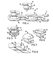
- a conveyor 1 comprises an endless round link chain 2 disposed within a box-like guide track 3 having upwardly-facing surfaces 4 flanking upper portions of alternate links 5a of the chain 2, and article-support members 6 attached indirectly to the alternate links 5a by means of jaw portions 7 gripping elongate members in the form of rods 8 secured to the links.
- Each support member 6 has lower surface portions 9 in slidable contact with the upwardly-facing track surfaces 4.
- the chain 2 which is of steel, comprises interengaging links 5a and 5b of identical form.
- Each link comprises an elongated ring, having two substantially straight sides interconnected by substantially semi-circular end portions.
- the guide track 3 is of plastics material and is provided with an upper, longitudinally-extending slot 15 allowing free passage of the upper portions, (i.e. the uppermost of each straight side), of alternate links 5a.
- the article-support members 6 of this example are of "DELRIN”, (Registered Trade Hark), a plastics material, comprising an acetal resin.
- the conveyor 1 of this example is used to transport bread tins, although other articles, including bread loaves, may be carried on it.
- the plastics material used to form the support members 6 and track 3, ensures that low frictional forces exist between these components and the surfaces 4 over which they slide.
- the material of the members 6 and track 3 is also resilient, has a good resistance to wear, and is non-toxic.
- the link extension rods 8 are received by recesses comprising grooves 16 of part-circular lateral cross-section formed in the article-support members 6. Entry of a rod 8 into a groove l6 is by way of a pair of jaw portions 7 which yield resiliently to allow passage of a rod 8 and thereafter return to their original positions and so hold the rod in place.
- the grooves 16 and jaw portions 7 thereof can be viewed as "snap-fasteners" which secure a member 6 to a rod 8 end thus to a chain link 5a.
- the article-support members 6 are also formed with grooves 17 of substantially semi-circular (lateral) cross-section, which locate the upper portion of a chain link 5a and thus ensure that the member 6 is seated firmly on the link.
- the conveyor 21 illustrated thereby makes use of article-support members 25.
- the members 25 are attached directly to alternate links 5a by means of jaw portions 27 of part-circular grooves 26, which grip the links in a resilient manner, forming "snap" fasteners.
- Each support member 25 has lower surface portions 29 in slideble contact with upwardly-facing surfaces 24 of the track 23. The surfaces 24 may be dispensed with if the members 2 5 are positively secured tc the links 5a by use of a strong bonding material.
- Figures 6 and 7 illustrate further forms of article-support members, namely members 35 and 45 respectively.
- Grooves 36 and 46, jaw portions 37 and 47, and surfaces 39 and 49, correspond to grooves 26, jaw portions 27 and surfaces 29 of Figure 4.
- Hember 35 has a substantially flat upper surface.
- Member 45 has a domed upper surface.
- Figure 8 illustrates a modification wherein opposite ends of a groove 16c of an article-support member 6c are partially closed by end walls 50.
- the end walls 50 serve to limit axial movement of a rod ⁇ within its locating groove 16c.
- the end walls 50 which are integral with the article-support member 6c, have segment-like cut-away portions 51 which allow the member 6c to remain resilient.
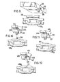
- FIGS 10, 11 and 12 illustrate modifications of the conveyor of Figure 4.
- a spigot 260 extends upwardly from each chain link 205a.
- the spigot 260 is located by a socket 261 formed in the article-support member. 205.
- Figure 11 illustrates a similar modification, wherein a rib 365 extends longitudinally along the upper sides of each link 305a. Each rib 365 is located by a cooperating groove 366 formed in the associated article-support member 305.
- Figures 9, 10 and 11 comprise arrangements wherein extension members (108, 260, 365) are secured to links 105a etc. and the associated article-support members are formed with cooperating recesses (116, 261, 366) for receiving the extension members.
- Figure 12 illustrates an arrangement which, in effect, is a reversal of that shown by Figure 10.
- each article-support member 405 carries a downwardly-extending spigot 370 which is located by a socket 371 formed in the upper side of each associated link 405a.
- one or more features of one conveyor disclosed herein may be substituted for one or more features of another conveyor of the disclosure.
- a pair of endless chains, each carrying a plurality of article-support members, may be employed. However, a single chain can be used if wider support members are provided.
- the conveyor chain(s) are driven by conventional means, (not shown), for example, by wheels, which in turn are driven by sprocket chain drives rotated by electric motors.
- the invention allows chains to change direction and negotiate corners without undue difficulty.
Landscapes
- Engineering & Computer Science (AREA)
- Mechanical Engineering (AREA)
- Chain Conveyers (AREA)
Applications Claiming Priority (2)
| Application Number | Priority Date | Filing Date | Title |
|---|---|---|---|
| GB8504377 | 1985-02-20 | ||
| GB858504377A GB8504377D0 (en) | 1985-02-20 | 1985-02-20 | Conveyors |
Publications (1)
| Publication Number | Publication Date |
|---|---|
| EP0202729A1 true EP0202729A1 (fr) | 1986-11-26 |
Family
ID=10574803
Family Applications (1)
| Application Number | Title | Priority Date | Filing Date |
|---|---|---|---|
| EP19860301182 Withdrawn EP0202729A1 (fr) | 1985-02-20 | 1986-02-20 | Convoyeur à chaîne avec des supports d'articles |
Country Status (2)
| Country | Link |
|---|---|
| EP (1) | EP0202729A1 (fr) |
| GB (1) | GB8504377D0 (fr) |
Cited By (4)
| Publication number | Priority date | Publication date | Assignee | Title |
|---|---|---|---|---|
| NL1001235C2 (nl) * | 1995-09-19 | 1996-09-05 | Langenpac N V | Invoer- en formeerunit voor het uitvoeren van produkten naar een verpakkingsmachine. |
| DE19633298A1 (de) * | 1996-08-19 | 1998-02-26 | Buehler Ag | Förderkette |
| WO2006075912A1 (fr) * | 2005-01-12 | 2006-07-20 | Twentebelt B.V. | Bande transporteuse |
| NL2018816B1 (en) * | 2017-05-01 | 2018-11-09 | Yvon Hoogendijk Interim Man & Coaching | A conveyor having a pulling organ connected to center parts of carrying members. |
Citations (3)
| Publication number | Priority date | Publication date | Assignee | Title |
|---|---|---|---|---|
| DE1000281B (de) * | 1956-02-24 | 1957-01-03 | Hauhinco Maschf | Gliederfoerderband |
| DE1014930B (de) * | 1955-04-21 | 1957-08-29 | Herbert Knaust Dr Ing | Gliederfoerderband mit mittlerer Rundgliederkette |
| DE1060783B (de) * | 1955-01-15 | 1959-07-02 | Ahrens & Bode | Foerderkette, insbesondere zum Foerdern von Milchkannen |
-
1985
- 1985-02-20 GB GB858504377A patent/GB8504377D0/en active Pending
-
1986
- 1986-02-20 EP EP19860301182 patent/EP0202729A1/fr not_active Withdrawn
Patent Citations (3)
| Publication number | Priority date | Publication date | Assignee | Title |
|---|---|---|---|---|
| DE1060783B (de) * | 1955-01-15 | 1959-07-02 | Ahrens & Bode | Foerderkette, insbesondere zum Foerdern von Milchkannen |
| DE1014930B (de) * | 1955-04-21 | 1957-08-29 | Herbert Knaust Dr Ing | Gliederfoerderband mit mittlerer Rundgliederkette |
| DE1000281B (de) * | 1956-02-24 | 1957-01-03 | Hauhinco Maschf | Gliederfoerderband |
Cited By (7)
| Publication number | Priority date | Publication date | Assignee | Title |
|---|---|---|---|---|
| NL1001235C2 (nl) * | 1995-09-19 | 1996-09-05 | Langenpac N V | Invoer- en formeerunit voor het uitvoeren van produkten naar een verpakkingsmachine. |
| WO1997011014A1 (fr) * | 1995-09-19 | 1997-03-27 | Langenpac N.V. | Dispositif pour le transport de marchandises d'une chaine de production a une unite d'emballage |
| DE19633298A1 (de) * | 1996-08-19 | 1998-02-26 | Buehler Ag | Förderkette |
| DE19633298B4 (de) * | 1996-08-19 | 2006-10-19 | Bühler AG | Förderkette |
| WO2006075912A1 (fr) * | 2005-01-12 | 2006-07-20 | Twentebelt B.V. | Bande transporteuse |
| US7658277B2 (en) | 2005-01-12 | 2010-02-09 | Twentebelt B.V. | Conveyor belt |
| NL2018816B1 (en) * | 2017-05-01 | 2018-11-09 | Yvon Hoogendijk Interim Man & Coaching | A conveyor having a pulling organ connected to center parts of carrying members. |
Also Published As
| Publication number | Publication date |
|---|---|
| GB8504377D0 (en) | 1985-03-20 |
Similar Documents
| Publication | Publication Date | Title |
|---|---|---|
| US6216854B1 (en) | Side-flexing conveyor belt | |
| US5004097A (en) | Replaceable snap-on modular overlay for rod and link turn-curve conveyor belts | |
| US5096050A (en) | Low backline pressure chain | |
| EP0631950B1 (fr) | Appareil de transport | |
| EP1182151B1 (fr) | Transporteur à bande courbée | |
| US4909380A (en) | Low backline pressure chain | |
| EP1828031B1 (fr) | Convoyeur a bande a raclettes dont certaines sont segmentees pour permettre un transfert sans discontinuite | |
| US4078654A (en) | Flexible coated wire cable conveyor structure | |
| US4351429A (en) | Conveyor with slip cleats | |
| EP1422171B1 (fr) | Dispositif de transport a chaine avec croisement | |
| EP1375391B1 (fr) | Chaîne destinee a une ligne de transfert tridimensionnelle | |
| EP0066530B1 (fr) | Elément d'une chaîne transporteuse plane avec faible pression d'appui | |
| JP2013126920A (ja) | トラフ形の低摩擦ポジティブドライブベルトを備えるコンベヤ | |
| JPS61145007A (ja) | 運搬メンバ付コンベアベルト | |
| US4524865A (en) | Universal platform chain | |
| EP0558638A1 (fr) | Plaque laterale pour un systeme a bande transporteuse spiralee en plastique. | |
| US5992615A (en) | Curved conveyor section | |
| WO1987003565A1 (fr) | Agencement pour une transporteuse a bande | |
| US6840371B2 (en) | Link having a twisted side guard | |
| EP0202729A1 (fr) | Convoyeur à chaîne avec des supports d'articles | |
| US5593019A (en) | Chain return support | |
| CA2380139C (fr) | Courroie de transport radial avec structure evitant le pincement des griffes | |
| US3973669A (en) | Endless cable conveyor with molded lugs | |
| GB2175560A (en) | Improvements in or relating to conveyors | |
| CA2061680A1 (fr) | Recouvrement modulaire a encliqueter remplacable pour courroies transporteuses avec changement de direction a tiges et a biellettes |
Legal Events
| Date | Code | Title | Description |
|---|---|---|---|
| PUAI | Public reference made under article 153(3) epc to a published international application that has entered the european phase |
Free format text: ORIGINAL CODE: 0009012 |
|
| AK | Designated contracting states |
Kind code of ref document: A1 Designated state(s): DE IT NL |
|
| 17P | Request for examination filed |
Effective date: 19861215 |
|
| 17Q | First examination report despatched |
Effective date: 19871204 |
|
| STAA | Information on the status of an ep patent application or granted ep patent |
Free format text: STATUS: THE APPLICATION IS DEEMED TO BE WITHDRAWN |
|
| 18D | Application deemed to be withdrawn |
Effective date: 19880415 |
|
| RIN1 | Information on inventor provided before grant (corrected) |
Inventor name: KIDDIE, FRANK EDWARD |