EP0202714A1 - Pumpe mit einem elektrisch kontrollierbaren Hubraum - Google Patents
Pumpe mit einem elektrisch kontrollierbaren Hubraum Download PDFInfo
- Publication number
- EP0202714A1 EP0202714A1 EP86200836A EP86200836A EP0202714A1 EP 0202714 A1 EP0202714 A1 EP 0202714A1 EP 86200836 A EP86200836 A EP 86200836A EP 86200836 A EP86200836 A EP 86200836A EP 0202714 A1 EP0202714 A1 EP 0202714A1
- Authority
- EP
- European Patent Office
- Prior art keywords
- pump
- plunger
- chamber
- pump housing
- housing
- Prior art date
- Legal status (The legal status is an assumption and is not a legal conclusion. Google has not performed a legal analysis and makes no representation as to the accuracy of the status listed.)
- Granted
Links
Images
Classifications
-
- H—ELECTRICITY
- H02—GENERATION; CONVERSION OR DISTRIBUTION OF ELECTRIC POWER
- H02K—DYNAMO-ELECTRIC MACHINES
- H02K3/00—Details of windings
- H02K3/30—Windings characterised by the insulating material
-
- F—MECHANICAL ENGINEERING; LIGHTING; HEATING; WEAPONS; BLASTING
- F04—POSITIVE - DISPLACEMENT MACHINES FOR LIQUIDS; PUMPS FOR LIQUIDS OR ELASTIC FLUIDS
- F04B—POSITIVE-DISPLACEMENT MACHINES FOR LIQUIDS; PUMPS
- F04B15/00—Pumps adapted to handle specific fluids, e.g. by selection of specific materials for pumps or pump parts
- F04B15/04—Pumps adapted to handle specific fluids, e.g. by selection of specific materials for pumps or pump parts the fluids being hot or corrosive
-
- F—MECHANICAL ENGINEERING; LIGHTING; HEATING; WEAPONS; BLASTING
- F04—POSITIVE - DISPLACEMENT MACHINES FOR LIQUIDS; PUMPS FOR LIQUIDS OR ELASTIC FLUIDS
- F04B—POSITIVE-DISPLACEMENT MACHINES FOR LIQUIDS; PUMPS
- F04B17/00—Pumps characterised by combination with, or adaptation to, specific driving engines or motors
- F04B17/03—Pumps characterised by combination with, or adaptation to, specific driving engines or motors driven by electric motors
- F04B17/04—Pumps characterised by combination with, or adaptation to, specific driving engines or motors driven by electric motors using solenoids
- F04B17/046—Pumps characterised by combination with, or adaptation to, specific driving engines or motors driven by electric motors using solenoids the fluid flowing through the moving part of the motor
-
- H—ELECTRICITY
- H02—GENERATION; CONVERSION OR DISTRIBUTION OF ELECTRIC POWER
- H02K—DYNAMO-ELECTRIC MACHINES
- H02K33/00—Motors with reciprocating, oscillating or vibrating magnet, armature or coil system
- H02K33/02—Motors with reciprocating, oscillating or vibrating magnet, armature or coil system with armatures moved one way by energisation of a single coil system and returned by mechanical force, e.g. by springs
Definitions
- This invention relates to a pump with an electronically controllable stroke volume which can be used in surroundings where high temperatures and/or high pressures prevail, while the pump must also be resistant to the effect of neutron and gamma radiation.
- a pump for example for applications in nuclear reactor technology, e.g. in simulating failures in nuclear reactors in test set-ups of trial reactors.
- the present invention provides a pump with an electronically controllable stroke volume, comprising a metal pump housing with an intake line and a delivery line, a coil arranged around the bottom part of the pump housing, a one-way valve in said delivery line, a chamber formed in the interior of the housing, said intake line terminating in an upper part of said chamber and said delivery line terminating in a lower part of said chamber, and a plunger mounted in said chamber, said plunger being biased to a first position by a spring, the lower part of the plunger extending within the chamber into the bottom part of the pump housing, and at least the lower part of the plunger being made of a magnetisable material.
- the top of the plunger has an extension in which a passage is formed which forms a connection between the upper part and the lower part of the chamber in the pump housing, and in which passage a one-way valve is provided.
- the one-way valves preferable include spring- biased balls, so that the entire pump only comprises three movable members, that is to say, the plunger and the two balls of the one-way valves.
- the extension of the plunger which extends into the upper part of the chamber in the pump housing, has a pre-determined length, which during the operation of the pump provides for a dynamic seal between the intake side and the delivery side of the pump.
- This dynamic seal renders the use of, e.g., rubber sealing rings unnecessary.
- the coil is wound from metal wire surrounded by a ceramic insulation, e.g. aluminum oxide or magnesium oxide, and a thin outer sheath of metal.
- a ceramic insulation e.g. aluminum oxide or magnesium oxide
- a thin outer sheath of metal e.g. aluminum oxide or magnesium oxide
- Such a wire is known per se for use in water-proof heating elements, but not for use in coils. It has surprisingly been found that a coil wound from this material is very satisfactory and resistant to high temperatures, high pressures and neutron and gamma radiation.
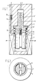
- reference numeral 1 designates the pump housing, which is made of corrosion-resistant metal.
- the pump housing 1 further comprises an intake line 3 and a delivery line 4.
- a chamber for receiving a plunger 5 Formed within the pump housing is a chamber for receiving a plunger 5.
- the lower part of the plunger as viewed in Fig. 1, extends into the bottom part of housing 1 to such an extent that it is surrounded by coil 2.
- Plunger 5 has an extended top portion 5', in which a passage 6 is formed, through which liquid can flow from intake line 3 to the lower part of the chamber.
- Plunger 5 is biased towards a first, uppermost position, in which its collar portion 5" is in contact with the pump housing, by a spring 7, which abuts against a shoulder formed in the chamber of the pump housing.
- a one-way valve comprising a ball 9 loaded by a spring 8 to close passage 6.
- a similar shut-off valve comprising a ball 11 biased by a spring 10 is formed in delivery line 4.
- plunger 5 For a good operation of the pump, it is necessary that at least the part of plunger 5 that is surrounded by coil 2 is made of a magnetisable material, although naturally the entire plunger may be made of this material.
- the operation of the pump according to the invention is as follows.
- an electric voltage pulse is supplied to coil 2, through lines not shown, from a known per se source of voltage, the lower part of the plunger will be pulled against, or down to the vicinity of, the bottom of pump housing 1, against the action of spring 7, by the magnetic field generated by coil 2.
- the liquid present within the chamber in the pump housing is forced through line 4 out of the pump housing, thereby opening the one-way valve in the delivery line.
- the one-way valve in passage 6 prevents liquid from being removed through that conduit.
- the extension 5' of the plunger provides for an effective dynamic seal between the intake side and the delivery side of the pump, without any rubber sealing rings or the like being required for this purpose. Owing to the length of plunger portion 5' and the inertia of the liquid, hardly any liquid flows through the interspace between the chamber wall and the plunger portion 5' during pump action. Pressure variations in the system in which the pump is included have no effect on its operation, because these variations are immediately counterbalanced through the one-way valves in the intake and delivery lines, provided of course these lines are connected to the same system.
- a pump as illustrated in Fig. 1, with a diameter of 40 mm and a length of 112mm.
- the coil was made of 300 windings of a stainless steel coaxial cable with an outer diameter of 1 mm, wound around a non- magnetisable stainless steel core having an inner diameter of 14.6 mm.
- the coil had a resistance of m 7 ohm.
- Supplied to the coil was a block voltage with an amplitude of 30 V and a controllable frequency, whereby a current of 3 Amp flowed through the coil.
- the pump With a frequency of 5 Hz, the pump was found to have a stroke volume of 150 cm 3 /min; at 10 Hz 250 cm 3 / min; and at 20 Hz 350 cm 3 /min. It further turned out that the stroke volume could also be varied by varying the amount of the supply voltage, because with such a variation the plunger is pulled farther or less far in the direction of the bottom of the pump housing.
- the pump was further found to be resistant to internal or external pressures of up to 200 bar and temperatures of about 400°C. In principle the pump is resistant to still higher temperatures, but at such high temperatures the magnetic properties of the plunger are adversely affected. As the pump is fully made of corrosion-resistant metal and ceramic material it is also resistant to the effect of gamma radiation and neutron radiation of a high intensity as occurring in nuclear plants.
- the pump according to the invention has been described for use in a nuclear reactor, it is naturally suitable for other purposes, in particular for use in corrosive liquids and/or at high temperatures and/or at high pressures. Also, the pump can be given dimensions different from the above without adversely affecting its good operation.
Landscapes
- Engineering & Computer Science (AREA)
- Power Engineering (AREA)
- Mechanical Engineering (AREA)
- General Engineering & Computer Science (AREA)
- Physics & Mathematics (AREA)
- Fluid Mechanics (AREA)
- Details Of Reciprocating Pumps (AREA)
Applications Claiming Priority (2)
| Application Number | Priority Date | Filing Date | Title |
|---|---|---|---|
| NL8501402 | 1985-05-15 | ||
| NL8501402A NL8501402A (nl) | 1985-05-15 | 1985-05-15 | Pomp met elektronisch regelbaar slagvolume. |
Publications (2)
| Publication Number | Publication Date |
|---|---|
| EP0202714A1 true EP0202714A1 (de) | 1986-11-26 |
| EP0202714B1 EP0202714B1 (de) | 1989-08-16 |
Family
ID=19845995
Family Applications (1)
| Application Number | Title | Priority Date | Filing Date |
|---|---|---|---|
| EP19860200836 Expired EP0202714B1 (de) | 1985-05-15 | 1986-05-14 | Pumpe mit einem elektrisch kontrollierbaren Hubraum |
Country Status (3)
| Country | Link |
|---|---|
| EP (1) | EP0202714B1 (de) |
| DE (1) | DE3665092D1 (de) |
| NL (1) | NL8501402A (de) |
Cited By (7)
| Publication number | Priority date | Publication date | Assignee | Title |
|---|---|---|---|---|
| WO1995026462A1 (en) * | 1994-03-29 | 1995-10-05 | Orbital Engine Company (Australia) Pty. Limited | Two-section pump |
| CN1093913C (zh) * | 1996-12-31 | 2002-11-06 | 万都空调株式会社 | 空调机用压缩机 |
| FR2919356A1 (fr) * | 2007-07-26 | 2009-01-30 | Suntec Ind France Soc Par Acti | Pompe modulante a liquide |
| WO2009054633A2 (en) | 2007-10-24 | 2009-04-30 | Lg Electronics, Inc. | Reciprocating compressor |
| WO2012171757A1 (de) * | 2011-06-16 | 2012-12-20 | Robert Bosch Gmbh | Förderaggregat für betriebs-/hilfsstoffe für verwendungskraftmaschinen |
| WO2021099025A1 (de) * | 2019-11-19 | 2021-05-27 | Voith Patent Gmbh | Elektrohydraulischer aktuator für den einsatz unter wasser und elektrisch angetriebene pumpe für einen solchen elektrohydraulischen aktuator |
| US20230417231A1 (en) * | 2022-06-22 | 2023-12-28 | Prominent Gmbh | Potential equalization for a metering pump |
Citations (5)
| Publication number | Priority date | Publication date | Assignee | Title |
|---|---|---|---|---|
| LU30732A1 (de) * | ||||
| CH114171A (de) * | 1925-02-23 | 1926-04-01 | Charles Schaer | Elektromotor zum Antrieb von Kältemaschinen und Verfahren zur Herstellung desselben. |
| US2293684A (en) * | 1940-05-13 | 1942-08-18 | Galvin Mfg Corp | Electromagnetic pump |
| GB827784A (en) * | 1957-06-05 | 1960-02-10 | Atomic Energy Authority Uk | Improvements in or relating to electric pumps |
| DE1290820B (de) * | 1964-05-13 | 1969-03-13 | Eckerle Otto | Elektromagnetisch angetriebene Kolbenpumpe |
-
1985
- 1985-05-15 NL NL8501402A patent/NL8501402A/nl not_active Application Discontinuation
-
1986
- 1986-05-14 EP EP19860200836 patent/EP0202714B1/de not_active Expired
- 1986-05-14 DE DE8686200836T patent/DE3665092D1/de not_active Expired
Patent Citations (5)
| Publication number | Priority date | Publication date | Assignee | Title |
|---|---|---|---|---|
| LU30732A1 (de) * | ||||
| CH114171A (de) * | 1925-02-23 | 1926-04-01 | Charles Schaer | Elektromotor zum Antrieb von Kältemaschinen und Verfahren zur Herstellung desselben. |
| US2293684A (en) * | 1940-05-13 | 1942-08-18 | Galvin Mfg Corp | Electromagnetic pump |
| GB827784A (en) * | 1957-06-05 | 1960-02-10 | Atomic Energy Authority Uk | Improvements in or relating to electric pumps |
| DE1290820B (de) * | 1964-05-13 | 1969-03-13 | Eckerle Otto | Elektromagnetisch angetriebene Kolbenpumpe |
Cited By (10)
| Publication number | Priority date | Publication date | Assignee | Title |
|---|---|---|---|---|
| WO1995026462A1 (en) * | 1994-03-29 | 1995-10-05 | Orbital Engine Company (Australia) Pty. Limited | Two-section pump |
| US6095769A (en) * | 1994-03-29 | 2000-08-01 | Orbital Engine Co. (Australia) Pty Limited | Two section pump |
| CN1093913C (zh) * | 1996-12-31 | 2002-11-06 | 万都空调株式会社 | 空调机用压缩机 |
| FR2919356A1 (fr) * | 2007-07-26 | 2009-01-30 | Suntec Ind France Soc Par Acti | Pompe modulante a liquide |
| WO2009044016A3 (fr) * | 2007-07-26 | 2009-06-11 | Suntec Ind France | Pompe modulante a liquide |
| WO2009054633A2 (en) | 2007-10-24 | 2009-04-30 | Lg Electronics, Inc. | Reciprocating compressor |
| EP2203970A4 (de) * | 2007-10-24 | 2014-05-28 | Lg Electronics Inc | Hubkolbenverdichter |
| WO2012171757A1 (de) * | 2011-06-16 | 2012-12-20 | Robert Bosch Gmbh | Förderaggregat für betriebs-/hilfsstoffe für verwendungskraftmaschinen |
| WO2021099025A1 (de) * | 2019-11-19 | 2021-05-27 | Voith Patent Gmbh | Elektrohydraulischer aktuator für den einsatz unter wasser und elektrisch angetriebene pumpe für einen solchen elektrohydraulischen aktuator |
| US20230417231A1 (en) * | 2022-06-22 | 2023-12-28 | Prominent Gmbh | Potential equalization for a metering pump |
Also Published As
| Publication number | Publication date |
|---|---|
| DE3665092D1 (en) | 1989-09-21 |
| EP0202714B1 (de) | 1989-08-16 |
| NL8501402A (nl) | 1986-12-01 |
Similar Documents
| Publication | Publication Date | Title |
|---|---|---|
| US3361161A (en) | Chlorinating valve | |
| DE4404938C2 (de) | Betriebsüberwachungssystem für Fertigungseinrichtungen, das in einer korrosiven Umgebung arbeitet | |
| CN208315367U (zh) | 一种全密封油浸式变压器用多功能保护装置 | |
| US4067541A (en) | Water valve operating solenoid | |
| US4808089A (en) | Reciprocating pump for a medication administering device | |
| EP0202714A1 (de) | Pumpe mit einem elektrisch kontrollierbaren Hubraum | |
| CN106197579B (zh) | 具有弹簧激发的密封环的磁性流量计流量管组件 | |
| US3408053A (en) | Liquid level float control | |
| KR20140117372A (ko) | 쌍극 쌍투 근접 스위치 | |
| US4353523A (en) | Flow regulator | |
| EP1503122B1 (de) | Ventil | |
| US3095902A (en) | Corrosion resistant valve | |
| US3776267A (en) | Pressure transfer unit with bellows | |
| US3698682A (en) | Solenoid actuated valve for anhydrous ammonia flow meters | |
| GB2062823A (en) | Coffee maker | |
| US4117720A (en) | Electric measuring device having a small-bore liquid container with improved electrode sealing means | |
| DE3941634A1 (de) | Schallisolierte halterung eines ultraschallwandlers | |
| DE2838723A1 (de) | Fluessigkeitsstand-signalgeber | |
| CN218481780U (zh) | 一种智能液位控制器 | |
| US4289451A (en) | External tank level control system | |
| CN217272237U (zh) | 一种隔膜阀 | |
| US3245427A (en) | Operator apparatus | |
| EP0556862B1 (de) | Verbinderanordnung für motorgetriebene Pumpe | |
| US3625636A (en) | Liquid level regulating system | |
| US4579640A (en) | Electrostatic water treater |
Legal Events
| Date | Code | Title | Description |
|---|---|---|---|
| PUAI | Public reference made under article 153(3) epc to a published international application that has entered the european phase |
Free format text: ORIGINAL CODE: 0009012 |
|
| AK | Designated contracting states |
Kind code of ref document: A1 Designated state(s): DE FR GB IT NL |
|
| 17P | Request for examination filed |
Effective date: 19870514 |
|
| 17Q | First examination report despatched |
Effective date: 19880209 |
|
| GRAA | (expected) grant |
Free format text: ORIGINAL CODE: 0009210 |
|
| AK | Designated contracting states |
Kind code of ref document: B1 Designated state(s): DE FR GB IT NL |
|
| REF | Corresponds to: |
Ref document number: 3665092 Country of ref document: DE Date of ref document: 19890921 |
|
| ET | Fr: translation filed | ||
| ITF | It: translation for a ep patent filed | ||
| PGFP | Annual fee paid to national office [announced via postgrant information from national office to epo] |
Ref country code: GB Payment date: 19900410 Year of fee payment: 5 |
|
| PGFP | Annual fee paid to national office [announced via postgrant information from national office to epo] |
Ref country code: FR Payment date: 19900417 Year of fee payment: 5 |
|
| ITTA | It: last paid annual fee | ||
| PGFP | Annual fee paid to national office [announced via postgrant information from national office to epo] |
Ref country code: NL Payment date: 19900531 Year of fee payment: 5 |
|
| PLBE | No opposition filed within time limit |
Free format text: ORIGINAL CODE: 0009261 |
|
| STAA | Information on the status of an ep patent application or granted ep patent |
Free format text: STATUS: NO OPPOSITION FILED WITHIN TIME LIMIT |
|
| PGFP | Annual fee paid to national office [announced via postgrant information from national office to epo] |
Ref country code: DE Payment date: 19900626 Year of fee payment: 5 |
|
| 26N | No opposition filed | ||
| PG25 | Lapsed in a contracting state [announced via postgrant information from national office to epo] |
Ref country code: GB Effective date: 19910514 |
|
| PG25 | Lapsed in a contracting state [announced via postgrant information from national office to epo] |
Ref country code: NL Effective date: 19911201 |
|
| GBPC | Gb: european patent ceased through non-payment of renewal fee | ||
| NLV4 | Nl: lapsed or anulled due to non-payment of the annual fee | ||
| PG25 | Lapsed in a contracting state [announced via postgrant information from national office to epo] |
Ref country code: FR Effective date: 19920131 |
|
| PG25 | Lapsed in a contracting state [announced via postgrant information from national office to epo] |
Ref country code: DE Effective date: 19920303 |
|
| REG | Reference to a national code |
Ref country code: FR Ref legal event code: ST |
|
| PG25 | Lapsed in a contracting state [announced via postgrant information from national office to epo] |
Ref country code: IT Free format text: LAPSE BECAUSE OF NON-PAYMENT OF DUE FEES;WARNING: LAPSES OF ITALIAN PATENTS WITH EFFECTIVE DATE BEFORE 2007 MAY HAVE OCCURRED AT ANY TIME BEFORE 2007. THE CORRECT EFFECTIVE DATE MAY BE DIFFERENT FROM THE ONE RECORDED. Effective date: 20050514 |