EP0201989B1 - Ultrasonic range finding - Google Patents
Ultrasonic range finding Download PDFInfo
- Publication number
- EP0201989B1 EP0201989B1 EP86301766A EP86301766A EP0201989B1 EP 0201989 B1 EP0201989 B1 EP 0201989B1 EP 86301766 A EP86301766 A EP 86301766A EP 86301766 A EP86301766 A EP 86301766A EP 0201989 B1 EP0201989 B1 EP 0201989B1
- Authority
- EP
- European Patent Office
- Prior art keywords
- reference signal
- target
- signals
- echo
- components
- Prior art date
- Legal status (The legal status is an assumption and is not a legal conclusion. Google has not performed a legal analysis and makes no representation as to the accuracy of the status listed.)
- Expired - Lifetime
Links
Images

Classifications
-
- G—PHYSICS
- G01—MEASURING; TESTING
- G01S—RADIO DIRECTION-FINDING; RADIO NAVIGATION; DETERMINING DISTANCE OR VELOCITY BY USE OF RADIO WAVES; LOCATING OR PRESENCE-DETECTING BY USE OF THE REFLECTION OR RERADIATION OF RADIO WAVES; ANALOGOUS ARRANGEMENTS USING OTHER WAVES
- G01S15/00—Systems using the reflection or reradiation of acoustic waves, e.g. sonar systems
- G01S15/02—Systems using the reflection or reradiation of acoustic waves, e.g. sonar systems using reflection of acoustic waves
- G01S15/06—Systems determining the position data of a target
- G01S15/08—Systems for measuring distance only
- G01S15/32—Systems for measuring distance only using transmission of continuous waves, whether amplitude-, frequency-, or phase-modulated, or unmodulated
- G01S15/36—Systems for measuring distance only using transmission of continuous waves, whether amplitude-, frequency-, or phase-modulated, or unmodulated with phase comparison between the received signal and the contemporaneously transmitted signal
-
- G—PHYSICS
- G01—MEASURING; TESTING
- G01S—RADIO DIRECTION-FINDING; RADIO NAVIGATION; DETERMINING DISTANCE OR VELOCITY BY USE OF RADIO WAVES; LOCATING OR PRESENCE-DETECTING BY USE OF THE REFLECTION OR RERADIATION OF RADIO WAVES; ANALOGOUS ARRANGEMENTS USING OTHER WAVES
- G01S15/00—Systems using the reflection or reradiation of acoustic waves, e.g. sonar systems
- G01S15/02—Systems using the reflection or reradiation of acoustic waves, e.g. sonar systems using reflection of acoustic waves
- G01S15/06—Systems determining the position data of a target
- G01S15/08—Systems for measuring distance only
- G01S15/10—Systems for measuring distance only using transmission of interrupted, pulse-modulated waves
Definitions
- This invention relates to ultrasonic range finding.
- phase measuring method involves the use of continuous waves of constant frequency and comparing the phase displacement of the echo with respect to the transmitted signal. This necessarily entails the use of separate transmitters and receivers and, in addition, if the range is greater than one wavelength, the approximate distance must be known.
- the object of the present invention is to provide an improved method and apparatus for ultrasonic range finding.
- a method of ultrasonic range finding of a target immersed in liquid metal and comprising transmitting ultrasonic signals to the target, receiving the signals following reflection by the target, and analysing the signals to derive a measure of the range of the target is characterised by generating a reference signal having a periodic waveform, extracting a portion of the reference signal and applying it to transducer means so as to produce an ultrasound pulse which is directed towards said target, receiving the echo signal returned by the target, sustaining the reference signal for a period longer than the time taken for the ultrasound pulse to reach the target and for the echo signal to return from the target, determining the pulse echo transit time and the phase displacement of the echo signal with respect to the reference signal; and combining the transit time and phase displacement information to derive a measure of the range of the target.
- the same transducer is used to send and receive the pulse and echo signals.
- One application of the invention is in the measurement of displacements between stressed structural components within a nuclear reactor as described hereinafter.
- the reactor as illustrated diagrammatically, comprises a reactor vessel 10 provided with a core 12 mounted on support structure 14 beneath the above-core structure 16 (incorporating control rods etc).
- the reactor also includes the usual liquid metal pumps 18 and heat exchangers 20.
- the support structure There is a need for the support structure to be examined on a regular routine basis to detect any relative movements between those components of the structure which are subject to stress.
- the structural components 22, 24 may be routinely inspected for such displacement.
- Such inspections can be carried out by ultrasonically measuring the spacing between the components 22,24 or, more particularly, between reflectors 26, 28 attached to the components and comparing with previously made measurements to detect any variation with time.
- This can be achieved by positioning an ultrasonic transducer assembly 30 between the reflectors 26, 28, the assembly comprising a pair of transducers located back to back so that they emit ultrasound in opposite directions.
- the transducer assembly 30 is positioned by means of a manipulator device 32 which may comprise a series of interconnected links insertable into the reactor via a vertical mast (not shown) extending through the reactor roof, the links being so designed that the manipulator is flexible in one direction and rigid in the opposite direction so that it can be extended in the manner of a cantilever arm.
- the manipulator may include an articulated joint or joints to enable the assembly 30 to be orientated such that the ultrasound beams emitted by the transducers are incident at substantially 90° on the reflector plates 26, 28.
- the optimum orientation of the transducer assembly may be obtained by adjusting the manipulator until the echo signals from the reflectors are maximised.
- the actual location of the transducer assembly 30 between the reflectors 26, 28 is not important in terms of obtaining accurate measurement of the distance between the reflectors.
- the transducers are orientated for 90° incidence on the reflectors.
- the latter consideration may be less significant if, instead of being flat as illustrated in Figure 4, the reflectors 26, 28 are spherical but, in this event, the location of the assembly 30 between the reflectors may be more important because of the desirability of locating each transducer at the centre of curvature of the associated reflector.
- this illustrates the electronic circuitry associated with each transducer 32 of the assembly 30.
- the transducer 32 is of the send-receive type and is connect to a high frequency oscillator 34 (typically 5 MHz) via a gate 36 whose width is controlled by circuit 38 which enables the width to be varied if desired.
- the oscillator 34 is controlled by a square wave generator 40 so that the ouptut of the oscillator is delivered in bursts governed by the mark-space ratio of the generator 40.
- the square wave output 42 of the generator 40 defines the start 44 and end 46 of the oscillator signal bursts which may be sinusoidal.
- the width of each burst is selected so as to be in excess of the time taken for a transmitted pulse from the transducer 32 to travel out to its associated reflector and back again.
- the oscillator bursts are gated by gate 36, the gate pulses 48 being depicted by reference numeral 48 in Figure 2C.
- the gate pulses 48 may be delayed slightly with respect to the leading edges of the square wave 42 but will be arranged so that both the gated pulse and theecho fall within the same signal burst from the oscillator 34 and preferably so that the leading edge of the gate pulse coincides with a predetermined point on the reference signal waveform (preferably the zero cross-over is used since the result of gating at this point will result in the gated portion having a harmonic content which can be transmitted by the transducer).
- the gate 36 serves to isolate a few cycles of the signal burst and apply the gated portion 50 (see Figure 2D) to the transducer 32 which then generates a pulse of ultrasound in phase with the oscillator 34.
- the oscillator output serves as a reference signal for detection of phase differences between the reference and the echo.
- the echo signals depicted by reference numeral 52 in Figure 2D, are fed from the transducer 32 ia an amplifier 54 to an oscilloscope 56, transit time circuitry 58 and a phase sensitive detector 60 which also receives the reference signals from the oscillator 34 and serves to produce a signal on line 62 representing the phase shift of the echo signal 52 with respect to the reference signal.
- the output of detector 60 and transit time circuitry 58 are fed to a computer 64 which combines the coarse distance measurement represented by the pulse transit time with the fine measurement obtained from the detector 60 to derive a high precision result with a typical accuracy of the order of a small fraction of a wavelength (of the oscillator signal).
- the range of the target ie the associated reflector, may be stored in terms of a time measurement or it may be converted to a distance measurement as such by multiplying the time by the velocity of sound in the medium (eg liquid sodium).
- a send-receive transducer is associated with each reflector, separate transmitting and receiving transducers may be used instead.
- a calibration procedure may be carried out in the same environment.
- the calibration may be achieved by positioning the assembly 30 between two reflectors secured to reactor internals which are unstressed, the reflectors being located a precise, known distance apart.
- the assembly 30 is used to obtain a measurement of this distance thereby enabling the equipment to be calibrated in terms of the known spacing.
Description
- It is well-known to measure range by measuring the transit time taken for an ultrasound pulse travel to and return from a target. It is also known to employ a phase measuring method, as described in "Ultrasonic Testing of Materials" (J and H Krautkramer), Third Edition, Page 286. The known phase measuring method involves the use of continuous waves of constant frequency and comparing the phase displacement of the echo with respect to the transmitted signal. This necessarily entails the use of separate transmitters and receivers and, in addition, if the range is greater than one wavelength, the approximate distance must be known.
- The object of the present invention is to provide an improved method and apparatus for ultrasonic range finding.
- According to one aspect of the present invention, a method of ultrasonic range finding of a target immersed in liquid metal and comprising transmitting ultrasonic signals to the target, receiving the signals following reflection by the target, and analysing the signals to derive a measure of the range of the target, is characterised by generating a reference signal having a periodic waveform, extracting a portion of the reference signal and applying it to transducer means so as to produce an ultrasound pulse which is directed towards said target, receiving the echo signal returned by the target, sustaining the reference signal for a period longer than the time taken for the ultrasound pulse to reach the target and for the echo signal to return from the target, determining the pulse echo transit time and the phase displacement of the echo signal with respect to the reference signal; and combining the transit time and phase displacement information to derive a measure of the range of the target.
- Preferably the same transducer is used to send and receive the pulse and echo signals.
- According to a second aspect of the invention there is provided a method of obtaining a measure of the spacing between two components, as defined in Claim 8.
- One application of the invention is in the measurement of displacements between stressed structural components within a nuclear reactor as described hereinafter.
- The invention will now be described by way of example only with reference to the accompanying drawings, in which:
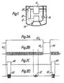
- Figure 1 is a diagrammatic view illustrating the general layout of a pool-type liquid metal cooled fast breeder reactor;
- Figure 2A-2D illustrate various waveforms;
- Figure 3 is a schematic block diagram of electronic circuitry for driving an ultrasonic transducer and deriving distance measurements from the reflected ultrasound; and
- Figure 4 is a diagrammatic view illustrating the measurement of any displacement between components of the core support structure in a reactor.
- Referring to Figure 1 the reactor, as illustrated diagrammatically, comprises a
reactor vessel 10 provided with acore 12 mounted onsupport structure 14 beneath the above-core structure 16 (incorporating control rods etc). The reactor also includes the usualliquid metal pumps 18 andheat exchangers 20. There is a need for the support structure to be examined on a regular routine basis to detect any relative movements between those components of the structure which are subject to stress. Thus, for example, as shown in Figure 4, thestructural components - Such inspections can be carried out by ultrasonically measuring the spacing between the
components reflectors ultrasonic transducer assembly 30 between thereflectors transducer assembly 30 is positioned by means of amanipulator device 32 which may comprise a series of interconnected links insertable into the reactor via a vertical mast (not shown) extending through the reactor roof, the links being so designed that the manipulator is flexible in one direction and rigid in the opposite direction so that it can be extended in the manner of a cantilever arm. - A links manipulator of this type is described for example in Liquid Metal Engineering and Technology, British Nuclear Engineering Society 1984, Pages 423-430, the article being entitled "Recent advances in the technology of under-sodium inspection in LMFBRs" by McKnight et al. The manipulator may include an articulated joint or joints to enable the
assembly 30 to be orientated such that the ultrasound beams emitted by the transducers are incident at substantially 90° on thereflector plates transducer assembly 30 between thereflectors reflectors assembly 30 between the reflectors may be more important because of the desirability of locating each transducer at the centre of curvature of the associated reflector. - Referring to Figure 3, this illustrates the electronic circuitry associated with each
transducer 32 of theassembly 30. Thetransducer 32 is of the send-receive type and is connect to a high frequency oscillator 34 (typically 5 MHz) via agate 36 whose width is controlled bycircuit 38 which enables the width to be varied if desired. The oscillator 34 is controlled by a square wave generator 40 so that the ouptut of the oscillator is delivered in bursts governed by the mark-space ratio of the generator 40. Thus, as shown in Figures 2A and 2B, the square wave output 42 of the generator 40 defines thestart 44 andend 46 of the oscillator signal bursts which may be sinusoidal. The width of each burst is selected so as to be in excess of the time taken for a transmitted pulse from thetransducer 32 to travel out to its associated reflector and back again. - The oscillator bursts are gated by
gate 36, thegate pulses 48 being depicted byreference numeral 48 in Figure 2C. Thegate pulses 48 may be delayed slightly with respect to the leading edges of the square wave 42 but will be arranged so that both the gated pulse and theecho fall within the same signal burst from the oscillator 34 and preferably so that the leading edge of the gate pulse coincides with a predetermined point on the reference signal waveform (preferably the zero cross-over is used since the result of gating at this point will result in the gated portion having a harmonic content which can be transmitted by the transducer). Thegate 36 serves to isolate a few cycles of the signal burst and apply the gated portion 50 (see Figure 2D) to thetransducer 32 which then generates a pulse of ultrasound in phase with the oscillator 34. It will be understood that the oscillator output serves as a reference signal for detection of phase differences between the reference and the echo. The echo signals, depicted byreference numeral 52 in Figure 2D, are fed from thetransducer 32 ia anamplifier 54 to anoscilloscope 56,transit time circuitry 58 and a phasesensitive detector 60 which also receives the reference signals from the oscillator 34 and serves to produce a signal online 62 representing the phase shift of theecho signal 52 with respect to the reference signal. - The output of
detector 60 andtransit time circuitry 58 are fed to a computer 64 which combines the coarse distance measurement represented by the pulse transit time with the fine measurement obtained from thedetector 60 to derive a high precision result with a typical accuracy of the order of a small fraction of a wavelength (of the oscillator signal). The range of the target, ie the associated reflector, may be stored in terms of a time measurement or it may be converted to a distance measurement as such by multiplying the time by the velocity of sound in the medium (eg liquid sodium). An indication of the perpendicular spacing (either in terms of time or distance) between the reflectors may then be derived by summing the measurements made by both transducers, it will be understood that the overall result will be independent of the precise position of thetransducer assembly 30 between the two reflectors. - Although, in the illustrated embodiment, a send-receive transducer is associated with each reflector, separate transmitting and receiving transducers may be used instead.
- Prior to effecting measurement of the spacing between the reflectors, a calibration procedure may be carried out in the same environment. The calibration may be achieved by positioning the
assembly 30 between two reflectors secured to reactor internals which are unstressed, the reflectors being located a precise, known distance apart. Theassembly 30 is used to obtain a measurement of this distance thereby enabling the equipment to be calibrated in terms of the known spacing.
Claims (8)
Applications Claiming Priority (4)
| Application Number | Priority Date | Filing Date | Title |
|---|---|---|---|
| GB08509445A GB2173594A (en) | 1985-04-12 | 1985-04-12 | Ultrasonic measurement of the spacing between two components |
| GB8509447 | 1985-04-12 | ||
| GB08509447A GB2173595B (en) | 1985-04-12 | 1985-04-12 | Ultrasonic range finding |
| GB8509445 | 1985-04-12 |
Publications (3)
| Publication Number | Publication Date |
|---|---|
| EP0201989A2 EP0201989A2 (en) | 1986-11-20 |
| EP0201989A3 EP0201989A3 (en) | 1987-09-23 |
| EP0201989B1 true EP0201989B1 (en) | 1991-01-16 |
Family
ID=26289118
Family Applications (1)
| Application Number | Title | Priority Date | Filing Date |
|---|---|---|---|
| EP86301766A Expired - Lifetime EP0201989B1 (en) | 1985-04-12 | 1986-03-12 | Ultrasonic range finding |
Country Status (3)
| Country | Link |
|---|---|
| US (1) | US4831604A (en) |
| EP (1) | EP0201989B1 (en) |
| DE (1) | DE3676866D1 (en) |
Families Citing this family (8)
| Publication number | Priority date | Publication date | Assignee | Title |
|---|---|---|---|---|
| US5418758A (en) * | 1991-03-22 | 1995-05-23 | Connell Wagner (Old) Pty. Ltd. | Distance measurement system |
| JP2735758B2 (en) * | 1992-11-25 | 1998-04-02 | 防衛庁技術研究本部長 | Method for compensating fluctuation of synthetic aperture radar and position measurement method using radar |
| DE4407369C2 (en) * | 1994-03-05 | 1999-09-30 | Grieshaber Vega Kg | Method and circuit arrangement for measuring the transit time and their use |
| DE4433775A1 (en) * | 1994-09-22 | 1996-03-28 | Daimler Benz Ag | Pulse radar method |
| DE4437205A1 (en) * | 1994-10-18 | 1996-04-25 | Walter Prof Dr Kaestel | Ultrasonic displacement measuring unit consisting of ultrasonic transmitter and receiver |
| US6104671A (en) * | 1996-03-28 | 2000-08-15 | Reed W. Hoyt | Apparatus and method for measuring the relative velocity and true distance between two objects |
| US6793177B2 (en) | 2002-11-04 | 2004-09-21 | The Bonutti 2003 Trust-A | Active drag and thrust modulation system and method |
| DE102011004830B4 (en) | 2011-02-28 | 2015-10-29 | Holger Löhmer | Phase method for measuring the propagation velocity of sound waves with dynamic measurement window |
Family Cites Families (15)
| Publication number | Priority date | Publication date | Assignee | Title |
|---|---|---|---|---|
| US3181114A (en) * | 1960-07-26 | 1965-04-27 | Bunker Ramo | Ultrasonic distance measurement method and apparatus |
| DE1274353B (en) * | 1964-06-13 | 1968-08-01 | Standard Elektrik Lorenz Ag | Device for distance measurement working according to the transit time method |
| US3555500A (en) * | 1968-12-27 | 1971-01-12 | Bendix Corp | Sonar detection system |
| US3517767A (en) * | 1969-04-04 | 1970-06-30 | Mobil Oil Corp | Caliper system for focusing dual transducers in logging tool |
| US3934457A (en) * | 1975-01-13 | 1976-01-27 | General Electric Company | Vessel nozzle inspection apparatus |
| JPS5462487A (en) * | 1977-10-26 | 1979-05-19 | Toshiba Corp | Reactor |
| JPS5845645B2 (en) * | 1978-03-27 | 1983-10-12 | 株式会社東芝 | core components |
| US4287769A (en) * | 1978-06-01 | 1981-09-08 | Massachusetts Institute Of Technology | Apparatus and method whereby wave energy is correlated with geometry of a manufactured part or the like or to positional relationships in a system |
| US4302286A (en) * | 1979-04-24 | 1981-11-24 | Westinghouse Electric Corp. | Reactor vessel in-service inspection assembly and ultrasonic centering device |
| DE3022857A1 (en) * | 1979-08-29 | 1981-04-02 | EUMIG Elektrizitäts- und Metallwaren-Industrie GmbH, Wiener Neudorf | DEVICE FOR MEASURING TIME |
| US4494224A (en) * | 1982-07-16 | 1985-01-15 | Morrell David J | Pipe measuring method and apparatus |
| US4574368A (en) * | 1983-02-23 | 1986-03-04 | Record Industrial Company | Distance measuring system using ultrasonic ranging |
| GB8314320D0 (en) * | 1983-05-24 | 1983-06-29 | British Nuclear Fuels Ltd | Pumping system |
| US4493849A (en) * | 1983-10-21 | 1985-01-15 | Warner-Lambert Company | Process for preparing a non-chalky, organoleptically pleasing chewing gum composition |
| GB8412608D0 (en) * | 1984-05-17 | 1984-06-20 | Nat Nuclear Corp Ltd | Scanning device |
-
1986
- 1986-03-12 DE DE8686301766T patent/DE3676866D1/en not_active Expired - Fee Related
- 1986-03-12 EP EP86301766A patent/EP0201989B1/en not_active Expired - Lifetime
- 1986-03-17 US US06/840,148 patent/US4831604A/en not_active Expired - Fee Related
Also Published As
| Publication number | Publication date |
|---|---|
| US4831604A (en) | 1989-05-16 |
| DE3676866D1 (en) | 1991-02-21 |
| EP0201989A2 (en) | 1986-11-20 |
| EP0201989A3 (en) | 1987-09-23 |
Similar Documents
| Publication | Publication Date | Title |
|---|---|---|
| US5497662A (en) | Method and apparatus for measuring and controlling refracted angle of ultrasonic waves | |
| US3944963A (en) | Method and apparatus for ultrasonically measuring deviation from straightness, or wall curvature or axial curvature, of an elongated member | |
| CA1078953A (en) | Apparatus for measuring the radial dimensions of a cylindrical tube by ultrasonics | |
| CN101943680B (en) | Array ultrasonic flaw detection method and system with temperature compensation | |
| EP0201989B1 (en) | Ultrasonic range finding | |
| US11408861B2 (en) | Transducer and transducer arrangement for ultrasonic probe systems, ultrasonic probe system and inspection method | |
| US4702112A (en) | Ultrasonic phase reflectoscope | |
| JPS6236527B2 (en) | ||
| US4531411A (en) | Acoustic emission linear pulse holography | |
| US3651687A (en) | Ultrasonic micrometer | |
| US4655992A (en) | Remote temperature measurement | |
| US4864862A (en) | Boresonic inspection system | |
| GB2173595A (en) | Ultrasonic range finding | |
| JPH01156661A (en) | Joint part survey instrument | |
| Mech et al. | Development of ultrasonic examination methods for austenitic stainless steel weld inspection | |
| US6829940B2 (en) | Method and apparatus for measuring surface wave traveling time | |
| GB2173594A (en) | Ultrasonic measurement of the spacing between two components | |
| JPS6014166A (en) | Method and device for ultrasonic flaw detection | |
| RU2084821C1 (en) | Ultrasonic meter for measuring clearances in multi-layer structures | |
| CA1303721C (en) | Boresonic inspection system | |
| RU2687086C1 (en) | Method of ultrasonic monitoring of pipeline wall thickness | |
| JPH02150766A (en) | Ultrasonic flaw detecting device | |
| CN204832117U (en) | Higher order mode lamb wave welding seam detecting system | |
| SU1293630A1 (en) | Method of ultrasonic checking of articles | |
| Silk | The role of ultrasonic diffraction in NDT |
Legal Events
| Date | Code | Title | Description |
|---|---|---|---|
| PUAI | Public reference made under article 153(3) epc to a published international application that has entered the european phase |
Free format text: ORIGINAL CODE: 0009012 |
|
| AK | Designated contracting states |
Kind code of ref document: A2 Designated state(s): DE FR IT |
|
| PUAL | Search report despatched |
Free format text: ORIGINAL CODE: 0009013 |
|
| AK | Designated contracting states |
Kind code of ref document: A3 Designated state(s): DE FR IT |
|
| 17P | Request for examination filed |
Effective date: 19880229 |
|
| 17Q | First examination report despatched |
Effective date: 19891117 |
|
| GRAA | (expected) grant |
Free format text: ORIGINAL CODE: 0009210 |
|
| AK | Designated contracting states |
Kind code of ref document: B1 Designated state(s): DE FR IT |
|
| ITF | It: translation for a ep patent filed |
Owner name: JACOBACCI & PERANI S.P.A. |
|
| ET | Fr: translation filed | ||
| REF | Corresponds to: |
Ref document number: 3676866 Country of ref document: DE Date of ref document: 19910221 |
|
| PLBE | No opposition filed within time limit |
Free format text: ORIGINAL CODE: 0009261 |
|
| STAA | Information on the status of an ep patent application or granted ep patent |
Free format text: STATUS: NO OPPOSITION FILED WITHIN TIME LIMIT |
|
| PG25 | Lapsed in a contracting state [announced via postgrant information from national office to epo] |
Ref country code: FR Effective date: 19911129 |
|
| PG25 | Lapsed in a contracting state [announced via postgrant information from national office to epo] |
Ref country code: DE Effective date: 19920101 |
|
| 26N | No opposition filed | ||
| REG | Reference to a national code |
Ref country code: FR Ref legal event code: ST |
|
| PG25 | Lapsed in a contracting state [announced via postgrant information from national office to epo] |
Ref country code: IT Free format text: LAPSE BECAUSE OF NON-PAYMENT OF DUE FEES;WARNING: LAPSES OF ITALIAN PATENTS WITH EFFECTIVE DATE BEFORE 2007 MAY HAVE OCCURRED AT ANY TIME BEFORE 2007. THE CORRECT EFFECTIVE DATE MAY BE DIFFERENT FROM THE ONE RECORDED. Effective date: 20050312 |