EP0201946B1 - Anordnung zur Messung des Geschwindigkeitsverlaufs einer Fläche - Google Patents
Anordnung zur Messung des Geschwindigkeitsverlaufs einer Fläche Download PDFInfo
- Publication number
- EP0201946B1 EP0201946B1 EP86200476A EP86200476A EP0201946B1 EP 0201946 B1 EP0201946 B1 EP 0201946B1 EP 86200476 A EP86200476 A EP 86200476A EP 86200476 A EP86200476 A EP 86200476A EP 0201946 B1 EP0201946 B1 EP 0201946B1
- Authority
- EP
- European Patent Office
- Prior art keywords
- circuit
- frequency
- arrangement
- signals
- measuring
- Prior art date
- Legal status (The legal status is an assumption and is not a legal conclusion. Google has not performed a legal analysis and makes no representation as to the accuracy of the status listed.)
- Expired - Lifetime
Links
Images


Classifications
-
- G—PHYSICS
- G01—MEASURING; TESTING
- G01S—RADIO DIRECTION-FINDING; RADIO NAVIGATION; DETERMINING DISTANCE OR VELOCITY BY USE OF RADIO WAVES; LOCATING OR PRESENCE-DETECTING BY USE OF THE REFLECTION OR RERADIATION OF RADIO WAVES; ANALOGOUS ARRANGEMENTS USING OTHER WAVES
- G01S13/00—Systems using the reflection or reradiation of radio waves, e.g. radar systems; Analogous systems using reflection or reradiation of waves whose nature or wavelength is irrelevant or unspecified
- G01S13/02—Systems using reflection of radio waves, e.g. primary radar systems; Analogous systems
- G01S13/50—Systems of measurement based on relative movement of target
- G01S13/58—Velocity or trajectory determination systems; Sense-of-movement determination systems
- G01S13/60—Velocity or trajectory determination systems; Sense-of-movement determination systems wherein the transmitter and receiver are mounted on the moving object, e.g. for determining ground speed, drift angle, ground track
Definitions
- the present invention relates to a device for measuring the speed of travel of a surface placed at a distance from it, device comprising a transmitter circuit for directing by means of a transmit antenna a wave towards this surface, a receiver circuit to receive by means of at least one receiving antenna the wave returned by the surface and a circuit for processing the returned wave to provide the indication of the speed.
- a device for measuring the running speed of a surface is remarkable in that the receiving circuit is associated with a single receiving antenna to provide a reception signal, in that the processing circuit is provided with two branches one called direct branch to apply the reception signal to an input of a multiplier, the other called delay branch to apply the reception signal to the other input of the multiplier after having brought it a delay t o counted with respect to the direct branch, a member for estimating the frequency of the output signal of the multiplication member and a calculating member for providing the speed indication from the output signal of the member estimate and distance.
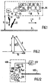
- the reference 1 indicates the device, object of the invention, for measuring the scrolling speed V.
- the device 1 which moves relative to the surface 2.
- the altitude with respect to soil 2 has the value "h”. This value is determined by means which will be explained later.
- the device 1 firstly comprises a transmitter circuit 10 associated with an antenna 11 for transmitting to the ground surface 2, a wave 12; this wave is reflected by the ground which generally behaves like a diffusing surface. This wave is picked up by the receiving antenna 23 and is then suitably processed by the receiving circuit 25 to undergo a frequency change and be amplified.
- the processing circuit 30 which follows, provides on a terminal 35 the indication of the speed V.
- the receiving circuit is associated with a single antenna (the antenna 23), the processing circuit 30 is provided with two branches, a so-called direct branch bearing the reference 50 intended to apply the reception signal available at the output. from the receiver circuit 25 to a multiplier 52; a second branch called the delaying branch bearing the reference 54 is intended to apply this same reception signal to the other input of the multiplier 52, after having brought a delay t o counted with respect to the direct branch.
- a frequency estimation device 60 At the output of the multiplication device 52 is provided at the output of the multiplication device 52 and finally a calculation device 62 for supplying the speed indication from the output signal from the estimation device 60 and altitude "h"; the transmitter circuit 10 is constituted by a fixed frequency oscillator.
- the invention is based on the following considerations:
- point D represents the location of the device located at a height "h" perpendicular to a point H on the surface 2.
- This point is located at a distance "d” from D.
- the wave emitted E (t) at point D has frequency f o and can be written:
- Figure 3 clearly shows the contradictory requirements imposed on the value t 0 .
- t o too high we can no longer see the same point and there is no longer a correlation between the signals at the output of branches 50 and 54.
- the values to be chosen for t o will be discussed later in this memo.
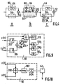
- Figure 4 shows the different ways of making the branches 50 and 54.
- the branch 54 is constituted by a delay line 80 bringing the delay t o required while the branch 50 is constituted by a direct connection.
- the spectra of the signals are fairly wide in frequency and we want to avoid the appearance of spurious signals due to untimely beats of the different components of the spectrum, these beats being provided in particular by the non-linearities of the organ 52, we dissociates the spectrum of the signals of the retarding branch 54 from that of the signals of the direct branch 50.
- a modulator 82 is used which cooperates with a displacement oscillator 84 inserted either in the retarding branch 54 as shown in b at the 4, either in the direct branch as shown in c of this same figure 4.
- Quadrature signals allow better processing to determine ⁇ .
- the signals z (t) and z ⁇ (t) can be worked out in a different way as shown in figure 6.
- a frequency estimation member 60 suitable for the invention. It consists first of all of a Fourier transformer 110 which supplies on its different outputs S1, S2, ... Sn signals representing the frequency components of the signal z (t). These component signals are accumulated in the accumulators 112 1 , 112 2 , ..., 112 " which supply a sum signal of a number of component signals recently developed by the transformer 110.
- a set of comparators 120 compares two two the output signals from the accumulators 112.
- a logic circuit 122 on the basis of the information supplied by the assembly 120, provides a closing signal for one of the switches 125 1 , 125 2 , ..., 125 " .
- the output signal of this divider circuit is applied to the transformer 110 and to the filters 130 1 , 130 2 , ..., 130 n .
- FIG. 10 Another way of processing the signals z (t) and z 1 ⁇ (t) is shown in FIG. 10.
- a divider 300 dividing the signal z ⁇ (t) by the signal z (t) provides a signal of form tg ( ⁇ t + ⁇ ) so that an Arctg 302 computer provides an indication of the frequency ⁇ .
- the last results provided by the computer 302 are accumulated by the accumulator 304.
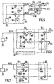
- FIG. 11 shows a device in accordance with the invention in which a pre-filter circuit 400 is also provided, arranged upstream of the frequency estimation member 60.
- the presence of this pre-filter circuit also requires a network of direct and retarding branches 402 connected to its output.
- the input of this prefilter circuit is connected to the output of the receiver circuit 25. It consists of a series of "m" bandpass filters 405 1 , 405 2 , 405 3 , ..., 405 m for respective frequencies F 1 , F 2 , F 3 , ..., F m .
- the inputs of all these filters are connected to the output of a mixer circuit 410 with two inputs, one of which is connected to the output of the receiver circuit 25 and the other to the output 0 of a voltage-controlled oscillator 412.
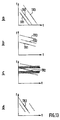
- this prefiltration circuit 400 To explain the operation of this prefiltration circuit 400, reference is made to FIG. 13; on this FIG. 13 from a to d the signals have been represented in a frequency-time space of the same type as that shown in a in FIG. 3.
- the line TR2 makes a contribution to determine ⁇ , that is to say that the other lines relate to other signals which do not evolve in the same way as the signal corresponding to TR2.
- the line TR2 for example could be horizontal if the speed V is perfectly estimated or does not change between the instant when the value ⁇ is determined by the member 60 and the instant when the signal corresponding to TR2 is received.
- the other signals defined by TR1 and TR3 will not be transmitted by this filter, just as 405 3 will only transmit TR2 because the frequencies TR1, TR2, TR3 ... are sufficiently spaced. This is shown in c in Figure 13 for TR2. Then the reference d in FIG. 13 indicates that for example only the signal defined by TR2 will come out of 405 2 , the others having therefore been eliminated.
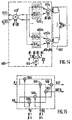
- the mixer circuits 410 ', 415' 1 , 415 ' m corresponding to the mixers 410, 415 1 , ..., 415 m' , have a structure which is shown in FIG. 14.
- the filters 405 ' 1 ,. .., 405 ' m are split so as to be able to filter the two signals available at the output of the mixer circuit 410'.
- the branch networks at the outputs of the mixing circuits can provide branches 50 and 54 shown in FIG. 5 for example.
- Oscillator 412 provides signals ⁇ 1, ⁇ 2, 03, 04 phase shifted by 0 °, 90 °, 180 ° and 270 ° respectively. Signals ⁇ 1 and ⁇ 2 are applied to the mixer circuit 410 'and signals ⁇ 3 and ⁇ 4 to the mixer circuits 415' 1 , ..., 415 ' m .
- the output OUT is constituted by the output of a subtraction member 500 and the output OUTQ by the output of a summation member 502.
- a first input of the member 500 is connected to the output of an elementary mixer circuit 504 and a second input of this same member 500 is connected to the output of a second elementary mixer circuit 506.
- a first input of the member 502 is connected to the output of a third elementary mixer circuit 508, another input to the output of a fourth mixer circuit 510.
- Input B is connected to an input of mixer circuits 504 and 508, input BQ to an input of mixer circuits 506 and 510.
- Input A is connected to the other input mixer circuits 504 and 510 and the AQ input to the other input of the mixer circuits 506 and 508.
- a device according to the invention shown in FIG. 16 includes means for giving a value to "h".
- these means consist of a radio altimeter of a type with linear frequency modulation; we can consult on this subject the French patent N ° 1 557 670.
- This radio altimeter comprises an emission part formed by an oscillator 600 linearly modulated in frequency by a sawtooth signal generator 602.
- a coupling circuit 604 allows the antenna 11 for simultaneously transmitting the signals supplied by the generator 10 and the oscillator 600.
- the reception part 610 of the radio altimeter is connected to the output of a coupling circuit 615; this allows the same antenna 23 to be used for the speed measuring device and for the radio altimeter.
- the value "h" established by the reception part 610 makes it possible to define the speed V according to the formula (4).
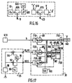
- FIG. 17 shows the preferred embodiment of the invention.
- the receiver circuit 25 which supplies the signals R (t) and R ⁇ (t) and the reception part 610 of a radio altimeter as described for FIG. 16 and which supplies the value "h” in analog form. numeric where as described in the aforementioned patent this value "h” can also be presented in numerical form.
- the signals h, R (t) and R ⁇ (t) are applied to the processing circuit 30 constituted from a microprocessor assembly 700.
- This assembly is formed in the most conventional manner by a microprocessor (for example the TMS 320 manufactured by TEXAS INSTRUMENT), a random access memory and a ROM memory to contain the instructions which govern the operation of the microprocessor and also to contain various constants useful for this operation.
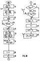
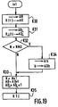
- FIGS. 18 and 19 show how the program contained in the ROM memory of the assembly 700 is produced.
- the different complex multiplication results are then stored in memory, preferably at the locations indicated by AD and AD ⁇ , increased by a value such that the results of the multiplication are not a substitute for samples already stored.
- box K10 the content of the value F MAX is tested: if it is zero, which corresponds to the first frequency determination, the value F MAX will take the value "fj" box K11; if the value F MAX is not zero, we test (box K12) if the value "f j " is compatible with the value measured previously, that is to say, we make, as indicated, the difference between these two values and we test it against a tolerance value s. If the test indicated in box K12 is negative, we go to the program connection "et1". If the same test is positive we go to box K11. In box K13 the value V is calculated according to the formula (4) already indicated, then this value is displayed (box K14) on the display 740.
- the Fourier transform is a 1024 bit transformer.
Landscapes
- Engineering & Computer Science (AREA)
- Radar, Positioning & Navigation (AREA)
- Remote Sensing (AREA)
- Computer Networks & Wireless Communication (AREA)
- Physics & Mathematics (AREA)
- General Physics & Mathematics (AREA)
- Radar Systems Or Details Thereof (AREA)
Claims (12)
Applications Claiming Priority (2)
| Application Number | Priority Date | Filing Date | Title |
|---|---|---|---|
| FR8504823A FR2579760B1 (fr) | 1985-03-29 | 1985-03-29 | Dispositif pour mesurer la vitesse de defilement d'une surface |
| FR8504823 | 1985-03-29 |
Publications (2)
| Publication Number | Publication Date |
|---|---|
| EP0201946A1 EP0201946A1 (de) | 1986-11-20 |
| EP0201946B1 true EP0201946B1 (de) | 1991-01-09 |
Family
ID=9317759
Family Applications (1)
| Application Number | Title | Priority Date | Filing Date |
|---|---|---|---|
| EP86200476A Expired - Lifetime EP0201946B1 (de) | 1985-03-29 | 1986-03-21 | Anordnung zur Messung des Geschwindigkeitsverlaufs einer Fläche |
Country Status (5)
| Country | Link |
|---|---|
| US (1) | US4706092A (de) |
| EP (1) | EP0201946B1 (de) |
| JP (1) | JPS61226671A (de) |
| DE (1) | DE3676739D1 (de) |
| FR (1) | FR2579760B1 (de) |
Families Citing this family (4)
| Publication number | Priority date | Publication date | Assignee | Title |
|---|---|---|---|---|
| US4758839A (en) * | 1987-07-22 | 1988-07-19 | Mcdonnell Douglas Corporation | Terrain profile radar system |
| US5047779A (en) * | 1990-08-28 | 1991-09-10 | Honeywell Inc. | Aircraft radar altimeter with multiple target tracking capability |
| JP2841028B2 (ja) * | 1994-11-25 | 1998-12-24 | ソニー株式会社 | 角速度検出装置 |
| US10006991B2 (en) * | 2015-02-11 | 2018-06-26 | Honeywell International Inc. | Velocity and attitude estimation using an interferometric radar altimeter |
Family Cites Families (6)
| Publication number | Priority date | Publication date | Assignee | Title |
|---|---|---|---|---|
| US2406358A (en) * | 1944-03-21 | 1946-08-27 | Bell Telephone Labor Inc | Ground speed meter |
| FR1557670A (de) * | 1967-09-11 | 1969-02-21 | ||
| US3594793A (en) * | 1968-07-25 | 1971-07-20 | King Radio Corp | Method and apparatus for determining the rate of change of a time interval |
| FR2443070A1 (fr) * | 1978-12-01 | 1980-06-27 | Trt Telecom Radio Electr | Dispositif de radar destine a fournir des informations de distance et de vitesse concernant une cible se deplacant par rapport a lui |
| FR2477283A1 (fr) * | 1980-03-03 | 1981-09-04 | Trt Telecom Radio Electr | Dispositif de radar destine notamment a mesurer par rapport a lui la vitesse v d'un objet |
| FR2502340A1 (fr) * | 1981-03-18 | 1982-09-24 | Trt Telecom Radio Electr | Dispositif de radar destine notamment a mesurer par rapport a lui la vitesse v d'un objet |
-
1985
- 1985-03-29 FR FR8504823A patent/FR2579760B1/fr not_active Expired
-
1986
- 1986-03-06 US US06/836,918 patent/US4706092A/en not_active Expired - Fee Related
- 1986-03-21 DE DE8686200476T patent/DE3676739D1/de not_active Expired - Lifetime
- 1986-03-21 EP EP86200476A patent/EP0201946B1/de not_active Expired - Lifetime
- 1986-03-29 JP JP61072401A patent/JPS61226671A/ja active Pending
Also Published As
| Publication number | Publication date |
|---|---|
| US4706092A (en) | 1987-11-10 |
| DE3676739D1 (de) | 1991-02-14 |
| JPS61226671A (ja) | 1986-10-08 |
| EP0201946A1 (de) | 1986-11-20 |
| FR2579760B1 (fr) | 1987-05-15 |
| FR2579760A1 (fr) | 1986-10-03 |
Similar Documents
| Publication | Publication Date | Title |
|---|---|---|
| US8204707B2 (en) | Time delay estimation | |
| EP0120775B1 (de) | Entfernungs- und Dopplermessung mittels einer Laseranordnung mit Pulszeitraffung | |
| EP0732803A1 (de) | Verfahren und Vorrichtung zum Demodulieren durch Abtastung | |
| EP0451232B1 (de) | Kodeerfassungsverfahren und schaltung für spreizspektrumsignalempfänger | |
| FR2739695A1 (fr) | Recepteur large bande a mesure de distance par signaux de code pseudo-aleatoire | |
| FR2626120A1 (fr) | Generateur d'impulsions en correlation | |
| FR2770700A1 (fr) | Dispositif et procede pour synchroniser des oscillateurs dans un systeme de communication de donnees | |
| EP0561690B1 (de) | Verfahren und Vorrichtung zur Feststellung des Erreichens eines vorausbestimmten Abstandes eines Punktreflektors mittels der Laufzeit einer kontinuierlichen Welle | |
| FR2566921A1 (fr) | Radioaltimetre a modulation de frequence | |
| EP0201946B1 (de) | Anordnung zur Messung des Geschwindigkeitsverlaufs einer Fläche | |
| FR2556845A1 (fr) | Procede de caracterisation par ondes acoustiques de la structure d'un milieu et dispositif mettant en oeuvre ce procede | |
| FR2633725A1 (fr) | Systeme radar radioaltimetrique a onde continue modulee en frequence | |
| EP0312180A1 (de) | Gerät zur Messung der Entfernung zu einem Objekt | |
| EP0863408B1 (de) | Geräuschreduzierungsvorrichtung für Radarempfänger | |
| EP0147305B1 (de) | Anordnung zur Unterscheidung von Radarechos | |
| EP3671266B1 (de) | Verfahren zur entfernungsmessung mit angepasster fourier-transformation, und radarsystem zur umsetzung dieses verfahrens | |
| FR2766575A1 (fr) | Procede et dispositif operant par interpolation dans un spectre discret pour determiner des caracteristiques d'un signal et applications | |
| FR2519209A1 (fr) | Filtre a boucle numerique | |
| FR2659811A1 (fr) | Recepteur de radionavigation par satellite. | |
| EP0246135A1 (de) | Phasen- und Frequenzdetektor und seine Anwendung in einer Phasenregelschleife | |
| EP0055636B1 (de) | Abweichungsempfänger für Sekundärradar | |
| EP0012056B1 (de) | Abstands-Messvorrichtung und deren Verwendung bei einem Verfolgungsradar | |
| EP0169127B1 (de) | Frequenzmodulierter Radiohöhenmesser | |
| FR3101157A1 (fr) | Mesure de distance basée sur phase avec temps d’acquisition constant | |
| FR2502340A1 (fr) | Dispositif de radar destine notamment a mesurer par rapport a lui la vitesse v d'un objet |
Legal Events
| Date | Code | Title | Description |
|---|---|---|---|
| PUAI | Public reference made under article 153(3) epc to a published international application that has entered the european phase |
Free format text: ORIGINAL CODE: 0009012 |
|
| AK | Designated contracting states |
Kind code of ref document: A1 Designated state(s): DE FR GB IT SE |
|
| 17P | Request for examination filed |
Effective date: 19870508 |
|
| 17Q | First examination report despatched |
Effective date: 19890206 |
|
| GRAA | (expected) grant |
Free format text: ORIGINAL CODE: 0009210 |
|
| AK | Designated contracting states |
Kind code of ref document: B1 Designated state(s): DE FR GB IT SE |
|
| PG25 | Lapsed in a contracting state [announced via postgrant information from national office to epo] |
Ref country code: IT Free format text: LAPSE BECAUSE OF FAILURE TO SUBMIT A TRANSLATION OF THE DESCRIPTION OR TO PAY THE FEE WITHIN THE PRE;WARNING: LAPSES OF ITALIAN PATENTS WITH EFFECTIVE DATE BEFORE 2007 MAY HAVE OCCURRED AT ANY TIME BEFORE 2007. THE CORRECT EFFECTIVE DATE MAY BE DIFFERENT FROM THE ONE RECORDED.SCRIBED TIME-LIMIT Effective date: 19910109 |
|
| REF | Corresponds to: |
Ref document number: 3676739 Country of ref document: DE Date of ref document: 19910214 |
|
| GBT | Gb: translation of ep patent filed (gb section 77(6)(a)/1977) | ||
| PLBE | No opposition filed within time limit |
Free format text: ORIGINAL CODE: 0009261 |
|
| STAA | Information on the status of an ep patent application or granted ep patent |
Free format text: STATUS: NO OPPOSITION FILED WITHIN TIME LIMIT |
|
| 26N | No opposition filed | ||
| REG | Reference to a national code |
Ref country code: GB Ref legal event code: 732E |
|
| EAL | Se: european patent in force in sweden |
Ref document number: 86200476.9 |
|
| PGFP | Annual fee paid to national office [announced via postgrant information from national office to epo] |
Ref country code: GB Payment date: 19960219 Year of fee payment: 11 |
|
| PGFP | Annual fee paid to national office [announced via postgrant information from national office to epo] |
Ref country code: SE Payment date: 19960223 Year of fee payment: 11 |
|
| PG25 | Lapsed in a contracting state [announced via postgrant information from national office to epo] |
Ref country code: GB Effective date: 19970321 |
|
| PG25 | Lapsed in a contracting state [announced via postgrant information from national office to epo] |
Ref country code: SE Effective date: 19970322 |
|
| GBPC | Gb: european patent ceased through non-payment of renewal fee |
Effective date: 19970321 |
|
| EUG | Se: european patent has lapsed |
Ref document number: 86200476.9 |
|
| PGFP | Annual fee paid to national office [announced via postgrant information from national office to epo] |
Ref country code: DE Payment date: 20010214 Year of fee payment: 16 |
|
| PGFP | Annual fee paid to national office [announced via postgrant information from national office to epo] |
Ref country code: FR Payment date: 20010320 Year of fee payment: 16 |
|
| PG25 | Lapsed in a contracting state [announced via postgrant information from national office to epo] |
Ref country code: DE Free format text: LAPSE BECAUSE OF NON-PAYMENT OF DUE FEES Effective date: 20021001 |
|
| PG25 | Lapsed in a contracting state [announced via postgrant information from national office to epo] |
Ref country code: FR Free format text: LAPSE BECAUSE OF NON-PAYMENT OF DUE FEES Effective date: 20021129 |
|
| REG | Reference to a national code |
Ref country code: FR Ref legal event code: ST |