EP0201643A1 - Unterdrückung von seismischem Geräusch - Google Patents
Unterdrückung von seismischem Geräusch Download PDFInfo
- Publication number
- EP0201643A1 EP0201643A1 EP85306853A EP85306853A EP0201643A1 EP 0201643 A1 EP0201643 A1 EP 0201643A1 EP 85306853 A EP85306853 A EP 85306853A EP 85306853 A EP85306853 A EP 85306853A EP 0201643 A1 EP0201643 A1 EP 0201643A1
- Authority
- EP
- European Patent Office
- Prior art keywords
- traces
- common
- gathers
- seismic
- shot
- Prior art date
- Legal status (The legal status is an assumption and is not a legal conclusion. Google has not performed a legal analysis and makes no representation as to the accuracy of the status listed.)
- Granted
Links
- 230000001629 suppression Effects 0.000 title description 2
- 230000001427 coherent effect Effects 0.000 claims abstract description 22
- 238000000034 method Methods 0.000 claims description 13
- 238000011109 contamination Methods 0.000 claims description 6
- XLYOFNOQVPJJNP-UHFFFAOYSA-N water Substances O XLYOFNOQVPJJNP-UHFFFAOYSA-N 0.000 description 7
- 239000011159 matrix material Substances 0.000 description 6
- 230000006870 function Effects 0.000 description 3
- 230000008569 process Effects 0.000 description 3
- 230000000644 propagated effect Effects 0.000 description 3
- 230000008901 benefit Effects 0.000 description 2
- 230000000694 effects Effects 0.000 description 2
- 208000010228 Erectile Dysfunction Diseases 0.000 description 1
- 230000009286 beneficial effect Effects 0.000 description 1
- 230000005540 biological transmission Effects 0.000 description 1
- 230000000052 comparative effect Effects 0.000 description 1
- 238000010276 construction Methods 0.000 description 1
- 238000012937 correction Methods 0.000 description 1
- 230000002452 interceptive effect Effects 0.000 description 1
- 238000010606 normalization Methods 0.000 description 1
- 238000003672 processing method Methods 0.000 description 1
- 230000008439 repair process Effects 0.000 description 1
- 238000005070 sampling Methods 0.000 description 1
- 238000000926 separation method Methods 0.000 description 1
- 230000007480 spreading Effects 0.000 description 1
- 230000001960 triggered effect Effects 0.000 description 1
- 230000000007 visual effect Effects 0.000 description 1
Images


Classifications
-
- G—PHYSICS
- G01—MEASURING; TESTING
- G01V—GEOPHYSICS; GRAVITATIONAL MEASUREMENTS; DETECTING MASSES OR OBJECTS; TAGS
- G01V1/00—Seismology; Seismic or acoustic prospecting or detecting
- G01V1/28—Processing seismic data, e.g. for interpretation or for event detection
- G01V1/36—Effecting static or dynamic corrections on records, e.g. correcting spread; Correlating seismic signals; Eliminating effects of unwanted energy
-
- G—PHYSICS
- G01—MEASURING; TESTING
- G01V—GEOPHYSICS; GRAVITATIONAL MEASUREMENTS; DETECTING MASSES OR OBJECTS; TAGS
- G01V2210/00—Details of seismic processing or analysis
- G01V2210/30—Noise handling
- G01V2210/32—Noise reduction
Definitions
- This invention is concerned with suppressing extraneous noise from seismic recordings.
- it is concerned with suppressing signals due to shots generated by an independently operating seismic exploration crew.
- a seismic ship In marine seismic exploration, a seismic ship tows a streamer cable including a plurality of seismic receivers such as hydrophones through a body of water.
- the streamer cable is generally towed at a desired depth beneath the water surface, such as 10 meters.
- the streamer cables provide 96 or more data channels and may be three kilometers or more in length.
- an acoustic source is triggered to produce an impulse at spaced-apart intervals of 25 to 50 meters.
- the acoustic waves from the impulse travel downwardly into the earth beneath the water.
- the waves are reflected from various earth layers back to the water surface where they are sensed by the receivers, converted to electrical signals as a function of total travel time, and recorded for future processing.
- a similar course of events takes place during land surveying, except of course, land vehicles replace ships.
- the receivers used in seismic streamer cables are quite sensitive as well as being omnidirectional. Any sound that the receiver hydrophones hear is detected and recorded. Thus, the receivers respond not only to an impulse or "shot" generated by their own ship, but may also respond to shots generated or fired by another ship. For any given ship, shots from other ships are necessarily coherent noise interference but generated at time intervals unrelated to those of the impulses of the given ship.
- the energy level of the first, direct water-arrivals from a shot may be 80 to 120 dB higher than the much weaker reflected arrivals that arrive several seconds later.
- the water volume between the water surface and the sea floor acts as an acoustic wave guide. Because of that phenomenon, the first direct signal arrivals from a ship as far as 50 to 100 kilometers distant may create a serious noise problem for some other ship. The problem of other-ship noise contamination is so serious that the respective operators within a given.area allot daily time periods amongst themselves so that each operator can conduct his studies in comparative quiet.
- a marine seismic crew operates 24 hours per day to maximize revenue time against fixed overhead. Any involuntary standby time is very costly.
- a seismic ship successively generates seismic signals at a number of different shot locations along a line of survey.
- a spread of receivers towed behind the ship, receive the reflected seismic signals at successively different receiver locations along the line.
- the respective receiver locations for each shot have a constant offset with respect to the shot locations.
- the receivers convert the received seismic signals to electrical signals as time-scale traces to form a plurality of common shot gathers.
- the shot gathers are reformatted as common receiver gathers, thereby reordering traces having coherent noise from some other sound source.
- the traces of the common receiver gathers are grouped by adjacent pairs. One trace of each pair is corrected for differential normal moveout relative to the other trace of the pair.
- the two traces of each pair are weighted in inverse proportion to the power of the received seismic signals on each trace and then are combined, such as by summing and normalizing to create a compressed common receiver gather.
- the compressed common receiver gathers may be reformatted to a common midpoint gather.
- the step of trace-pair weighting is carried out over a running time window having a preselected length prior to the steps of combining and reformatting.
- the common receiver gathers are grouped as triplets, three traces per group. Differential normal moveout is then applied to two of the traces to correct them to the third trace. Thereafter, the steps of weighting and combining are carried out as before.
- FIG. 1 there is shown in plan view, a seismic ship 10, towing a streamer cable 12, to which are secured a plurality of seismic signal receivers R1-R6.
- a receiver array as shown is termed a receiver spread. Typically, the separation between receivers may be about 25 meters.
- the receivers sense seismic signals and convert the seismic signals to electrical signals which are transmitted by a transmission link in cable 12 to a data processor 15 in ship 10.
- the electrical signals are digitized at convenient sample intervals such as every 2 milliseconds (ms) and are stored for processing.
- Another ship 16 which may be many kilometers away, is also towing a seismic cable 17 and receivers such as rl-r4 and a sound source 18. At intervals, ship 16 also fires a shot.
- the direct water-borne seismic signals 20 may reach receivers R 1-R6 during ship 10's listening period to produce a coherent noise burst that interferes with desired signals. Since the operation of ship 16 is independent of the operations of ship 10, coherent noise contamination may occur at regular intervals unrelated to the operations of ship 10.
- FIG. 2 is a plan view of the progress of a continuous seismic profiling operation, beginning at one end of a line of survey. From Figure 1, we saw that the seismic cable 12 and receivers R1-R6 trail behind ship 10. At a shot location such as Sl the receivers, at receiver locations R1-R6 sense seismic signals over the surface coverage of the receiver spread represented by solid line 11. Observe that the receiver and shot spacings are equal. Customarily there is a gap between the shot location and the first receiver, of several receiver spacings. As ship 10 proceeds to the right along the line of survey to S2 the receiver spread trails along behind so that receivers Rl-R6 now occupy locations S1-R5 as shown by solid line 13.
- the receiver spread R1-R6 occupies surface locations S5-R1, solid line 19.
- a shot is fired and seismic reflection data are acquired at the corresponding receiver spread location.
- the significance of the dashed line coverage will be discussed later in connection with Figures 6 and 7.
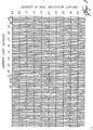
- Figure 3 is a synthetic seismic section of a series of seismic time-scale recordings that happen to have 12 traces per recording that correspond to a 12-receiver spread rather than the oversimplified 6-receiver spread in Figure 2.
- Each record constitutes a common shot gather that was shot and recorded from successively different shot locations, Sl-SlO, (analogous to Figure 2) and at different times during an operating day.
- Sl-SlO shot locations
- Each record exhibits three reflections having two-way travel times of 0.9, 2.25, and 3.85 seconds, referred to the rightmost trace of each section.
- the reflections of Figure 3 are uncorrected for normal moveout (NMO).
- NMO normal moveout
- S l a strong coherent noise burst 21, at 2.55 seconds, cuts across the record, interfering with the reflection at 2.25 seconds. That event is the coherent other-ship noise due to direct, water-borne seismic waves, symbolized as 20 in Figure 1. It is that noise that we wish to eliminate.
- Figure 4 represents schematically an elevational view of seismic-signal ray paths or signal travel paths associated with six successively different shot locations S1-S6 and receiver locations R1-R6.
- the shot and receiver locations are at or near the surface 22 of a body of water 23 as shown at the upper half of Figure 2, solid line 11.
- a sub-bottom earth-layer reflecting surface 24 is shown.
- a seismic signal propagates along a ray path Sl-Ma-Rl where it is sensed by Rl. Since the signal propagates by spherical spreading from Sl, many other ray paths Sl-Mb-R2 to Sl-Mf-R6 are possible.
- the respective Ms are the ray-path midpoints which, for a 25-meter receiver spacing, are necessarily 12.5 meters apart.
- Each receiver provides a single time-scale trace on a seismic record as in Figure 3. As before stated, such a record is said to constitute a common shot gather associated with the bundle of raypaths 28. Other common shot gathers may be constructed for each of the other shot locations S2 to S6, of which only the common shot gather 30 is shown to avoid confusing the drawing.
- NMO 3 is a hyperbolic function proportional to the square of the offset (distance between shot and receiver) and inversely proportional to vertical travel time. The effect of NMO can be seen from the hyperbolic curvature of the respective reflections on the records of Figure 3. Differential NMO is simply the difference in travel time between any two ray paths.
- Midpoint Ma is common to ray-paths Sl-Ma-Rl, S6-Ma-R6, and SO-Ma-RO. If the travel times along the two oblique paths are corrected for NMO, they become equal to the vertical travel time SO-Ma-RO.
- the resulting three corrected seismic traces can now be summed to produce a three-fold common midpoint (CMP) stack or gather.
- CMP gather is quite effective in cancelling random incoherent noise but it is ineffective in cancelling coherent noise. That effect is shown in Figure 5.
- the traces of each record of Figure 5 have been compressed to a six-fold CMP stack. Although most of the traces are clean, the traces involving record Sl are severely contaminated with noise.
- each receiver senses seismic signals from several different shot locations. For example, Rl receives signals from the successively different shot locations S1-S6 and at successively different points in time. Therefore, it is possible to reformat the common shot gathers to a common receiver gather for R l as indicated by ray-path bundle 32. Similarly we can produce a common receiver-trace gather 34 for R2, Figure 7.
- the distance or offset between R l and S6 is the same as the offset between R2 and S5.
- the process of interchanging shot location and receiver location is valid because of the well-known reciprocity principle. That is, the signal travel path from Sl to Rl, for example is exactly the same as the travel path from Rl to Sl.
- the dashed lines represent the common receiver gathers that were derived from the common shot gathers shown by the solid lines at the upper portion of Figure 2.
- common receiver gather Rl is represented by the surface coverage of dashed line 31, Figure 2 and ray paths 32 of Figure 6.
- Common receiver gather R2 includes the surface coverage of dashed line 33, Figure 2 and ray paths 34 of Figure 7.
- the construction of common receiver gathers continues to R 6, dashed line 35, covering shots made at locations R5-S1.
- Figure 8 illustrates the common shot gathers of Figure 3 reformatted as common receiver gathers R1-R12.
- the coherent noise that contaminated the entire recording of common shot gather Sl has now been redistributed to appear only on one trace of each common receiver gather.
- the noise appears on trace 1, the rightmost trace, which corresponds to the first trace of Sl.
- the noise appears on trace 2 which corresponds to trace 2 of Sl (see also Figures 2, 6, 7).
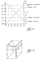
- the step of reformatting is most easily carried out by use of an addressable memory matrix.
- the extent of the matrix in Figure 9 is limited to a 6x6 array for purposes of example. In practice the extent of the matrix would be expanded to include all possible shot/receiver combinations as required to accommodate the required number of shot locations along the line and receivers along the spread. Refer to Figure 9. For any given signal travel-time increment, the shot locations are addressed by rows and the receivers associated with any shot location are addressed by columns. Thus for a common shot gather from S6 the signal samples sensed by receivers Rl-R6 are stored in memory cells along column S6 as shown by dashed line 40. Common receiver gathers may be constructed by extracting data samples along a row.
- a common receiver gather for R2 is constructed by extracting data samples from cells along dashed line 42.
- the data may be reformatted as a CMP gather by extracting data samples from cells lying along any diagonal line parallel to dashed line 44.
- a data sample that propagated from Sl to Rl has the same ray-path midpoint Ma as a data sample that propagated from S6 to R6 (refer back to Figure 4).
- a diagonal line such as 46 identifies those data samples that propagated along ray paths that have a common shot/receiver offset.
- the matrix of Figure 9 is two dimensional. Because seismic traces are time-scale recordings, a time axis T, mutually orthogonal to the Si and Rj axes must be added as in Figure 10.
- the time axis T may be expressed in terms of incremental sample counts for any given signal-sampling rate. It is convenient to process seismic signals within 5 a time window such as t 2 -t l where the length of the window may be on the order of 150 to 200 ms or 75 to 100 samples at a 2-ms sample rate.
- the traces are grouped by adjacent pairs. For example, referring to Figure 6, traces corresponding to ray paths Rl-Ma-Sl and Rl-Mg-S2 form one adjacent-trace pair, Rl-Mh-S3 and Rl-Mi-54 form another adjacent-trace pair, and similarly for the other traces.
- One trace of each pair is then corrected for differential NMO so that the two traces later can be summed.
- the differential NMO need be only an estimate of the true value.
- the traces could be grouped by triplets with the estimated differential NMO being applied to two of the traces to correct them to the third trace. For deeper portions of a time-scale recording the differential moveout becomes very small so that differential NMO may be elimated.
- the two traces of each pair are weighted in inverse proportion to the RMS signal power level. Any one of a number of known statistical weighting schemes may be used. For example, let wnere P(t) is the signal power level at time t, A i (t) is the signal amplitude level at each sample time t i , and n is the number of samples embraced within a selected time window t 2 - t l .
- the time-window length is chosen to bracket the coherent noise bursts as seen on the original common shot-trace gather.
- the time window length would be about 200 ms.
- the weighting factor O(t) is defined over a running time window. That is, successive output-trace weighting factors are determined for successive data samples from a running average of the data samples within that time window t 2 - t 1 that is centered around the data sample t i under consideration.
- the two adjacent traces of each pair are combined, such as by summing and normalizing, to generate a set of twelve, 6-trace, common receiver gathers as shown in Figure 11, wherein the coherent noise has been successfully suppressed to a level so small as to be insignificant.
- the shallow reflections at 0.9 second have been muted on the leftmost three traces.
- the differential N MO is very large.
- Application of differential NMO severely distorts the waveform such that a valid summation is not possible.
- Adjacent-trace summing may be replaced by a running average of two or three traces provided suitable NMO corrections are made.
- the compressed common receiver gathers of Figure 11 are preferably reformatted and displayed as a visual CMP stacked, time-scale recording as in Figure 12, preparatory to further conventional data processing.
- the coherent-noise-suppressed CMP stack of Figure 12, derived from common receiver gathers may be contrasted with the CMP stack of Figure 5 that was derived from common shot gathers, to appreciate the beneficial results to be had from the practice of my invention.
- processing steps referred to above may be carried out by suitable purpose built digital processing units, or by a suitably programmed computer.
Landscapes
- Engineering & Computer Science (AREA)
- Remote Sensing (AREA)
- Physics & Mathematics (AREA)
- Life Sciences & Earth Sciences (AREA)
- Acoustics & Sound (AREA)
- Environmental & Geological Engineering (AREA)
- Geology (AREA)
- General Life Sciences & Earth Sciences (AREA)
- General Physics & Mathematics (AREA)
- Geophysics (AREA)
- Geophysics And Detection Of Objects (AREA)
- Radar Systems Or Details Thereof (AREA)
- Measurement Of Velocity Or Position Using Acoustic Or Ultrasonic Waves (AREA)
Applications Claiming Priority (2)
| Application Number | Priority Date | Filing Date | Title |
|---|---|---|---|
| US73115285A | 1985-05-06 | 1985-05-06 | |
| US731152 | 1985-05-06 |
Publications (2)
| Publication Number | Publication Date |
|---|---|
| EP0201643A1 true EP0201643A1 (de) | 1986-11-20 |
| EP0201643B1 EP0201643B1 (de) | 1989-12-06 |
Family
ID=24938282
Family Applications (1)
| Application Number | Title | Priority Date | Filing Date |
|---|---|---|---|
| EP85306853A Expired EP0201643B1 (de) | 1985-05-06 | 1985-09-26 | Unterdrückung von seismischem Geräusch |
Country Status (3)
| Country | Link |
|---|---|
| EP (1) | EP0201643B1 (de) |
| DE (1) | DE3574628D1 (de) |
| NO (1) | NO170441C (de) |
Cited By (7)
| Publication number | Priority date | Publication date | Assignee | Title |
|---|---|---|---|---|
| NL9000577A (nl) * | 1989-03-17 | 1990-10-16 | Geco As | Werkwijze in een systeem in werkelijke tijd voor het beheersen van seismische interferentie. |
| EP0681193A1 (de) * | 1994-05-05 | 1995-11-08 | Western Atlas International, Inc. | Verfahren zum Abschwächen von coherenten Lärm in marine seismischen Daten |
| US5818795A (en) * | 1996-10-30 | 1998-10-06 | Pgs Tensor, Inc. | Method of reduction of noise from seismic data traces |
| GB2424481A (en) * | 2005-03-23 | 2006-09-27 | Westerngeco Seismic Holdings | Reducing noise in seismic data |
| CN104375181A (zh) * | 2014-11-24 | 2015-02-25 | 中国石油天然气集团公司 | 一种快速生成三维共检波点初至道集的方法 |
| US10261202B2 (en) | 2014-10-22 | 2019-04-16 | Cgg Services Sas | Device and method for mitigating seismic survey interference |
| CN112255683A (zh) * | 2020-10-26 | 2021-01-22 | 中国石油天然气集团有限公司 | 地震资料的噪声压制方法及装置 |
Citations (2)
| Publication number | Priority date | Publication date | Assignee | Title |
|---|---|---|---|---|
| GB1208424A (en) * | 1967-10-20 | 1970-10-14 | Mobil Oil Corp | Optimum seismic velocity filters |
| US3638175A (en) * | 1970-03-10 | 1972-01-25 | Exxon Production Research Co | Noise reduction on seismic records |
-
1985
- 1985-07-10 NO NO852766A patent/NO170441C/no unknown
- 1985-09-26 EP EP85306853A patent/EP0201643B1/de not_active Expired
- 1985-09-26 DE DE8585306853T patent/DE3574628D1/de not_active Expired - Fee Related
Patent Citations (2)
| Publication number | Priority date | Publication date | Assignee | Title |
|---|---|---|---|---|
| GB1208424A (en) * | 1967-10-20 | 1970-10-14 | Mobil Oil Corp | Optimum seismic velocity filters |
| US3638175A (en) * | 1970-03-10 | 1972-01-25 | Exxon Production Research Co | Noise reduction on seismic records |
Cited By (12)
| Publication number | Priority date | Publication date | Assignee | Title |
|---|---|---|---|---|
| NL9000577A (nl) * | 1989-03-17 | 1990-10-16 | Geco As | Werkwijze in een systeem in werkelijke tijd voor het beheersen van seismische interferentie. |
| US5014249A (en) * | 1989-03-17 | 1991-05-07 | Geco A.S. | Method in a real time control system for seismic interference |
| EP0681193A1 (de) * | 1994-05-05 | 1995-11-08 | Western Atlas International, Inc. | Verfahren zum Abschwächen von coherenten Lärm in marine seismischen Daten |
| AU689221B2 (en) * | 1994-05-05 | 1998-03-26 | Schlumberger Seismic Holdings Limited | Method for attenuating coherent noise in marine seismic data |
| US5818795A (en) * | 1996-10-30 | 1998-10-06 | Pgs Tensor, Inc. | Method of reduction of noise from seismic data traces |
| GB2424481A (en) * | 2005-03-23 | 2006-09-27 | Westerngeco Seismic Holdings | Reducing noise in seismic data |
| US7328109B2 (en) | 2005-03-23 | 2008-02-05 | Westerngeco L.L.C. | Processing seismic data |
| GB2424481B (en) * | 2005-03-23 | 2008-06-04 | Westerngeco Seismic Holdings | Processing seismic data |
| US10261202B2 (en) | 2014-10-22 | 2019-04-16 | Cgg Services Sas | Device and method for mitigating seismic survey interference |
| CN104375181A (zh) * | 2014-11-24 | 2015-02-25 | 中国石油天然气集团公司 | 一种快速生成三维共检波点初至道集的方法 |
| CN112255683A (zh) * | 2020-10-26 | 2021-01-22 | 中国石油天然气集团有限公司 | 地震资料的噪声压制方法及装置 |
| CN112255683B (zh) * | 2020-10-26 | 2024-07-26 | 中国石油天然气集团有限公司 | 地震资料的噪声压制方法及装置 |
Also Published As
| Publication number | Publication date |
|---|---|
| NO170441C (no) | 1992-10-14 |
| EP0201643B1 (de) | 1989-12-06 |
| NO852766L (no) | 1986-11-06 |
| DE3574628D1 (de) | 1990-01-11 |
| NO170441B (no) | 1992-07-06 |
Similar Documents
| Publication | Publication Date | Title |
|---|---|---|
| US4937794A (en) | Seismic noise suppression method | |
| US5973995A (en) | Method of and apparatus for marine seismic surveying | |
| US4992992A (en) | Processing for seismic data from slanted cable | |
| US5524100A (en) | Method for deriving water bottom reflectivity in dual sensor seismic surveys | |
| US6161076A (en) | Seismic data acquisition and processing using non-linear distortion in a vibratory output signal | |
| US4254480A (en) | Frequency independent directionally sensitive array in seismic surveying | |
| US5621699A (en) | Apparatus and method of calibrating vertical particle velocity detector and pressure detector in a sea-floor cable with in-situ passive monitoring | |
| AU619493B2 (en) | Method and device for acquisition of seismic data | |
| EA001196B1 (ru) | Способ и устройство для повышения отношения кратности перекрытия к длине морской сейсмической косы | |
| GB2303705A (en) | Reducing noise in seismic signals | |
| US6961284B2 (en) | Source array for use in marine seismic exploration | |
| EP0527030B1 (de) | Verfahren vertikaler seismischer Messung | |
| GB2319611A (en) | Marine seismic surveying | |
| US4405999A (en) | Method for collecting and generating composite trace signals with improved signal to noise ratios | |
| EP0201643B1 (de) | Unterdrückung von seismischem Geräusch | |
| US6246637B1 (en) | Method and system for combining three component seismic data | |
| GB2346975A (en) | Processing seismic data | |
| EP0689064B1 (de) | Verfahren zur adaptiven Verminderung von Rauschtransienten in seismischen Signalen von Doppelsensoren | |
| EP0541265A2 (de) | Verfahren zur Verarbeitung seismischer Daten | |
| EP0869375B1 (de) | Beseitigung von Aliasing in der 3-D Kirchhoff DMO Operator | |
| Hutchinson et al. | Processing of Lake Baikal marine multichannel seismic reflection data | |
| Cullen et al. | P-wave seismograms from three seismic sources in SW USSR | |
| CA2206773C (en) | Method of and apparatus for marine seismic surveying | |
| Dragoset et al. | Data enhancement from a 500-channel streamer | |
| Trabant | Multifold Acquisition and Digital Processing |
Legal Events
| Date | Code | Title | Description |
|---|---|---|---|
| PUAI | Public reference made under article 153(3) epc to a published international application that has entered the european phase |
Free format text: ORIGINAL CODE: 0009012 |
|
| AK | Designated contracting states |
Kind code of ref document: A1 Designated state(s): BE DE FR GB NL SE |
|
| 17P | Request for examination filed |
Effective date: 19870507 |
|
| RAP1 | Party data changed (applicant data changed or rights of an application transferred) |
Owner name: WESTERN ATLAS INTERNATIONAL, INC. |
|
| 17Q | First examination report despatched |
Effective date: 19880729 |
|
| GRAA | (expected) grant |
Free format text: ORIGINAL CODE: 0009210 |
|
| AK | Designated contracting states |
Kind code of ref document: B1 Designated state(s): BE DE FR GB NL SE |
|
| REF | Corresponds to: |
Ref document number: 3574628 Country of ref document: DE Date of ref document: 19900111 |
|
| ET | Fr: translation filed | ||
| PLBE | No opposition filed within time limit |
Free format text: ORIGINAL CODE: 0009261 |
|
| STAA | Information on the status of an ep patent application or granted ep patent |
Free format text: STATUS: NO OPPOSITION FILED WITHIN TIME LIMIT |
|
| 26N | No opposition filed | ||
| EAL | Se: european patent in force in sweden |
Ref document number: 85306853.4 |
|
| PGFP | Annual fee paid to national office [announced via postgrant information from national office to epo] |
Ref country code: SE Payment date: 19980820 Year of fee payment: 14 Ref country code: FR Payment date: 19980820 Year of fee payment: 14 |
|
| PGFP | Annual fee paid to national office [announced via postgrant information from national office to epo] |
Ref country code: NL Payment date: 19980825 Year of fee payment: 14 |
|
| PGFP | Annual fee paid to national office [announced via postgrant information from national office to epo] |
Ref country code: GB Payment date: 19980826 Year of fee payment: 14 Ref country code: DE Payment date: 19980826 Year of fee payment: 14 |
|
| PGFP | Annual fee paid to national office [announced via postgrant information from national office to epo] |
Ref country code: BE Payment date: 19980914 Year of fee payment: 14 |
|
| PG25 | Lapsed in a contracting state [announced via postgrant information from national office to epo] |
Ref country code: GB Free format text: LAPSE BECAUSE OF NON-PAYMENT OF DUE FEES Effective date: 19990926 |
|
| PG25 | Lapsed in a contracting state [announced via postgrant information from national office to epo] |
Ref country code: SE Free format text: THE PATENT HAS BEEN ANNULLED BY A DECISION OF A NATIONAL AUTHORITY Effective date: 19990929 |
|
| PG25 | Lapsed in a contracting state [announced via postgrant information from national office to epo] |
Ref country code: BE Free format text: LAPSE BECAUSE OF NON-PAYMENT OF DUE FEES Effective date: 19990930 |
|
| BERE | Be: lapsed |
Owner name: WESTERN ATLAS INTERNATIONAL INC. Effective date: 19990930 |
|
| PG25 | Lapsed in a contracting state [announced via postgrant information from national office to epo] |
Ref country code: NL Free format text: LAPSE BECAUSE OF NON-PAYMENT OF DUE FEES Effective date: 20000401 |
|
| EUG | Se: european patent has lapsed |
Ref document number: 85306853.4 |
|
| GBPC | Gb: european patent ceased through non-payment of renewal fee |
Effective date: 19990926 |
|
| PG25 | Lapsed in a contracting state [announced via postgrant information from national office to epo] |
Ref country code: FR Free format text: LAPSE BECAUSE OF NON-PAYMENT OF DUE FEES Effective date: 20000531 |
|
| NLV4 | Nl: lapsed or anulled due to non-payment of the annual fee |
Effective date: 20000401 |
|
| PG25 | Lapsed in a contracting state [announced via postgrant information from national office to epo] |
Ref country code: DE Free format text: LAPSE BECAUSE OF NON-PAYMENT OF DUE FEES Effective date: 20000701 |
|
| REG | Reference to a national code |
Ref country code: FR Ref legal event code: ST |