EP0201624A2 - Ballast circuit for a fluorescent lamp - Google Patents
Ballast circuit for a fluorescent lamp Download PDFInfo
- Publication number
- EP0201624A2 EP0201624A2 EP85111393A EP85111393A EP0201624A2 EP 0201624 A2 EP0201624 A2 EP 0201624A2 EP 85111393 A EP85111393 A EP 85111393A EP 85111393 A EP85111393 A EP 85111393A EP 0201624 A2 EP0201624 A2 EP 0201624A2
- Authority
- EP
- European Patent Office
- Prior art keywords
- fluorescent lamp
- current
- signal
- ballast according
- lamp
- Prior art date
- Legal status (The legal status is an assumption and is not a legal conclusion. Google has not performed a legal analysis and makes no representation as to the accuracy of the status listed.)
- Withdrawn
Links
Images

Classifications
-
- H—ELECTRICITY
- H05—ELECTRIC TECHNIQUES NOT OTHERWISE PROVIDED FOR
- H05B—ELECTRIC HEATING; ELECTRIC LIGHT SOURCES NOT OTHERWISE PROVIDED FOR; CIRCUIT ARRANGEMENTS FOR ELECTRIC LIGHT SOURCES, IN GENERAL
- H05B41/00—Circuit arrangements or apparatus for igniting or operating discharge lamps
- H05B41/14—Circuit arrangements
- H05B41/36—Controlling
- H05B41/38—Controlling the intensity of light
- H05B41/39—Controlling the intensity of light continuously
- H05B41/392—Controlling the intensity of light continuously using semiconductor devices, e.g. thyristor
-
- H—ELECTRICITY
- H05—ELECTRIC TECHNIQUES NOT OTHERWISE PROVIDED FOR
- H05B—ELECTRIC HEATING; ELECTRIC LIGHT SOURCES NOT OTHERWISE PROVIDED FOR; CIRCUIT ARRANGEMENTS FOR ELECTRIC LIGHT SOURCES, IN GENERAL
- H05B41/00—Circuit arrangements or apparatus for igniting or operating discharge lamps
- H05B41/14—Circuit arrangements
- H05B41/26—Circuit arrangements in which the lamp is fed by power derived from dc by means of a converter, e.g. by high-voltage dc
- H05B41/28—Circuit arrangements in which the lamp is fed by power derived from dc by means of a converter, e.g. by high-voltage dc using static converters
- H05B41/295—Circuit arrangements in which the lamp is fed by power derived from dc by means of a converter, e.g. by high-voltage dc using static converters with semiconductor devices and specially adapted for lamps with preheating electrodes, e.g. for fluorescent lamps
- H05B41/298—Arrangements for protecting lamps or circuits against abnormal operating conditions
- H05B41/2988—Arrangements for protecting lamps or circuits against abnormal operating conditions for protecting the lamp against abnormal operating conditions
Definitions
- the invention relates to a fluorescent lamp ballast with a power supply circuit that feeds two parallel circuit branches, each of which leads via an electrode of the fluorescent lamp and contains two electronic switches in series, a control unit for controlling the electronic switch, an inductor for generating the ignition voltage for the fluorescent lamp and a current sensor.
- the usual electronic fluorescent lamp ballasts contain a series resonant circuit that is triggered by an inverter and generates an oscillation whose frequency is above the hearing range of the human ear.
- the fluorescent lamp is connected in parallel to the capacitor of the series resonant circuit.
- Such ballasts have the Disadvantage that the fluorescent lamp is operated at a relatively high frequency and causes high-frequency electromagnetic interference. At the high frequency, parasitic line capacitances become effective, so that in order to achieve reproducible properties, a defined line routing from the device to the fluorescent lamps is required. Difficulties arise particularly when the fluorescent lamp is removed from the socket or when its resistance has become too great due to aging.
- ballasts mentioned require additional safety circuits to ensure that operation only takes place when a fluorescent lamp used is functioning properly.
- the known ballasts are each designed only for a narrow power range of the fluorescent lamp and for a very limited range of supply voltages. Different ballasts must be used for different lamp powers, lamp voltages and supply voltages.
- the fluorescent lamp is supplied with a high-frequency voltage, the lamp current depending on various parameters, for example the lamp resistance.
- the lamp resistance depending on various parameters, for example the lamp resistance.
- the invention has for its object to provide a fluorescent lamp ballast of the type mentioned, which can be used equally for lamps with different lamp powers and different lamp voltages.
- the current sensor and the inductor are connected in series with the two circuit branches and that the current sensor controls a switching element which is also connected in series in such a way that this switching element opens the circuit when the current has a specific value exceeds the first threshold and closes the circuit when the current falls below a certain second threshold that is lower than the first threshold.
- the current drawn by the circuit branches current ie the L ampenstrom constantly remains in the range between the first and the second threshold value and is thus kept almost constant.
- a defined current is therefore supplied to the lamp, which is independent of the level of the externally applied voltage and also independent of the lamp resistance.
- the lamp current is kept almost lossless because the switching element is either in the on state or in the off state in each phase.
- the switching element is in the on state, the current through the inductance in the lamp circuit increases slowly until the first threshold value is reached. The switching element is then blocked so that the inductance discharges and the current slowly drops to the second threshold value.
- the inductance which ensures a slow increase and slow decrease in the lamp current within the bandwidth specified by the two threshold values, can simultaneously be used to generate the high voltage required to ignite the fluorescent lamp.
- the threshold values can be changed individually or together depending on at least one control signal.
- the ballast can, for example, perform a dimmer function if the threshold values are changed by a control signal which can be influenced manually. If the thresholds are high, the lamp current is high and the lamp is bright; If the threshold values are lowered, the lamp current becomes smaller and the lamp shines less brightly.
- To regulate threshold values automatically for example depending on the illuminance prevailing in the room in which the fluorescent lamp is located or depending on the lamp temperature.
- the ballast can be supplied with different supply voltages, for example with a mains voltage of 110 V and a frequency of 60 Hz or with a mains voltage of 220 V and 50 Hz. Since the lamp current is kept constant regardless of the supply voltage , the ballast works with different supply voltages without switching.
- the two threshold voltages can preferably be changed together, so that the bandwidth of the current fluctuations does not change when the current amplitude changes.
- the electronic switches are controlled in such a way that the fluorescent lamp is reversed with a frequency below 100 Hz.
- the polarity reversal frequency should be below 1 Hz and preferably below 1 mHz.
- the fluorescent lamp is operated to a certain extent with direct current, with a polarity reversal taking place at relatively large time intervals.
- the polarity reversal is necessary to prevent cataphoresis in the fluorescent lamp. Cataphoresis occurs when the lamp is operated with the same polarity for a long time. It is a mercury displacement for a K-Thode out, which can be dismantled by reversing the polarity of the lamp.
- the polarity reversal can take place at relatively large intervals of, for example, one hour. This would correspond to a pole reversal frequency of approx. 0.3 mHz. While the usual ballasts with one above the According to the invention, the polarity reversal frequency of the lamp is made low. The lamp current is kept constant in every half period, the switchover is only from time to time to avoid cataphoresis.
- An integration device is preferably provided which forms the time integral over this current during each period of the current flowing through the fluorescent lamp and initiates the next period when this integral has become zero.
- the polarity reversal of the fluorescent lamp does not necessarily take place with a constant half-period.
- the lamp current in the second half-period may differ from that in the first half-period, e.g. if the lamp current has been changed by dimming.
- the time integral is formed over the current in each of the half-periods, and when the integrals of the positive and negative half-periods are equal to one another, the period is ended.
- the integral formation takes place, particularly in the case of long half-periods, preferably by converting the current values into digital form and adding them up cumulatively.
- ballast Since the current is regulated in the ballast according to the invention, there are numerous possibilities for influencing this current in order to achieve different operating states of the fluorescent lamp.
- a particular advantage is that the ballast can be used without structural changes for fluorescent lamps with different powers by the size of the lamp current according to the lamp power is set. This setting can be made either on a manually adjustable signal transmitter or depending on the parameters of the fluorescent lamp used in the ballast. In the latter case, the lamp current required by the fluorescent lamp in question is set automatically.
- the ballast according to the invention also enables the use of a dimmer circuit with which the lamp current is changed as a function of an external control signal.
- This control signal can be generated either by manually adjusting the dimmer circuit or by an external sensor.
- a particular problem with fluorescent lamp ballasts is starting the fluorescent lamp. Before starting, the electrodes of the fluorescent lamp are preheated for a certain time with direct currents. Thereafter, several ignition attempts are made in succession in the known ballasts by interrupting both circuit branches which lead over the electrodes of the fluorescent lamp, ie by briefly blocking one of the electronic switches for the passage of current. The inductance then briefly supplies a high ignition voltage. According to a preferred embodiment of the invention, numerous short firing pulses are with short time A b stands supplied to one pair of diagonally arranged electronic switch to open and close periodically. The repetition frequency of the ignition pulses is so high that the charge carriers in the interior of the fluorescent lamp cannot essentially recombine between two ignition pulses. In this way, the ignition takes place after several ignition pulses.
- the ignitability of the Fluorescent lamp builds up like a staircase curve.
- a particular advantage is that the inductance required for ignition can be kept relatively small. This inductance is reduced by a factor of n compared to the usual ignition with individual pulses, where n represents the number of briefly successive ignition pulses.
- the smaller inductance not only reduces the required coil dimensions and iron weight, but also the stored energy.
- the electronic switches are not destroyed even in the event of voltage breakdowns, since the low energy stored in the coil is not sufficient for this.
- the electronic switch used for ignition is only held in the blocking state for as long as a reversible voltage breakdown occurs at this switch, but the switch is not destroyed. In the event of a voltage breakdown, the blocked electronic switch behaves like a zener diode.
- the second breakdown leading to destruction which is referred to as thermal breakdown, is avoided by the current limitation.
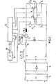
- the ballast shown in FIG. 1 has a rectifier circuit 10, which is fed with an alternating voltage via a low-pass filter 11 for eliminating interference voltages from or into the supply network.
- the rectifier circuit 10 generates a DC voltage on the capacitor C, which does not have to be regulated, and the level of which may depend on the applied mains voltage.
- the switching element T S which is a switching transistor, is connected to the positive pole of the supply voltage.
- the switching element T and the electronic switches to be described below are shown in the drawing as mechanical switches.
- the switching element T S is connected in series with the current sensor I and the inductance L.
- the parallel connection of the two circuit branches 12 and 13 is connected to this series connection.
- the other end of this parallel connection is connected to the negative pole of the rectifier 10.
- the circuit branch 12 contains the electronic switches T 1 and T 3 , between which the one electrode 14 1 the fluorescent lamp 14 is switched.
- the other circuit branch 13 contains the series connection of the transistors T 2 and T 4 , between which the second electrode 14 2 of the fluorescent lamp 14 is connected.
- the switches T 1 to T 4 are controlled by the logic control unit 15, which can be a microprocessor, for example.
- the comparator 16 generates two threshold values from the reference voltage, one of which corresponds to a maximum lamp current i L max and the other to a minimum lamp current i L min.
- the comparator 16 blocks the switching element T S , ie the series circuit is interrupted.
- the inductance L now tries to maintain the current that has previously flowed, so that the coil current i L slowly drops.
- this current reaches the lower limit value i Z min, the comparator 16 switches the switching element T S back into the conductive state, as a result of which the lamp current i L in the series circuit rises again.
- the electrodes 14 1 and 14 2 are first heated.
- all four switches T 1 to T 4 are controlled in the conductive state.
- two diagonally opposite switches, for example switches T 1 and T 4 are blocked.
- the current i L can be changed by appropriately controlling the comparator 16.
- the inductance L generates the voltage rise required for the ignition of the lamp 14.
- the lamp is now operated for a longer period of time, for example over an hour, using switches T 2 and T 3 , electrode 14 2 having a positive potential and electrode 14 1 having a negative potential.
- FIG. 3 shows the lamp current i L over time t, but the time scale is much larger than that of FIG. 2.
- the output signal of the current sensor I is integrated by the integrator 18. From Fig. 3 it can be seen that the integral f iL dt increases linearly with time. This integral is fed from the integrator 18 to the control unit 15. When the integral has reached a predetermined maximum value, the control unit 15 causes the switches T 1 and T 4 to be kept conductive and the switches T 2 and T 3 are subsequently blocked. The current then flows through T 1 , the lamps 14 and T 4 , so that the lamp 14 is reversed.
- the integrator 18 is reversed so that it is now integrated downwards.
- the upward and downward integration is controlled by the logic control unit 15 via the lines 19.
- the second half period 2HP is ended and the switches T 2 and T 3 become conductive again, and subsequently the switches T 1 and T 4 are blocked. It is thus achieved by the integrator 18 that the current integral in the first half period is equal to the current integral in the second half period. In this way, different current intensities, which may in the meantime be caused by the comparator 16, are taken into account, and it is achieved that the current applied to the lamp 14 is the same in both directions.
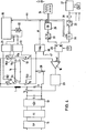
- FIGS. 4 to 6 largely corresponds to the first embodiment, so that only the differences are explained below. Components that have the same function in both exemplary embodiments are provided with the same reference symbols, so that only the differences or additional features are explained below.
- the electronic switching element T is connected to the inductor L and the other end of the inductor L is connected to one end of the two parallel circuit branches 12, 13. The other end of these circuit branches 12, 13 is connected to ground potential via the current sensor I designed as a low-resistance resistor 20.
- the electronic switches T 1 and T 4 are controlled by the control unit 15 via the control circuit 21 and the electronic switches T 2 and T 3 are controlled by the control unit 15 via the control circuit 22.
- a further transistor drive circuit 23 is connected between the output of the comparator 16 and the switching element T.
- the voltage generated at the current sensor I is present at the negative input of the comparator 16 and the reference signal U ref is fed to the positive input. This reference signal determines the value that the lamp current assumes.
- the ballast contains a signal generator 24, which in the present exemplary embodiment consists of four manually adjustable switches. A switch combination can be set at these switches in accordance with the respective power level to which the fluorescent lamp 14 belongs.
- a line leads from each of the switches of the signal generator 24 to the encoder 25.
- a further input of the encoder 25 is supplied with a signal VH, which is supplied by the control unit 15 and which indicates whether the ballast is in the preheating phase or not.
- the encoder 25 also has a sixth input, to which a signal M is supplied, which indicates whether a lamp circuit is on M indeststrom flows or not.
- the minimum current is a quiescent current that is maintained as long as the lamp 14 is inserted in the socket. It is a quiescent current through which the circuit is monitored and kept ready for operation. As long as the minimum current is not exceeded, the signal M is "ONE" and if the minimum current is exceeded, this signal is "ZERO".
- the encoder 25 generates from the supplied thereto six B inärsignalen a digital signal representing a measure of the instantaneous lamp current. This digital signal is fed to a digital / analog converter 26, which applies a corresponding analog signal to the A input of the multiplier 45.
- the minimum current signal M is generated by a differential amplifier 46, which receives a threshold signal 47 at one input and whose other input is connected to the output of the current sensor I.
- the encoder 25 consists, for example, of an encoding matrix. It is designed such that it forms a digital value from the output signal of the signal generator 24 and the signal VH, which indicates the size of the lamp current for the respective lamp type, both for the preheating phase and for the operating phase. However, this only applies as long as the signal M is "ZERO". If the signal M is "ONE”, then, regardless of the signal from the signal generator 24 and the signal VH, a very specific signal is output which corresponds to the size of the minimum current to be generated.
- a dimmer 27 is connected to the ballast.
- the digita The output signal of the dimmer 27 is fed via an optocoupler 28 in serial form to a series / parallel converter 29 which contains a shift register.
- the output signal of the series / parallel converter 29 is fed to the B input of the multiplier 45 via an encoder 30.
- Encoder 30 is blocked from passing signals when at least one of VH or M signals occurs. In this case, the signals from the dimmer 27 become ineffective. If the B input of multiplier 45 receives no signal, the signal applied to the A input is multiplied by a factor of 1.
- the analog signal A is multiplied by an analog value corresponding to the digital signal B.
- the signal B indicates the percentage of the lamp current from the nominal current. This percentage can be less than 100% or more than 100%. Fluorescent lamps can also be operated temporarily with a lamp current above the nominal current without being damaged.
- the dimmer 27 does not necessarily have to be manually adjustable. In the present exemplary embodiment, it is connected to a sensor MF, which, for example, determines the illuminance and supplies a corresponding control signal to the dimmer 27 in order to regulate this illuminance to a constant value.
- a sensor MF which, for example, determines the illuminance and supplies a corresponding control signal to the dimmer 27 in order to regulate this illuminance to a constant value.
- a timer or the like can also be used. be provided.
- the transmission behavior of the multiplier 45 is influenced by the signal of a temperature sensor TF, which is attached to the ballast. In this way, the lamp output can be reduced, for example, when the ballast temperature rises above a predetermined value.
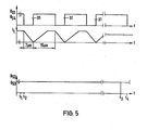
- the voltages U S1 , U S2 , U S3 and US 4 are the control voltages for the electronic switches T 1 to T 4 .
- a high voltage level means that the switch in question is controlled in the conductive state and a low voltage level means that the switch is blocked.
- the preheating phase which lasts a few hundred milliseconds, all four transistors T 1 to T 4 are conductive, so that the electrodes 14 1 and 14 2 are heated.
- the preheating phase ends at time t 1 .
- the control unit 15 then first controls the switch T 4 into the blocking state and a few microseconds later also switches T 1 .
- the circuit branch 13 was interrupted.
- the switch T 1 is blocked, the circuit branch 12 is additionally interrupted, so that no more current can flow through any of the electrodes.
- the inductance L strives to maintain the current flow and generates a high voltage which reaches the electrode 14 2 via T 2 , while the electrode 141 is connected to ground potential via T3 .
- the high voltage is above the first breakdown voltage of the switches T 1 and T 4 , so that the transistor with the lower breakdown voltage becomes conductive, although it is controlled in the blocking state.
- the breakdown voltage of T 1 or T4 thus corresponds to the ignition voltage for the fluorescent lamp.
- the inductance L can therefore discharge when the lamp is not ignited via T 1 and T 3 .
- FIG. 5 shows, numerous ignition pulses are generated in the ignition phase in order to periodically make T 1 and T 4 conductive and block them.
- the duration of each ignition pulse 31, in which T1 and T 4 are blocked, is 7 microseconds and the duration of the subsequent pulse pause, in which T 1 and T 4 are conductive, is approximately twice as long, 15 microseconds in the present exemplary embodiment.
- the period of the ignition pulses 31 is thus 22 microseconds.
- the second curve in FIG. 5 shows the course of the coil current i L through the inductance L. In the preheating phase, this current is at the value determined for preheating. If the switches T 1 and T 4 are blocked by an ignition pulse 31, then the coil current flowing through the switches T 1 and T 3 drops to zero. In the subsequent leading phase of T 1 and T 4 , the coil current rises again to the value specified by U ref . This value is maintained until the next firing pulse 31 occurs.
- the control unit 15 During each ignition process, the control unit 15 generates a certain number of control pulses 31 for, for example, 100 ignition pulses.
- the pulse pauses, in which T 1 and T 4 are conductive, are on the one hand so long that T 1 or T 4 can recover from the voltage breakdown in the conductive state, and on the other hand so short that there is no substantial recombination of the charge carriers in the fluorescent lamp 14 can.
- Due to the brief successive ignition pulses the gas in the fluorescent lamp is increasingly ionized until the ignition takes place. In this case, as is customary, a single ignition pulse is not generated, which must apply all of the ignition energy, but the ignition energy is distributed over a plurality of ignition pulses. This has the advantage that the value of the inductance L to a fraction of the otherwise usual value can be reduced.
- the control unit 15 delivers the full number of control pulses for e.g. 100 ignition pulses, regardless of when the ignition actually takes place. As a rule, only about 5 to 10 ignition pulses are required. The remaining ignition pulses are then generated when the fluorescent lamp is already lit, which is not detrimental to the operation.
- FIG. 5 shows the voltage and current profiles after the ignition. It is assumed that the switches T 1 and T 4 first become conductive immediately after the ignition, while the switches T 2 and T 3 block. In order to avoid cataphoresis on the lamp 14, the control unit 15 switches over the aforementioned switch pairs at predetermined time intervals. At the time t 3 , those switches T 2 and T 3 which were previously blocked are first switched to the conductive state. For a short period of time until time t 4 , all four switches are in the conductive state. Then the switches T 1 and T 4 , which were conductive in the previous phase, are controlled in the blocking state.
- the random generator 32 is provided in connection with the control unit 15 according to FIG.
- the random generator 32 randomly generates "ZERO" signals and "ONE" signals. It is controlled by the control pulses 31.
- the state of the output signal of the random generator 32 at the time of ignition of the fluorescent lamp determines which of the two switch pairs is initially switched on and which is off is switched. In this way it is avoided that the fluorescent lamp is always operated with the same polarity after being switched on.
- the random generator 32 replaces the integrator 18 according to FIG. 1.
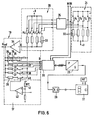
- the signal generator 24 contains four switches S 1 , S 2 , S 3 , S 4 , which are each connected to one another at one end and connected to ground and the other ends of which are connected to the supply voltages via resistors 32 with different values. Each switch is connected to an input line of the encoder 25.
- the signals M and VH described above are at two further inputs of the encoder 25.
- the encoder 25 encodes the six-digit binary signal supplied to it into a four-digit binary signal which is fed to the digital / analog converter 26. Each of these signals controls an electronic switch A 1 , A 2 , A 3 ' A 4 . One end of these switches is connected to the supply voltage + U and the other ends are each connected to a weighted resistor 33. The ends of all resistors 33 are connected to one another and to the input of an inversion amplifier 34. This input also forms the A input of the multiplier 45.
- the amplifier 34 has several parallel feedback loops.
- the one feedback loop contains a series connection of several resistors 35, each of which can be bridged by a switch 36.
- the switches 36 are controlled by the various outputs of the encoder 30. When all switches 36 are closed, all resistors 35 are in first feedback branch ineffective.
- the amplifier 34 then has a gain factor of ONE. By opening one or more switches 36, the gain factor can be increased to over 100%.
- the first feedback branch consisting of the resistors 35 is connected in parallel to a plurality of further feedback branches, each of which consists of a weighted resistor 37 and a switch 38 connected in series therewith.
- the switches 38 are also controlled by output signals from the encoder 30. By closing one or more switches 38 (with switches 36 closed) the amplification factor of the amplifier 34 is reduced to below 100%.
- a third feedback branch of the amplifier 34 contains the series connection of a resistor 39 and a switch 40.
- the switch 40 is controlled by the temperature sensor TF, which reacts with an NTC resistor 41 to the temperature of the ballast.
- the amplifier 42 provides a signal to close the switch 40. This reduces the amplification factor of the amplifier 34, so that the reference voltage U ref at the output of this amplifier also decreases.
- the comparator 16 (Fig.4) is set to a lower lamp current.
- the signals for controlling each switch 36 and 38 are supplied from encoder 30 to the B input of multiplier 45.
- encoder 30 is disabled when either M or VH is "ONE".
- the switches 36 are closed and the switches 38 are open, ie the amplifier 34 has a gain factor of ONE, so that the reference chip Uref is set to the minimum current or the preheating current depending on which of the signals M or VH is "ONE". In this case, the lamp current cannot be influenced by the signals of the dimmer 27.
- Fig. 7 shows a modified embodiment with signal generator 24a.
- the signal transmitter is not set manually here, but rather generates the signal dependent on the lamp type or the lamp power automatically.
- the two electrodes 14 . and 14 2 of the fluorescent lamp 14 connected to the input of an analog / digital converter which generates a digital output signal which (with a defined lamp current) corresponds to the lamp resistance.
- This output signal is fed to the encoder 25, which forms a signal for generating the reference signal. Thanks to its lamp resistance, the fluorescent lamp ensures that the current corresponding to the lamp power is automatically set.
- the voltage drop at each of the two electrodes 14 1 or 14 2 is fed to an analog / digital converter 43 or 44.
- the voltage drop across the electrode corresponds to the electrode resistance.
- the output signals of the analog / digital converters 43 and 44 are converted in the signal generator 24b in the encoder 25 into a control signal which is further processed by the digital / analog converter 26 in the manner described above.
Landscapes
- Circuit Arrangements For Discharge Lamps (AREA)
Abstract
Description
Die Erfindung betrifft ein Leuchtstofflampen-Vorschaltgerät mit einer Stromversorgungsschaltung, die zwei parallele Schaltungszweige speist, von denen jeder über eine Elektrode der Leuchtstofflampe führt und zwei in Reihe liegende elektronische Schalter enthält, einem Steuerwerk zum Steuern der elektronischen Schalter, einer Induktivität zur Erzeugung der Zündspannung für die Leuchtstofflampe und einem Stromfühler.The invention relates to a fluorescent lamp ballast with a power supply circuit that feeds two parallel circuit branches, each of which leads via an electrode of the fluorescent lamp and contains two electronic switches in series, a control unit for controlling the electronic switch, an inductor for generating the ignition voltage for the fluorescent lamp and a current sensor.
Die üblichen elektronischen Leuchtstofflampen-Vorschaltgeräte enthalten einen Reihenschwingkreis, der von einem Wechselrichter angestoßen wird und eine Schwingung erzeugt, deren Frequenz oberhalb des Hörbereichs des menschlichen Ohres liegt. Dem Kondensator des Reihenschwingkreises ist die Leuchtstofflampe parallel geschaltet. Derartige Vorschaltgeräte haben den Nachteil, daß die Leuchtstofflampe mit einer relativ hohen Frequenz betrieben wird und hochfrequente elektromagnetische Störungen verursacht. Bei der hohen Frequenz werden parasitäre Leitungskapazitäten wirksam, so daß zur Erzielung reproduzierbarer Eigenschaften eine definierte Leitungsführung vom Gerät zu den Leuchtstofflampen erforderlich ist. Schwierigkeiten ergeben sich insbesondere dann, wenn die Leuchtstofflampe aus der Fassung herausgenommen ist oder wenn ihr Widerstand infolge Alterung zu groß geworden ist. In solchen Fällen wird der Reihenschwingkreis unzureichend oder überhaupt nicht gedämpft, was zu Zerstörungen von Bauelementen führen kann. Aus diesem Grunde erfordern die genannten Vorschaltgeräte zusätzliche Sicherungsschaltungen, um zu gewährleisten, daß der Betrieb nur bei ordnungsgemäßer Funktion einer eingesetzten Leuchtstofflampe erfolgt. Schließlich sind die bekannten Vorschaltgeräte jeweils nur für einen engen Leistungsbereich der Leuchtstofflampe ausgelegt und für einen sehr begrenzten Bereich der Versorgungsspannungen. Für unterschiedliche Lampenleistungen, Lampenspannungen und Versorgungsspannungen müssen jeweils unterschiedliche Vorschaltgeräte eingesetzt werden.The usual electronic fluorescent lamp ballasts contain a series resonant circuit that is triggered by an inverter and generates an oscillation whose frequency is above the hearing range of the human ear. The fluorescent lamp is connected in parallel to the capacitor of the series resonant circuit. Such ballasts have the Disadvantage that the fluorescent lamp is operated at a relatively high frequency and causes high-frequency electromagnetic interference. At the high frequency, parasitic line capacitances become effective, so that in order to achieve reproducible properties, a defined line routing from the device to the fluorescent lamps is required. Difficulties arise particularly when the fluorescent lamp is removed from the socket or when its resistance has become too great due to aging. In such cases, the series resonant circuit is damped insufficiently or not at all, which can lead to the destruction of components. For this reason, the ballasts mentioned require additional safety circuits to ensure that operation only takes place when a fluorescent lamp used is functioning properly. Finally, the known ballasts are each designed only for a narrow power range of the fluorescent lamp and for a very limited range of supply voltages. Different ballasts must be used for different lamp powers, lamp voltages and supply voltages.
Bei einem bekannten Vorschaltgerät der eingangs genannten Art (DE-OS 29 42 468) sind vier elektronische Schalter, die von einem logischen Steuerwerk gesteuert sind, nach Art einer Brückenschaltung geschaltet, in deren Querzweig die Leuchtstofflampe liegt. In der Vorheizphase sind bestimmte Schalter leitend, so daß Gleichstrom durch die Elektroden der Leuchtstofflampe fließt. Zum Zünden der Gasentladung werden zwei diagonal einander gegenüberliegende Schalter gesperrt, so daß nunmehr ein Strom, der durch die Entladung einer Induktivität unterstützt wird, durch die Leuchtstofflampe fließt. Die Schalter werden anschließend mit einer hochfrequenten Wechselspannung von über 10 kHz getaktet, wodurch die Leuchtstofflampe mit der genannten Frequenz periodisch umgepolt wird. In einem der Schaltungszweige ist ein Stromfühler vorgesehen, der jedoch nur dazu dient, das Zünden der Leuchtstofflampe festzustellen und nach einer bestimmten Zahl vergeblicher Zündversuche das Steuerwerk abzuschalten.In a known ballast of the type mentioned (DE-OS 29 42 468) four electronic switches, which are controlled by a logic control unit, are connected in the manner of a bridge circuit, in the transverse branch of which the fluorescent lamp is located. In the preheating phase, certain switches are conductive so that direct current flows through the electrodes of the fluorescent lamp. To ignite the gas discharge, two diagonally opposite switches are blocked, so that a current which is supported by the discharge of an inductor now flows through the fluorescent lamp. The switches are then with egg ner high-frequency AC voltage of over 10 kHz clocked, whereby the fluorescent lamp is periodically reversed with the frequency mentioned. A current sensor is provided in one of the circuit branches, but is only used to determine the ignition of the fluorescent lamp and to switch off the control unit after a certain number of unsuccessful ignition attempts.
Bei den bekannten Vorschaltgeräten erfolgt die Versorgung der Leuchtstofflampe mit einer hochfrequenten Spannung, wobei der Lampenstrom von verschiedenen Parametern abhängt, beispielsweise vom Lampenwiderstand. Dies hat zur Folge, daß Lampen unterschiedlicher Leistung jeweils ein anderes Vorschaltgerät erfordern und daß die Lampenleistung sich im Laufe der Lebensdauer der Lampe infolge des ansteigenden Widerstandes verändern kann.In the known ballasts, the fluorescent lamp is supplied with a high-frequency voltage, the lamp current depending on various parameters, for example the lamp resistance. The consequence of this is that lamps of different wattages each require a different ballast and that the lamp wattage can change over the course of the life of the lamp due to the increasing resistance.
Der Erfindung liegt die Aufgabe zugrunde, ein Leuchtstofflampen-Vorschaltgerät der eingangs genannten Art zu schaffen, das für Lampen mit unterschiedlichen Lampenleistungen und unterschiedlichen Lampenspannungen gleichermaßen einsetzbar ist.The invention has for its object to provide a fluorescent lamp ballast of the type mentioned, which can be used equally for lamps with different lamp powers and different lamp voltages.
Die Lösung dieser Aufgabe besteht erfindungsgemäß darin, daß der Stromfühler und die Induktivität mit den beiden Schaltungszweigen in Reihe geschaltet sind und daß der Stromfühler ein ebenfalls in der Reihenschaltung liegendes Schaltglied in der Weise steuert, daß dieses Schaltglied den Stromkreis öffnet, wenn der Strom einen bestimmten ersten Schwellenwert übersteigt, und den Stromkreis schließt, wenn der Strom einen bestimmten zweiten Schwellenwert, der niedriger ist als der erste Schwellenwert, unterschreitet.The solution to this problem is, according to the invention, that the current sensor and the inductor are connected in series with the two circuit branches and that the current sensor controls a switching element which is also connected in series in such a way that this switching element opens the circuit when the current has a specific value exceeds the first threshold and closes the circuit when the current falls below a certain second threshold that is lower than the first threshold.
Durch das Zusammenwirken des Stromfühlers mit dem Schaltglied und der Induktivität wird erreicht, daß der von den Schaltungszweigen aufgenommene Strom, also der Lampenstrom, ständig im Bereich zwischen dem ersten und dem zweiten Schwellenwert bleibt und somit praktisch konstant gehalten wird. Der Lampe wird also ein definierter Strom zugeführt, der unabhängig ist von der Höhe der extern angelegten Spannung und auch unabhängig vom Lampenwiderstand. Die Konstanthaltung des Lampenstroms erfolgt nahezu verlustlos, weil das Schaltglied sich in jeder Phase entweder im Einschaltzustand oder im Ausschaltzustand befindet. Wenn das Schaltglied im Einschaltzustand ist, erhöht sich der Strom durch die im Lampenstromkreis liegende Induktivität langsam, bis der erste Schwellenwert erreicht ist. Daraufhin wird das Schaltglied gesperrt, so daß sich die Induktivität entlädt und der Strom langsam bis auf den zweiten Schwellenwert absinkt. Die Induktivität, die für einen langsamen Anstieg und langsamen Abfall des Lampenstromes innerhalb der von den beiden Schwellenwerten vorgegebenen Bandbreite sorgt, kann gleichzeitig dazu genutzt werden, die zum Zünden der Leuchtstofflampe erforderliche hohe Spannung zu erzeugen.Due to the interaction of the current sensor with the switching element and the inductor is achieved that the current drawn by the circuit branches current, ie the L ampenstrom constantly remains in the range between the first and the second threshold value and is thus kept almost constant. A defined current is therefore supplied to the lamp, which is independent of the level of the externally applied voltage and also independent of the lamp resistance. The lamp current is kept almost lossless because the switching element is either in the on state or in the off state in each phase. When the switching element is in the on state, the current through the inductance in the lamp circuit increases slowly until the first threshold value is reached. The switching element is then blocked so that the inductance discharges and the current slowly drops to the second threshold value. The inductance, which ensures a slow increase and slow decrease in the lamp current within the bandwidth specified by the two threshold values, can simultaneously be used to generate the high voltage required to ignite the fluorescent lamp.
Gemäß einer bevorzugten Weiterbildung der Erfindung ist vorgesehen, daß die Schwellenwerte in Abhängigkeit von mindestens einem Steuersignal einzeln oder gemeinsam veränderbar sind. Auf diese Weise kann das Vorschaltgerät beispielsweise eine Dimmerfunktion ausüben, wenn die Schwellenwerte durch ein manuell beeinflußbares Steuersignal verändert werden. Wenn die Schwellenwerte hoch sind, ist der Lampenstrom groß und die Lampe leuchtet hell; werden die Schwellenwerte erniedrigt, so wird der Lampenstrom kleiner und die Lampe leuchtet weniger hell. Es besteht auch die Möglichkeit, die Schwellenwerte selbsttätig zu regeln, beispielsweise in Abhängigkeit von der Beleuchtungsstärke, die in dem Raum herrscht, in dem sich die Leuchtstofflampe befindet oder in Abhängigkeit von der Lampentemperatur.According to a preferred development of the invention, it is provided that the threshold values can be changed individually or together depending on at least one control signal. In this way, the ballast can, for example, perform a dimmer function if the threshold values are changed by a control signal which can be influenced manually. If the thresholds are high, the lamp current is high and the lamp is bright; If the threshold values are lowered, the lamp current becomes smaller and the lamp shines less brightly. There is also the possibility that To regulate threshold values automatically, for example depending on the illuminance prevailing in the room in which the fluorescent lamp is located or depending on the lamp temperature.
Ein besonderer Vorteil besteht darin, daß das Vorschaltgerät mit unterschiedlichen Versorgungsspannungen gespeist werden kann, beispielsweise mit einer Netzspannung von 110 V und einer Frequenz von 60 Hz oder mit einer Netzspannung von 220 V und 50 Hz. Da der Lampenstrom unabhängig von der Versorgungsspannung konstant gehalten wird, arbeitet das Vorschaltgerät bei unterschiedlichen Versorgungsspannungen ohne Umschaltung. Vorzugsweise sind die beiden Schwellenspannungen gemeinsam veränderbar, so daß sich bei einer Veränderung der Stromamplitude die Bandbreite der Stromschwankungen nicht verändert.A particular advantage is that the ballast can be supplied with different supply voltages, for example with a mains voltage of 110 V and a frequency of 60 Hz or with a mains voltage of 220 V and 50 Hz. Since the lamp current is kept constant regardless of the supply voltage , the ballast works with different supply voltages without switching. The two threshold voltages can preferably be changed together, so that the bandwidth of the current fluctuations does not change when the current amplitude changes.
Gemäß einer bevorzugten Weiterbildung der Erfindung erfolgt die Steuerung der elektronischen Schalter derart, daß die Leuchtstofflampe mit einer unterhalb von 100 Hz liegenden Frequenz umgepolt wird. Die Umpolfrequenz sollte unter 1 Hz und vorzugsweise unter 1 mHz liegen. Die Leuchtstofflampe wird hierbei gewissermaßen mit Gleichstrom betrieben, wobei in relativ großen Zeitabständen eine Umpolung erfolgt. Die Umpolung ist zur Verhinderung von Kataphorese in der Leuchtstofflampe erforderlich. Kataphorese entsteht, wenn die Lampe längere Zeit mit gleicher Polarität betrieben wird. Es handelt sich um eine Quecksilberverlagerung zur Ka-thode hin, die durch Umpolen der Lampe rückgebaut werden kann. Das Umpolen kann in relativ großen Zeitabständen von z.B. einer Stunde erfolgen. Dies würde einer Umpolfrequenz von ca. 0,3 mHz entsprechen. Während die üblichen Vorschaltgeräte mit einer oberhalb des Hörbereichs liegenden hohen Frequenz arbeiten, wird erfindungsgemäß die Umpolungsfrequenz der Lampe niedrig gemacht. Der Lampenstrom wird in jeder Halbperiode konstant gehalten, die Umschaltung erfolgt nur von Zeit zu Zeit, um Kataphorese zu vermeiden.According to a preferred development of the invention, the electronic switches are controlled in such a way that the fluorescent lamp is reversed with a frequency below 100 Hz. The polarity reversal frequency should be below 1 Hz and preferably below 1 mHz. The fluorescent lamp is operated to a certain extent with direct current, with a polarity reversal taking place at relatively large time intervals. The polarity reversal is necessary to prevent cataphoresis in the fluorescent lamp. Cataphoresis occurs when the lamp is operated with the same polarity for a long time. It is a mercury displacement for a K-Thode out, which can be dismantled by reversing the polarity of the lamp. The polarity reversal can take place at relatively large intervals of, for example, one hour. This would correspond to a pole reversal frequency of approx. 0.3 mHz. While the usual ballasts with one above the According to the invention, the polarity reversal frequency of the lamp is made low. The lamp current is kept constant in every half period, the switchover is only from time to time to avoid cataphoresis.
Vorzugsweise ist eine Integrationseinrichtung vorgesehen, die während jeder Periode des durch die Leuchtstofflampe fließenden Stromes das Zeitintegral über diesen Strom bildet und die nächste Periode einleitet, wenn dieses Integral 0 geworden ist. Die Umpolung der Leuchtstofflampe erfolgt hierbei nicht unbedingt mit konstanter Halbperiodendauer. Bei den relativ langen Halbperioden kann es vorkommen, daß der Lampenstrom in der zweiten Halbperiode sich von demjenigen der ersten Halbperiode unterscheidet, z.B. wenn der Lampenstrom durch Dimmen verändert worden ist. Damit die Lampe in beiden Halbperioden gleichermaßen beansprucht wird, wird in jeder der Halbperioden das Zeitintegral über den Strom gebildet, und wenn die Integrale der positiven und der negativen Halbperiode einander gleich sind, wird die Periode beendet. Die Integralbildung erfolgt insbesondere bei langen Halbperioden vorzugsweise dadurch, daß die Stromwerte in digitale Form umgesetzt und kumulativ aufaddiert werden.An integration device is preferably provided which forms the time integral over this current during each period of the current flowing through the fluorescent lamp and initiates the next period when this integral has become zero. The polarity reversal of the fluorescent lamp does not necessarily take place with a constant half-period. In the relatively long half-periods, the lamp current in the second half-period may differ from that in the first half-period, e.g. if the lamp current has been changed by dimming. In order for the lamp to be equally loaded in both half-periods, the time integral is formed over the current in each of the half-periods, and when the integrals of the positive and negative half-periods are equal to one another, the period is ended. The integral formation takes place, particularly in the case of long half-periods, preferably by converting the current values into digital form and adding them up cumulatively.
Da bei dem erfindungsgemäßen Vorschaltgerät der Strom geregelt wird, ergeben sich zahlreiche Möglichkeiten der Beeinflussung dieses Stromes zur Erzielung unterschiedlicher Betriebszustände der Leuchtstofflampe. Ein besonderer Vorteil besteht darin, daß das Vorschaltgerät ohne bauliche Veränderungen für Leuchtstofflampen mit unterschiedlichen Leistungen benutzt werden kann, indem die Größe des Lampenstromes entsprechend der jeweiligen Lampenleistung eingestellt wird. Diese Einstellung kann entweder an einem manuell verstellbaren Signalgeber erfolgen oder auch in Abhängigkeit von Parametern der in das Vorschaltgerät eingesetzten Leuchtstofflampe. Im zuletzt genannten Fall erfolgt die Einstellung des Lampenstroms, den die betreffende Leuchtstofflampe benötigt, selbsttätig.Since the current is regulated in the ballast according to the invention, there are numerous possibilities for influencing this current in order to achieve different operating states of the fluorescent lamp. A particular advantage is that the ballast can be used without structural changes for fluorescent lamps with different powers by the size of the lamp current according to the lamp power is set. This setting can be made either on a manually adjustable signal transmitter or depending on the parameters of the fluorescent lamp used in the ballast. In the latter case, the lamp current required by the fluorescent lamp in question is set automatically.
Das erfindungsgemäße Vorschaltgerät ermöglicht auch den Einsatz einer Dimmerschaltung, mit der der Lampenstrom in Abhängigkeit von einem externen Steuersignal verändert wird. Dieses Steuersignal kann entweder durch manuelles Verstellen der Dimmerschaltung oder durch einen externen Meßfühler erzeugt werden.The ballast according to the invention also enables the use of a dimmer circuit with which the lamp current is changed as a function of an external control signal. This control signal can be generated either by manually adjusting the dimmer circuit or by an external sensor.
Ein besonderes Problem bei Leuchtstofflampen-Vorschaltgeräten bildet das Starten der Leuchtstofflampe. Vor dem Starten werden die Elektroden der Leuchtstofflampe mit Gleichströmen eine bestimmte Zeit lang vorgeheizt. Danach werden bei den bekannten Vorschaltgeräten hintereinander mehrere Zündversuche unternommen, indem beide Schaltungszweige, die über die Elektroden der Leuchtstofflampe führen, unterbrochen werden, d.h. indem je einer der elektronischen Schalter kurzzeitig für den Stromdurchgang gesperrt wird. Die Induktivität liefert dann kurzzeitig eine hohe Zündspannung. Gemäß einer bevorzugten Ausführungsform der Erfindung werden zahlreiche kurze Zündimpulse mit kurzen zeitlichen Ab-ständen geliefert, um je ein Paar der diagonal angeordneten elektronischen Schalter periodisch zu öffnen und zu schließen. Die Folgefrequenz der Zündimpulse ist so hoch, daß sich die Ladungsträger im Innern der Leuchtstofflampe zwischen zwei Zündimpulsen nicht wesentlich rekombinieren können. Auf diese Weise erfolgt nach mehreren Zündimpulsen die Zündung. Die Zündfähigkeit der Leuchtstofflampe baut sich nach Art einer Treppenkurve auf. Ein besonderer Vorteil besteht darin, daß die zum Zünden erforderliche Induktivität relativ klein gehalten werden kann. Diese Induktivität verkleinert sich gegenüber der üblichen Zündung mit Einzelimpulsen etwa um den Faktor n, wobei n die Zahl der kurzzeitig aufeinanderfolgenden Zündimpulse darstellt. Durch die kleinere Induktivität werden nicht nur die erforderlichen Spulenabmessungen und das Eisengewicht, sondern auch die gespeicherte Energie verringert. Die elektronischen Schalter werden auch bei Spannungsdurchbrüchen nicht zerstört, da die in der Spule gespeicherte geringe Energie hierzu nicht ausreicht. Der zum Zünden benutzte elektronische Schalter wird nur solange im Sperrzustand gehalten, daß an diesem Schalter zwar ein reversibler Spannungsdurchbruch entsteht, der Schalter aber nicht zerstört wird. Bei dem Spannungsdurchbruch verhält sich der gesperrte elektronische Schalter wie eine Zenerdiode. Der zur Zerstörung führende zweite Durchbruch, der als thermischer Durchbruch bezeichnet wird, wird durch die Strombegrenzung vermieden.A particular problem with fluorescent lamp ballasts is starting the fluorescent lamp. Before starting, the electrodes of the fluorescent lamp are preheated for a certain time with direct currents. Thereafter, several ignition attempts are made in succession in the known ballasts by interrupting both circuit branches which lead over the electrodes of the fluorescent lamp, ie by briefly blocking one of the electronic switches for the passage of current. The inductance then briefly supplies a high ignition voltage. According to a preferred embodiment of the invention, numerous short firing pulses are with short time A b stands supplied to one pair of diagonally arranged electronic switch to open and close periodically. The repetition frequency of the ignition pulses is so high that the charge carriers in the interior of the fluorescent lamp cannot essentially recombine between two ignition pulses. In this way, the ignition takes place after several ignition pulses. The ignitability of the Fluorescent lamp builds up like a staircase curve. A particular advantage is that the inductance required for ignition can be kept relatively small. This inductance is reduced by a factor of n compared to the usual ignition with individual pulses, where n represents the number of briefly successive ignition pulses. The smaller inductance not only reduces the required coil dimensions and iron weight, but also the stored energy. The electronic switches are not destroyed even in the event of voltage breakdowns, since the low energy stored in the coil is not sufficient for this. The electronic switch used for ignition is only held in the blocking state for as long as a reversible voltage breakdown occurs at this switch, but the switch is not destroyed. In the event of a voltage breakdown, the blocked electronic switch behaves like a zener diode. The second breakdown leading to destruction, which is referred to as thermal breakdown, is avoided by the current limitation.
Im folgenden werden unter Bezugnahme auf die Zeichnungen Ausführungsbeispiele der Erfindung näher erläutert.Exemplary embodiments of the invention are explained in more detail below with reference to the drawings.
Es zeigen:
- Fig. 1 ein schematisches Schaltbild eines ersten Ausführungsbeispiels des Vorschaltgeräts,
- Fig. 2 ein Diagramm zur Verdeutlichung der Erzeugung des Lampenstroms,
- Fig. 3 ein Diagramm zur Erläuterung der Umpolung des Lampenstroms,
- Fig. 4 ein Blockschaltbild eines zweiten Ausführungsbeispiels des Vorschaltgerätes,
- Fig. 5 verschiedene Spannungs- und Stromverläufe bei dem Vorschaltgerät nach Fig. 4 während des Zündens und danach,
- Fig. 6 eine Darstellung der Schaltung zur Erzeugung des Referenzsignals bei dem Vorschaltgerät nach Fig.4,
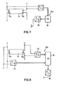
- Fig. 7 eine Modifikation des Signalgebers aus Fig.6, und
- Fig. 8 eine weitere Modifikation des Signalgebers.
- 1 is a schematic circuit diagram of a first embodiment of the ballast,
- 2 shows a diagram to illustrate the generation of the lamp current,
- 3 is a diagram for explaining the polarity reversal of the lamp current,
- 4 shows a block diagram of a second exemplary embodiment of the ballast,
- 5 different voltages and currents in the ballast of FIG. 4 during ignition and afterwards,
- 6 shows the circuit for generating the reference signal in the ballast according to FIG. 4,
- Fig. 7 shows a modification of the signal generator from Fig. 6, and
- Fig. 8 shows a further modification of the signal generator.
Das in Fig. 1 dargestellte Vorschaltgerät weist eine Gleichrichterschaltung 10 auf, die über einen Tiefpaß 11 zur Eliminierung von Störspannungen aus dem oder in das Versorgungsnetz mit einer Wechselspannung gespeist wird. Die Gleichrichterschaltung 10 erzeugt am Kondensator C eine Gleichspannung, die nicht geregelt sein muß, und deren Höhe von der angelegten Netzspannung abhängig sein kann.The ballast shown in FIG. 1 has a
An den Pluspol der Versorgungsspannung ist das Schaltglied TS angeschlossen, bei dem es sich um einen Schalttransistor handelt. Aus Gründen des einfacheren Verständnisses sind das Schaltglied T und die nachfolgend noch zu beschreibenden elektronischen Schalter in der Zeichnung als mechanische Schalter dargestellt. Das Schaltglied TS ist mit dem Stromfühler I und der Induktivität L in Reihe geschaltet. An diese Reihenschaltung ist die Parallelschaltung der beiden Schaltungszweige 12 und 13 angeschlossen. Das andere Ende dieser Parallelschaltung ist mit dem Minuspol des Gleichrichters 10 verbunden.The switching element T S , which is a switching transistor, is connected to the positive pole of the supply voltage. For reasons of easier understanding, the switching element T and the electronic switches to be described below are shown in the drawing as mechanical switches. The switching element T S is connected in series with the current sensor I and the inductance L. The parallel connection of the two
Der Schaltungszweig 12 enthält die elektronischen Schalter T1 und T3, zwischen die die eine Elektrode 141 der Leuchtstofflampe 14 geschaltet ist. Der andere Schaltungszweig 13 enthält die Reihenschaltung der Transistoren T2 und T4, zwischen die die zweite Elektrode 142 der Leuchtstofflampe 14 geschaltet ist.The
Die Schalter T1 bis T4 werden von dem logischen Steuerwerk 15 gesteuert, bei dem es sich beispielsweise um einen Mikroprozessor handeln kann.The switches T 1 to T 4 are controlled by the
Es sei angenommen, daß die Schalter T1 bis T4 im leitenden Zustand sind oder daß auf andere Weise über die von den Schaltungszweigen 12,13 und der Lampe 14 gebildete Brückenschaltung ein Strom fließen kann. Wenn dann das Schaltglied TS leitend wird, fließt ein Strom durch den Stromfühler I, die Induktivität L und die Brückenschaltung. Dieser Strom iL, der in Fig. 2 dargestellt ist, baut sich infolge der Induktivität L langsam auf, wobei der Anstieg als linear angenommen werden kann. Der Ausgang des Stromfühlers I ist mit dem B-Eingang eines Komparators 16 mit Hysterese verbunden, dessen Ausgang das Schaltglied TS steuert. Der A-Eingang des Komparators empfängt von dem Steuerwerk 15 eine Referenzspannung Uref. Der Komparator 16 erzeugt aus der Referenzspannung zwei Schwellenwerte, von denen der eine einem maximalen Lampenstrom iLmax und der andere einem minimalen Lampenstrom iLmin entspricht. Wenn der Lampenstrom den maximalen Schwellenwert iZ max erreicht, sperrt der Komparator 16 das Schaltglied TS, d.h. der Reihenstromkreis wird unterbrochen. Die Induktivität L versucht nun, den Strom, der zuvor geflossen ist, aufrechtzuerhalten, so daß der Spulenstrom iL langsam abfällt. Wenn dieser Strom den unteren Grenzwert iZ min erreicht, schaltet der Komparator 16 das Schaltglied TS wieder in den leitenden Zustand, wodurch der Lampenstrom iL im Reihenstromkreis wieder ansteigt. In Fig. 2 ist der zeitliche Verlauf des Spannungsabfalls UL an der Induktivität L und der zeitliche Verlauf des Stromes iL dargestellt. Man erkennt, daß der Strom sich innerhalb der Grenzwerte iLmax und iLmin, die relativ nahe beieinander liegen, zeitlich verändert, und nahezu konstant bleibt. Die Höhe des Bandes zwischen iLmax und iLmin kann durch die vom Steuerwerk 15 dem Komparator 16 zugeführte Steuerspannung verändert werden. Der zeitliche Verlauf des Stromes i, der dem Gleichrichter 10 entnommen wird, ist in Fig. 1 dargestellt. Dieser Strom ist sägezahnförmig, wobei die einzelnen Sägezähne durch Lücken voneinander getrennt sind. Damit bei gesperrtem Schaltglied TS der Lampenstrom fließen kann, ist die Ausgangsseite dieses Schaltgliedes über eine Freilaufdiode 17 mit dem negativen Pol der Gleichrichterschaltung 10 verbunden. An diesen negativen Pol ist die Anode der Freilaufdiode 17 angeschlossen.It is assumed that the switches T 1 to T 4 are in the conductive state or that a current can flow in another way via the bridge circuit formed by the
Vor dem Starten der Lampe 14 werden die Elektroden 141 und 142 zunächst aufgeheizt. Hierzu werden alle vier Schalter T1 bis T4 in den leitenden Zustand gesteuert. Nach einer definierten Vorheizzeit werden zwei einander diagonal gegenüberliegende Schalter, beispielsweise die Schalter T1 und T4 gesperrt. Gleichzeitig kann durch entsprechende Steuerung des Komparators 16 der Strom iL verändert werden. Die Induktivität L erzeugt infolge der Stromänderung den für das Zünden der Lampe 14 erforderlichen Spannungsanstieg. Die Lampe wird nun über längere Zeit, z.B. über eine Stunde, über die Schalter T2 und T3 betrieben, wobei die Elektrode 142 positives Potential und die Elektrode 141 negatives Potential hat.Before starting the
In Fig. 3 ist der Lampenstrom iL über der Zeit t dargestellt, wobei jedoch der Zeitmaßstab viel größer ist als derjenige von Fig. 2. Während der ersten Halbperiode 1 HP, in der diese Polung aufrechterhalten wird, wird das Ausgangssignal des Stromfühlers I von dem Integrator 18 integriert. Aus Fig. 3 ist ersichtlich, daß das Integral f iL dt mit der Zeit linear ansteigt. Dieses Integral wird vom Integrator 18 dem Steuerwerk 15 zugeführt. Wenn das Integral einen vorgegebenen Maximalwert erreicht hat, bewirkt das Steuerwerk 15, daß die Schalter T1 und T4 leitend gehalten werden und nachfolgend die Schalter T2 und T3 gesperrt werden. Der Strom fließt dann über T1, die Lampe 14 und T4, so daß die Lampe 14 umgepolt wird. Gleichzeitig mit der Umpolung wird der Integrator 18 umgesteuert, so daß er nunmehr abwärts integriert. Die Aufwärts- und Abwärtsintegration wird über die Leitungen 19 vom logischen Steuerwerk 15 gesteuert. Wenn das Integral den Wert 0 erreicht hat, wird die zweite Halbperiode 2HP beendet und die Schalter T2 und T3 werden wieder leitend, und nachfolgend die Schalter T1 und T4 gesperrt. Durch den Integrator 18 wird also erreicht, daß das Stromintegral in der ersten Halbperiode gleich dem Stromintegral in der zweiten Halbperiode ist. Auf diese Weise werden unterschiedliche Stromstärken, die zwischenzeitlich durch den Komparator 16 verursacht sein können, berücksichtigt, und es wird erreicht, daß die Strombeaufschlagung der Lampe 14 in beiden Richtungen gleich ist.3 shows the lamp current i L over time t, but the time scale is much larger than that of FIG. 2. During the first half period 1 HP, in which this polarity is maintained, the output signal of the current sensor I is integrated by the
Das Ausführungsbeispiel der Fig. 4 bis 6 entspricht weitgehend dem ersten Ausführungsbeispiel, so daß nachfolgend lediglich die Unterschiede erläutert werden. Komponenten, die in beiden Ausführungsbeispielen die gleiche Funktion haben, sind mit denselben Bezugszeichen versehen, so daß nachfolgend lediglich die Unterschiede bzw. zusätzlichen Merkmale erläutert werden. Gemäß Fig. 4 ist das elektronische Schaltglied T an die Induktivität L angeschlossen und das andere Ende der Induktivität L ist mit dem einen Ende der beiden parallelen Schaltungszweige 12, 13 verbunden. Das andere Ende dieser Schaltungszweige 12, 13 ist über den als niederohmigen Widerstand 20 ausgebildeten Stromfühler I mit Massepotential verbunden.The embodiment of FIGS. 4 to 6 largely corresponds to the first embodiment, so that only the differences are explained below. Components that have the same function in both exemplary embodiments are provided with the same reference symbols, so that only the differences or additional features are explained below. 4, the electronic switching element T is connected to the inductor L and the other end of the inductor L is connected to one end of the two
Die elektronischen Schalter T1 und T4 werden von dem Steuerwerk 15 über die Ansteuerschaltung 21 gesteuert und die elektronischen Schalter T2 und T3 werden von dem Steuerwerk 15 über die Ansteuerschaltung 22 gesteuert. Eine weitere Transistor-Ansteuerschaltung 23 ist zwischen den Ausgang des Komparators 16 und das Schaltglied T geschaltet.The electronic switches T 1 and T 4 are controlled by the
Am negativen Eingang des Komparators 16 steht die am Stromfühler I erzeugte Spannung an und dem positiven Eingang wird das Referenzsignal Uref zugeführt. Dieses Referenzsignal bestimmt den Wert, den der Lampenstrom annimmt.The voltage generated at the current sensor I is present at the negative input of the
Das Vorschaltgerät enthält einen Signalgeber 24, der bei dem vorliegenden Ausführungsbeispiel aus vier manuell einstellbaren Schaltern besteht. An diesen Schaltern kann eine Schalterkombination entsprechend der jeweiligen Leistungsstufe eingestellt werden, zu der die Leuchtstofflampe 14 gehört. Von jedem der Schalter des Signalgebers 24 führt eine Leitung zu dem Kodierer 25. Einem weiteren Eingang des Kodierers 25 wird ein Signal VH zugeführt, das von dem Steuerwerk 15 geliefert wird und das angibt, ob das Vorschaltgerät sich in der Vorheizphase befindet oder nicht. Der Kodierer 25 weist noch einen sechsten Eingang auf, dem ein Signal M zugeführt wird, welches angibt, ob im Lampenkreis ein Mindeststrom fließt oder nicht. Der Mindeststrom ist ein Ruhestrom, der aufrechterhalten wird, solange die Lampe 14 in die Fassung eingesetzt ist. Es handelt sich um einen Ruhestrom, durch den die Schaltung überwacht und betriebsbereit gehalten wird. Solange der Mindeststrom nicht überschritten wird, ist das Signal M "EINS" und wenn der Mindeststrom überschritten wird, ist dieses Signal "NULL".The ballast contains a
Der Kodierer 25 erzeugt aus den ihm zugeführten sechs Binärsignalen ein Digitalsignal, das ein Maß für den momentanen Lampenstrom darstellt. Dieses Digitalsignal wird einem Digital/Analog-Umsetzer 26 zugeführt, der ein entsprechendes Analog-Signal an den A-Eingang des Multiplizierers 45 legt.The
Das Mindeststromsignal M wird von einem Differenzverstärker 46 erzeugt, der an einem Eingang ein Schwellwertsignal 47 empfängt und dessen anderer Eingang mit dem Ausgang des Stromfühlers I verbunden ist.The minimum current signal M is generated by a
Der Kodierer 25 besteht beispielsweise aus einer Kodiermatrix. Er ist so ausgebildet, daß er aus dem Ausgangssignal des Signalgebers 24 und dem Signal VH einen digitalen Wert bildet, der die Größe des Lampenstromes für den jeweiligen Lampentyp angibt, und zwar sowohl für die Vorheizphase als auch für die Betriebsphase. Dies gilt jedoch nur, solange das Signal M "NULL" ist. Ist das Signal M "EINS", dann wird unabhängig von dem Signal des Signalgebers 24 und von dem Signal VH ein ganz bestimmtes Signal ausgegeben, das der Größe des zu erzeugenden Mindeststromes entspricht.The
Um die Leuchtstofflampe dimmen zu können, ist ein Dimmer 27 an das Vorschaltgerät angeschlossen. Das digitale Ausgangssignal des Dimmers 27 wird über einen Optokoppler 28 in serieller Form einem Serien/Parallel-Wandler 29 zugeführt, der ein Schieberegister enthält. Das Ausgangssignal des Serien/Parallel-Wandlers 29 wird über einen Kodierer 30 dem B-Eingang des Multiplizierers 45 zugeführt. Der Kodierer 30 wird für den Signaldurchgang gesperrt, wenn mindestens eines der Signale VH oder M auftritt. In diesem Fall werden die Signale des Dimmers 27 wirkungslos. Wenn der B-Eingang des Multiplizierers 45 kein Signal empfängt, wird das dem A-Eingang zugeführte Signal mit dem Faktor 1 multipliziert. Wenn dagegen am B-Eingang ein Signal auftritt, wird das Analog-Signal A mit einem dem digitalen Signal B entsprechenden Analogwert miltipliziert. Das Signal B gibt den prozentualen Anteil des Lampenstromes vom Nennstrom an. Dieser prozentuale Anteil kann unter 100% aber auch über 100% liegen. Leuchtstofflampen können vorübergehend auch mit einem über dem Nennstrom liegenden Lampenstrom betrieben werden, ohne Schaden zu nehmen.In order to be able to dim the fluorescent lamp, a dimmer 27 is connected to the ballast. The digita The output signal of the dimmer 27 is fed via an
Der Dimmer 27 muß nicht notwendigerweise manuell verstellbar sein. Bei dem vorliegenden Ausführungsbeispiel ist er mit einem Meßfühler MF verbunden, der beispielsweise die Beleuchtungsstärke feststellt und ein entsprechendes Steuersignal an den Dimmer 27 liefert, um diese Beleuchtungsstärke auf einen konstanten Wert einzuregeln. Anstelle des Meßfühlers MF kann auch eine Schaltuhr o.dgl. vorgesehen sein.The dimmer 27 does not necessarily have to be manually adjustable. In the present exemplary embodiment, it is connected to a sensor MF, which, for example, determines the illuminance and supplies a corresponding control signal to the dimmer 27 in order to regulate this illuminance to a constant value. Instead of the sensor MF, a timer or the like can also be used. be provided.
Das Ubertragungsverhalten des Multiplizierers 45 wird von dem Signal eines Temperaturfühlers TF beeinflußt, der an dem Vorschaltgerät angebracht ist. Auf diese Weise kann z.B. die Lampenleistung verringert werden, wenn die Temperatur des Vorschaltgerätes über einen vorgegebenen Wert hinaus ansteigt.The transmission behavior of the
In Fig. 5 sind verschiedene Impulsverläufe beim Zünden der Leuchtstofflampe dargestellt. Die Spannungen US1, US2,US3 und US4 sind die Steuerspannungen für die elektronischen Schalter T1 bis T4. Ein hohes Spannungsniveau bedeutet jeweils, daß der betreffende Schalter in den leitenden Zustand gesteuert wird und ein.niedriges Spannungsniveau bedeutet, daß der Schalter gesperrt wird.5 shows various pulse profiles when the fluorescent lamp is ignited. The voltages U S1 , U S2 , U S3 and US 4 are the control voltages for the electronic switches T 1 to T 4 . A high voltage level means that the switch in question is controlled in the conductive state and a low voltage level means that the switch is blocked.
In der Vorheizphase, die einige hundert Millisekunden dauert, sind alle vier Transistoren T1 bis T4 leitend, so daß die Elektroden 141 und 142 aufgeheizt werden. Zum Zeitpunkt t1 ist die Vorheizphase beendet. Das Steuerwerkt 15 steuert dann zunächst den Schalter T4 in den Sperrzustand und wenige µs danach auch den Schalter T1. Beim Sperren des Schalters T4 wurde der Schaltungszweig 13 unterbrochen. Beim Sperren des Schalters T1 wird zusätzlich der Schaltungszweig 12 unterbrochen, so daß über keine der Elektroden mehr Strom fließen kann. Die Induktivität L ist aber bestrebt, den bisherigen Stromfluß aufrechtzuerhalten und erzeugt dabei eine Hochspannung, die über T2 an die Elektrode 142 gelangt, während die Elektrode 141 über T3 an Massepotential liegt. Die Hochspannung liegt über der ersten Durchbruchspannung der Schalters T1 und T4, so daß der Transistor mit der niedrigeren Durchbruchspannung leitend wird, obwohl er in den Sperrzustand gesteuert ist. Die Durchbruchspannung von T1 oder T4 entspricht also der Zündspannung für die Leuchtstofflampe. Die Induktivität L kann sich daher bei nicht gezündeter Lampe über T1 und T3 entladen.In the preheating phase, which lasts a few hundred milliseconds, all four transistors T 1 to T 4 are conductive, so that the
Wie Fig. 5 zeigt, werden in der Zündphase zahlreiche Zündimpulse erzeugt, um T1 und T4 gemeinsam periodisch leitend zu machen und zu sperren. Die Dauer eines jeden Zündimpulses 31, bei dem T1 und T4 gesperrt sind, beträgt 7 µs und die Dauer der darauffolgenden Impulspause, in der T1 und T4 leitend sind, ist etwa doppelt so groß, beim vorliegenden Ausführungsbeispiel 15 µs. Die Periodendauer der Zündimpulse 31 beträgt somit 22 µs. Die zweite Kurve in Fig. 5 zeigt den Verlauf des Spulenstroms iL durch die Induktivität L. In der Vorheizphase ist dieser Strom auf dem zum Vorheizen bestimmten Wert. Werden die Schalter T1 und T4 durch einen Zündimpuls 31 gesperrt, dann fällt der Spulenstrom, der über die Schalter T1 und T3 fließt, auf Null ab. In der anschließenden Leitendphase von T1 und T4 steigt der Spulenstrom wieder an bis auf den durch Uref vorgegebenen Wert. Dieser Wert wird bis zum Auftreten des nächsten Zündimpulses 31 beibehalten.As FIG. 5 shows, numerous ignition pulses are generated in the ignition phase in order to periodically make T 1 and T 4 conductive and block them. The duration of each
Bei jedem Zündvorgang wird von dem Steuerwerk 15 eine bestimmte Anzahl von Steuerimpulsen 31 für z.B. 100 Zündimpulse erzeugt. Die Impulspausen, in denen T1 und T4 leitend sind, sind einerseits so lang, daß T1 oder T4 sich im leitenden Zustand von dem Spannungsdurchbruch erholen kann, und andererseits so kurz, daß keine wesentliche Rekombination der Ladungsträger in der Leuchtstofflampe 14 erfolgen kann. Durch die kurzzeitig aufeinanderfolgenden Zündimpulse wird das Gas in der Leuchtstofflampe zunehmend ionisiert, bis die Zündung erfolgt. Dabei wird nicht, wie üblich, ein einziger Zündimpuls erzeugt, der die gesamte Zündenergie aufbringen muß, sondern die Zündenergie wird über mehrere Zündimpulse verteilt. Dies hat den Vorteil, daß der Wert der Induktivität L auf einen Bruchteil des sonst üblichen Wertes verringert werden kann.During each ignition process, the
Das Steuerwerk 15 liefert bei jedem Zündvorgang die volle Anzahl von Steuerimpulsen für z.B. 100 Zündimpulse, unabhängig davon, wann die Zündung tatsächlich erfolgt. In der Regel sind nur etwa 5 bis 10 Zündimpulse erforderlich. Die restlichen Zündimpulse werden dann bei bereits gezündeter Leuchtstofflampe erzeugt, was für den Betrieb nicht schädlich ist.The
Der rechte Teil von Fig. 5 zeigt die Spannungs- und Stromverläufe nach dem Zünden. Es sei angenommen, daß unmittelbar nach dem Zünden zunächst die Schalter T1 und T4 leitend geworden sind, während die Schalter T2 und T3 sperren. Zur Vermeidung von Kataphorese an der Lampe 14 erfolgt jeweils in vorbestimmten Zeitabständen durch das Steuerwerk 15 eine Umschaltung der genannten Schalterpaare. Hierbei werden zum Zeitpunkt t3 zunächst diejenigen Schalter T2 und T3 in den leitenden Zustand geschaltet, die zuvor gesperrt waren. Für eine kurze Zeitspanne bis zum Zeitpunkt t4 sind alle vier Schalter im leitenden Zustand. Anschließend werden die Schalter T1 und T4, die in der vorhergehenden Phase leitend waren, in den Sperrzustand gesteuert.The right part of FIG. 5 shows the voltage and current profiles after the ignition. It is assumed that the switches T 1 and T 4 first become conductive immediately after the ignition, while the switches T 2 and T 3 block. In order to avoid cataphoresis on the
Um zu verhindern, daß jedesmal nach dem Einschalten dasselbe Schalterpaar T1, T4 oder T2, T3 leitend wird, ist gemäß Fig. 4 der Zufallsgenerator 32 in Verbindung mit dem Steuerwerk 15 vorgesehen. Der Zufallsgenerator 32 erzeugt in zufälliger Folge "NULL"-Signale und "EINS"-Signale. Er wird durch die Steuerimpulse 31 angesteuert. Der Zustand des Ausgangssignals des Zufallsgenerators 32 zum Zeitpunkt der Zündung der Leuchtstofflampe bestimmt, welches der beiden Schalterpaare nach dem Zünden zunächst eingeschaltet und welches ausgeschaltet ist. Auf diese Weise wird vermieden, daß die Leuchtstofflampe nach dem Einschalten zunächst stets mit derselben Polarität betrieben wird. Der Zufallsgenerator 32 ersetzt den Integrator 18 nach Fig. 1.In order to prevent the same pair of switches T 1 , T 4 or T 2 , T 3 from becoming conductive each time after switching on, the
Fig. 6 zeigt das Schaltbild der Schaltung zur Erzeugung der Referenzspannung Uref in detaillierter Form. Der Signalgeber 24 enthält vier Schalter S1, S2, S 3, S 4, die jeweils an einem Ende miteinander verbunden und an Masse gelegt sind und deren andere Enden über Widerstände 32 mit unterschiedlichen Werten mit der Versorgungsspannungen verbunden sind. Jeder Schalter ist mit einer Eingangsleitung des Kodierers 25 verbunden. An zwei weiteren Eingängen des Kodierers 25 stehen die zuvor beschriebenen Signale M und VH.6 shows the circuit diagram of the circuit for generating the reference voltage U ref in a detailed form. The
Der Kodierer 25 kodiert das ihm zugeführte sechsstellige Binärsignal in ein vierstelliges Binärsignal um, das dem Digital/Analog-Wandler 26 zugeführt wird. Jedes dieser Signale steuert einen elektronischen Schalter A l,A2,A3' A4. Die einen Enden dieser Schalter sind mit der Versorgungsspannung +U verbunden und die anderen Enden mit jeweils einem gewichteten Widerstand 33. Die Enden aller Widerstände 33 sind untereinander und mit dem Eingang eines Inversionsverstärkers 34 verbunden. Dieser Eingang bildet zugleich den A-Eingang des Multiplizierers 45.The
Der Verstärker 34 weist mehrere parallele Rückkopplungsschleifen auf. Die eine Rückkopplungsschleife enthält eine Reihenschaltung aus mehreren Widerständen 35, von denen jeder durch einen Schalter 36 überbrückbar ist. Die Schalter 36 werden von den verschiedenen Ausgängen des Kodierers 30 gesteuert. Wenn alle Schalter 36 geschlossen sind, sind sämtliche Widerstände 35 im ersten Rückkopplungszweig unwirksam. Der Verstärker 34 hat dann einen Verstärkungsfaktor von EINS. Durch öffnen einer oder mehrerer Schalter 36 kann der Verstärkungsfaktor auf über 100% erhöht werden.The
Dem aus den Widerständen 35 bestehenden ersten Rückkopplungszweig sind mehrere weitere Rückkopplungszweige parallelgeschaltet, von denen jeder aus einem gewichteten Widerstand 37 und einem damit in Reihe liegenden Schalter 38 besteht. Die Schalter 38 werden ebenfalls von Ausgangssignalen des Kodierers 30 gesteuert. Durch Schließen eines oder mehrerer Schalter 38 wird (bei geschlossenen Schaltern 36) der Verstärkungsfaktor des Verstärkers 34 auf unter 100% verkleinert.The first feedback branch consisting of the
Ein dritter Rückkopplungszweig des Verstärkers 34 enthält die Reihenschaltung eines Widerstandes 39 und eines Schalters 40. Der Schalter 40 wird von dem Temperaturfühler TF gesteuert, der mit einem NTC-Widerstand 41 auf die Temperatur des Vorschaltgerätes reagiert. Wenn die Temperatur ansteigt, liefert der Verstärker 42 ein Signal zum Schließen des Schalters 40. Hierdurch wird der Verstärkungsfaktor des Verstärkers 34 verringert, so daß sich auch die Referenzspannung U ref am Ausgang dieses Verstärkers verringert. Die Folge ist, daß der Komparator 16 (Fig.4) auf einen geringeren Lampenstrom eingestellt wird.A third feedback branch of the
Die Signale zum Steuern eines jeden Schalters 36 und 38 werden vom Kodierer 30 dem B-Eingang des Multiplizierers 45 zugeführt. Der Kodierer 30 wird jedoch gesperrt, wenn eines der Signale M oder VH "EINS" ist. In diesem Fall sind die Schalter 36 geschlossen und die Schalter 38 geöffnet, d.h. der Verstärker 34 hat einen Verstärkungsfaktor von EINS, so daß die Referenzspannung Uref in Abhängigkeit davon, welches der Signale M oder VH "EINS" ist, auf den Minimalstrom oder den Vorheizstrom eingestellt wird. In diesem Fall ist somit eine Beeinflussung des Lampenstroms durch die Signale des Dimmers 27 nicht möglich.The signals for controlling each
Fig. 7 zeigt ein modifiziertes Ausführungsbeispiel mit Signalgeber 24a. Der Signalgeber wird hierbei nicht manuell eingestellt, sondern er erzeugt das von dem Lampentyp bzw. der Lampenleistung abhängige Signal selbsttätig. Zu diesem Zweck sind die beiden Elektroden 14. und 142 der Leuchtstofflampe 14 an den Eingang eines Analog/Digital-Wandlers angeschlossen, der ein digitales Ausgangssignal erzeugt, das (bei definiertem Lampenstrom) dem Lampenwiderstand entspricht. Dieses Ausgangssignal wird dem Kodierer 25 zugeführt, der daraus ein Signal zur Erzeugung des Referenzsignals bildet. Die Leuchtstofflampe sorgt durch ihren Lampenwiderstand dafür, daß automatisch der der Lampenleistung entsprechende Strom eingestellt wird.Fig. 7 shows a modified embodiment with
Bei dem Ausführungsbeispiel von Fig. 8 wird der Spannungsabfall an jeder der beiden Elektroden 141 bzw. 142 einem Analog/Digital-Wandler 43 bzw. 44 zugeführt. Unter der Voraussetzung, daß der die Elektrode durchfließende Strom einen bestimmten Wert hat, entspricht der Spannungsabfall an der Elektrode dem Elektrodenwiderstand. Die Ausgangssignale der Analog/Digital-Wandler 43 und 44 werden im Signalgeber 24b in dem Kodierer 25 in ein Steuersignal umgesetzt, das in der zuvor beschriebenen Weise von dem Digital/Analog-Umsetzer 26 weiterverarbeitet wird.In the embodiment of FIG. 8, the voltage drop at each of the two
Claims (21)
dadurch gekennzeichnet, daß der Stromfühler (I) und die Induktivität (L) mit den beiden Schaltungszweigen (12,13) in Reihe geschaltet sind und daß der Stromfühler (I) ein ebenfalls in der Reihenschaltung liegendes Schaltglied (TS) in der Weise steuert, daß dieses Schaltglied den Stromkreis öffnet, wenn der Strom einen bestimmten ersten Schwellenwert (iLmax) übersteigt, und den Stromkreis schließt, wenn der Strom einen bestimmten zweiten Schwellenwert (iLmin), der niedriger ist als der erste Schwellenwert, unterschreitet.1. Fluorescent lamp ballast with a power supply circuit that feeds two parallel circuit branches, each of which leads over an electrode of the fluorescent lamp and contains two electronic switches in series, a control unit for controlling the electronic switches, an inductor for generating the ignition voltage for the fluorescent lamp and a current sensor,
characterized in that the current sensor (I) and the inductance (L) are connected in series with the two circuit branches (12, 13) and in that the current sensor (I) controls a switching element (T S ) which is also connected in series in the manner that this switch opens the circuit when the current exceeds a certain first threshold (i L max) and closes the circuit when the current falls below a certain second threshold (i L min), which is lower than the first threshold.
dadurch gekennzeichnet, daß die Steuerung der elektronischen Schalter (T1, T ) derart erfolgt, daß die Leuchtstofflampe (14) mit einer unterhalb von 100 Hz liegenden Frequenz umgepolt wird.3. fluorescent lamp ballast according to claim 1 or 2,
characterized in that the electronic switches (T 1 , T) are controlled in such a way that the fluorescent lamp (14) is reversed with a frequency below 100 Hz.
dadurch gekennzeichnet, daß eine Integrationseinrichtung (18) vorgesehen ist, die während jeder Periode des durch die Leuchtstofflampe (14) fließenden Stromes das Zeitintegral dieses Stromes bildet und die nächste Periode einleitet, wenn dieses Integral 0 geworden ist.5. fluorescent lamp ballast according to one of claims 1 to 4,
characterized in that an integration device (18) is provided which forms the time integral of this current during each period of the current flowing through the fluorescent lamp (14) and initiates the next period when this integral has become zero.
dadurch gekennzeichnet, daß ein Zufallsgenerator (32) vorgesehen ist, der vor, bei oder nach dem Zünden der Leuchtstofflampe (14) die elektronischen Schalter (T1) bis (T4) paarweise einschaltet, so daß die Wahrscheinlichkeiten für jede der beiden Polaritäten der Leuchtstofflampe (14) einander gleich sind.8. fluorescent lamp ballast according to one of claims 1 to 7,
characterized in that a random generator (32) is provided which switches on the electronic switches (T 1 ) to (T4) in pairs before, during or after the lighting of the fluorescent lamp (14), so that the probabilities for each of the two polarities of the fluorescent lamp (14) are equal to each other.
dadurch gekennzeichnet, daß der der Leuchtstofflampe (14) zugeführte Strom in Abhängigkeit von einem Referenzsignal (Uref); veränderbar ist, daß ein Signalgeber (24) vorgesehen ist, der eine Angabe über die Nennleistung der Leuchtstofflampe (14) liefert und daß das Referenzsignal (Uref) von einer Modulationsschaltung (45) erzeugt wird, die das von dem Signalgeber (27) gelieferte Signal mit einem externen Steuersignal kombiniert.9. fluorescent lamp ballast according to one of claims 1 to 8,
characterized in that the current supplied to the fluorescent lamp (14) as a function of a reference signal (Uref); It can be changed that a signal transmitter (24) is provided which provides an indication of the nominal power of the fluorescent lamp (14) and that the reference signal (U ref ) is generated by a modulation circuit (45) which delivers the one supplied by the signal transmitter (27) Combined signal with an external control signal.
dadurch gekennzeichnet, daß der Signalgeber (24a, 24b) von einem elektrischen oder mechanischen Kennwert der Leuchtstofflampe (14) gesteuert ist.11. fluorescent lamp ballast according to claim 9 or 10,
characterized in that the signal transmitter (24a, 24b) is controlled by an electrical or mechanical characteristic value of the fluorescent lamp (14).
dadurch gekennzeichnet, daß die Modulationsschaltung (45) ein Multiplizierer ist.15. fluorescent lamp ballast according to one of claims 9 to 14,
characterized in that the modulation circuit (45) is a multiplier.
dadurch gekennzeichnet, daß die Modulationsschaltung (45) derart ausgebildet ist, daß sie in dem Fall, daß das Steuersignal vom Einschaltzustand eines EIN/AUS-Schalters abgeleitet ist, den Inhalt des Signalgebers (24) unverändert als Referenzsignal (Uref) weitergibt.16. fluorescent lamp ballast according to one of claims 9 to 15,
characterized in that the modulation circuit (45) is designed such that, in the event that the control signal is derived from the ON state of an ON / OFF switch, the content of the signal generator (24) is passed on unchanged as a reference signal (U ref ).
dadurch gekennzeichnet, daß mehrere mit Leuchtstofflampen (14) unterschiedlicher Nennbelastungen ausgestattete Vorschaltgeräte von demselben Steuersignal gesteuert sind.17. fluorescent lamps - ballast according to one of claims 9 to 16,
characterized in that several ballasts equipped with fluorescent lamps (14) of different nominal loads are controlled by the same control signal.
dadurch gekennzeichnet, daß das externe Steuersignal von einer Dimmervorrichtung (27) in Abhängigkeit von dem Signal eines Meßfühlers (MF) geliefert wird.18. fluorescent lamp ballast according to one of claims 9 to 17,
characterized in that the external control signal is supplied by a dimmer device (27) as a function of the signal from a sensor (MF).
dadurch gekennzeichnet, daß das Steuerwerk (15) zum Starten der Leuchtstofflampe (14) mindestens einen der elektronischen Schalter (T1 bis T4) periodisch ein- und ausschaltet, wobei die Ausschaltphasen so kurz sind, daß bei dem eingestellten Strom ein reversibler Spannungsdurchbruch an diesem Schalter (T1) auftritt und die Einschaltphasen so bemessen sind, daß in ihnen keine wesentliche Rekombination der Ladungsträger in der Leuchtstofflampe (14) erfolgt.19. fluorescent lamp ballast according to one of claims 1 to 18,
characterized in that the control unit (15) periodically switches on and off at least one of the electronic switches (T 1 to T 4 ) to start the fluorescent lamp (14), the switch-off phases being so short that a reversible voltage breakdown occurs at the set current this switch (T 1 ) occurs and the switch-on phases are dimensioned such that there is no substantial recombination of the charge carriers in the fluorescent lamp (14).
Applications Claiming Priority (4)
| Application Number | Priority Date | Filing Date | Title |
|---|---|---|---|
| DE3517297 | 1985-05-14 | ||
| DE19853517297 DE3517297C1 (en) | 1985-05-14 | 1985-05-14 | Ballast for discharge lamps |
| DE19853524681 DE3524681A1 (en) | 1985-07-11 | 1985-07-11 | DIMMER SWITCH FOR AN ELECTRONIC FLUORESCENT LAMP CONTROLLER |
| DE3524681 | 1985-07-11 |
Publications (2)
| Publication Number | Publication Date |
|---|---|
| EP0201624A2 true EP0201624A2 (en) | 1986-11-20 |
| EP0201624A3 EP0201624A3 (en) | 1987-03-25 |
Family
ID=25832227
Family Applications (1)
| Application Number | Title | Priority Date | Filing Date |
|---|---|---|---|
| EP85111393A Withdrawn EP0201624A3 (en) | 1985-05-14 | 1985-09-10 | Ballast circuit for a fluorescent lamp |
Country Status (1)
| Country | Link |
|---|---|
| EP (1) | EP0201624A3 (en) |
Cited By (7)
| Publication number | Priority date | Publication date | Assignee | Title |
|---|---|---|---|---|
| EP0224301A2 (en) * | 1985-11-19 | 1987-06-03 | Philips Patentverwaltung GmbH | Circuit arrangement for the AC operation of discharge lamps |
| EP0323676A1 (en) * | 1988-01-06 | 1989-07-12 | Koninklijke Philips Electronics N.V. | Electric arrangement for igniting and supplying a gas discharge lamp |
| WO1992011742A1 (en) * | 1990-12-17 | 1992-07-09 | Tunewell Transformers Limited | A method of and apparatus for operating an electric discharge lamp |
| EP0794692A2 (en) | 1996-03-07 | 1997-09-10 | Heraeus Med GmbH | Circuit for operating lamps |
| DE19757295B4 (en) * | 1997-03-04 | 2005-08-04 | Tridonicatco Gmbh & Co. Kg | Electronic ballast |
| DE102008031409A1 (en) * | 2008-07-02 | 2010-01-07 | Tridonicatco Gmbh & Co. Kg | Detection of the type of a gas discharge lamp connected to an operating device |
| DE19758987B4 (en) * | 1997-03-04 | 2017-02-23 | Tridonic Gmbh & Co Kg | Electronic ballast |
Citations (2)
| Publication number | Priority date | Publication date | Assignee | Title |
|---|---|---|---|---|
| US3999100A (en) * | 1975-05-19 | 1976-12-21 | Morton B. Leskin | Lamp power supply using a switching regulator and commutator |
| US4260932A (en) * | 1978-10-12 | 1981-04-07 | Vance Johnson | Method and circuit for facilitating the starting and steady state flickerless operation of a discharge lamp |
-
1985
- 1985-09-10 EP EP85111393A patent/EP0201624A3/en not_active Withdrawn
Patent Citations (2)
| Publication number | Priority date | Publication date | Assignee | Title |
|---|---|---|---|---|
| US3999100A (en) * | 1975-05-19 | 1976-12-21 | Morton B. Leskin | Lamp power supply using a switching regulator and commutator |
| US4260932A (en) * | 1978-10-12 | 1981-04-07 | Vance Johnson | Method and circuit for facilitating the starting and steady state flickerless operation of a discharge lamp |
Cited By (11)
| Publication number | Priority date | Publication date | Assignee | Title |
|---|---|---|---|---|
| EP0224301A2 (en) * | 1985-11-19 | 1987-06-03 | Philips Patentverwaltung GmbH | Circuit arrangement for the AC operation of discharge lamps |
| EP0224301A3 (en) * | 1985-11-19 | 1987-10-14 | Philips Patentverwaltung GmbH | Circuit arrangement for the ac operation of discharge lamps |
| EP0323676A1 (en) * | 1988-01-06 | 1989-07-12 | Koninklijke Philips Electronics N.V. | Electric arrangement for igniting and supplying a gas discharge lamp |
| WO1992011742A1 (en) * | 1990-12-17 | 1992-07-09 | Tunewell Transformers Limited | A method of and apparatus for operating an electric discharge lamp |
| EP0794692A2 (en) | 1996-03-07 | 1997-09-10 | Heraeus Med GmbH | Circuit for operating lamps |
| DE19608819A1 (en) * | 1996-03-07 | 1997-09-11 | Heraeus Med Gmbh | Electrical supply circuit for lamps |
| DE19608819C2 (en) * | 1996-03-07 | 1999-09-09 | Heraeus Med Gmbh | Electrical supply circuit for lamps |
| DE19757295B4 (en) * | 1997-03-04 | 2005-08-04 | Tridonicatco Gmbh & Co. Kg | Electronic ballast |
| DE19758987B4 (en) * | 1997-03-04 | 2017-02-23 | Tridonic Gmbh & Co Kg | Electronic ballast |
| DE19758830B4 (en) * | 1997-03-04 | 2017-05-11 | Tridonic Gmbh & Co Kg | Electronic ballast |
| DE102008031409A1 (en) * | 2008-07-02 | 2010-01-07 | Tridonicatco Gmbh & Co. Kg | Detection of the type of a gas discharge lamp connected to an operating device |
Also Published As
| Publication number | Publication date |
|---|---|
| EP0201624A3 (en) | 1987-03-25 |
Similar Documents
| Publication | Publication Date | Title |
|---|---|---|
| DE3319739C2 (en) | Ballast for gas discharge lamps | |
| AT392384B (en) | Ballast for the operation of gas discharge lamps with direct current | |
| EP1114571A1 (en) | Circuit for operating gas discharge lamps | |
| EP1333707A1 (en) | Electronic ballast for a discharge lamp | |
| EP0677917A2 (en) | Circuit arrangement with an inverter | |
| DE3886000T2 (en) | Electrical arrangement for igniting and feeding a gas charge lamp. | |
| DE2657450C2 (en) | Feed circuit for a microwave generator and method for operating a microwave generator of a microwave heating device | |
| DE3152093C2 (en) | ||
| DE10138936A1 (en) | Switch-on device for a gas discharge lamp | |
| DE69029301T2 (en) | IGNITION ARRANGEMENT FOR A DISCHARGE LAMP | |
| DE3301108A1 (en) | METHOD FOR OPERATING A GAS DISCHARGE LAMP | |
| EP0399201B1 (en) | Flashlight warning system | |
| EP0201624A2 (en) | Ballast circuit for a fluorescent lamp | |
| DE4005776C2 (en) | Circuit arrangement for starting and operating a gas discharge lamp | |
| DE2360263B2 (en) | Circuit arrangement for igniting a gas and / or vapor discharge lamp | |
| EP0679047B1 (en) | Circuit for operating a discharge lamp with pulses | |
| DE3517297C1 (en) | Ballast for discharge lamps | |
| DE3931407A1 (en) | IGNITION SWITCH FOR A FLASH LAMP | |
| EP0496040B1 (en) | AC Ballast for discharge lamps | |
| DE3608362A1 (en) | Ballast for discharge lamps | |
| DE3607109C1 (en) | Ballast for discharge lamps | |
| DE69315640T2 (en) | Delay means in a starting circuit of a ballast | |
| EP0243948B1 (en) | Control circuit for an arc lamp | |
| WO1985002749A1 (en) | Circuit arrangement for the operation of fluorescent or ultra-violet low voltage discharge lamps | |
| EP0596152B1 (en) | AC ballast for electric discharge lamps |
Legal Events
| Date | Code | Title | Description |
|---|---|---|---|
| PUAI | Public reference made under article 153(3) epc to a published international application that has entered the european phase |
Free format text: ORIGINAL CODE: 0009012 |
|
| AK | Designated contracting states |
Kind code of ref document: A2 Designated state(s): AT BE CH DE FR GB IT LI LU NL SE |
|
| PUAL | Search report despatched |
Free format text: ORIGINAL CODE: 0009013 |
|
| AK | Designated contracting states |
Kind code of ref document: A3 Designated state(s): AT BE CH DE FR GB IT LI LU NL SE |
|
| 17P | Request for examination filed |
Effective date: 19870502 |
|
| 17Q | First examination report despatched |
Effective date: 19890428 |
|
| STAA | Information on the status of an ep patent application or granted ep patent |
Free format text: STATUS: THE APPLICATION IS DEEMED TO BE WITHDRAWN |
|
| 18D | Application deemed to be withdrawn |
Effective date: 19910213 |
|
| RIN1 | Information on inventor provided before grant (corrected) |
Inventor name: HASEMANN, FRED, DR.-ING. Inventor name: WITTIG, NORBERT, DIPL.-ING. Inventor name: MERTENS, FERDINAND, DIPL.-ING. |