EP0201280A2 - Infusion instrument - Google Patents
Infusion instrument Download PDFInfo
- Publication number
- EP0201280A2 EP0201280A2 EP86303306A EP86303306A EP0201280A2 EP 0201280 A2 EP0201280 A2 EP 0201280A2 EP 86303306 A EP86303306 A EP 86303306A EP 86303306 A EP86303306 A EP 86303306A EP 0201280 A2 EP0201280 A2 EP 0201280A2
- Authority
- EP
- European Patent Office
- Prior art keywords
- infusion
- transmitting means
- light transmitting
- instrument
- light
- Prior art date
- Legal status (The legal status is an assumption and is not a legal conclusion. Google has not performed a legal analysis and makes no representation as to the accuracy of the status listed.)
- Granted
Links
- 238000001802 infusion Methods 0.000 title claims abstract description 112
- 238000003780 insertion Methods 0.000 claims abstract description 78
- 230000037431 insertion Effects 0.000 claims abstract description 78
- 210000005252 bulbus oculi Anatomy 0.000 claims abstract description 50
- 238000005286 illumination Methods 0.000 claims abstract description 7
- 229940082649 blood substitutes and perfusion irrigating solutions Drugs 0.000 claims abstract description 5
- 239000013010 irrigating solution Substances 0.000 claims abstract description 5
- 239000013307 optical fiber Substances 0.000 claims description 14
- 239000000463 material Substances 0.000 claims description 5
- 239000002184 metal Substances 0.000 description 8
- 210000004127 vitreous body Anatomy 0.000 description 8
- 238000004519 manufacturing process Methods 0.000 description 7
- 239000004033 plastic Substances 0.000 description 7
- 229920003023 plastic Polymers 0.000 description 7
- 239000011521 glass Substances 0.000 description 6
- 210000001508 eye Anatomy 0.000 description 5
- 238000005520 cutting process Methods 0.000 description 4
- 230000004410 intraocular pressure Effects 0.000 description 4
- 238000005034 decoration Methods 0.000 description 3
- 238000010276 construction Methods 0.000 description 2
- 210000004087 cornea Anatomy 0.000 description 2
- 238000000034 method Methods 0.000 description 2
- 239000012858 resilient material Substances 0.000 description 2
- 229920003002 synthetic resin Polymers 0.000 description 2
- 239000000057 synthetic resin Substances 0.000 description 2
- XUIMIQQOPSSXEZ-UHFFFAOYSA-N Silicon Chemical compound [Si] XUIMIQQOPSSXEZ-UHFFFAOYSA-N 0.000 description 1
- 238000004140 cleaning Methods 0.000 description 1
- 239000002826 coolant Substances 0.000 description 1
- 239000007788 liquid Substances 0.000 description 1
- 239000013308 plastic optical fiber Substances 0.000 description 1
- 238000003825 pressing Methods 0.000 description 1
- 229910052710 silicon Inorganic materials 0.000 description 1
- 239000010703 silicon Substances 0.000 description 1
- 239000012780 transparent material Substances 0.000 description 1
- 230000000007 visual effect Effects 0.000 description 1
Images


Classifications
-
- A—HUMAN NECESSITIES
- A61—MEDICAL OR VETERINARY SCIENCE; HYGIENE
- A61F—FILTERS IMPLANTABLE INTO BLOOD VESSELS; PROSTHESES; DEVICES PROVIDING PATENCY TO, OR PREVENTING COLLAPSING OF, TUBULAR STRUCTURES OF THE BODY, e.g. STENTS; ORTHOPAEDIC, NURSING OR CONTRACEPTIVE DEVICES; FOMENTATION; TREATMENT OR PROTECTION OF EYES OR EARS; BANDAGES, DRESSINGS OR ABSORBENT PADS; FIRST-AID KITS
- A61F9/00—Methods or devices for treatment of the eyes; Devices for putting in contact-lenses; Devices to correct squinting; Apparatus to guide the blind; Protective devices for the eyes, carried on the body or in the hand
- A61F9/007—Methods or devices for eye surgery
- A61F9/00736—Instruments for removal of intra-ocular material or intra-ocular injection, e.g. cataract instruments
-
- A—HUMAN NECESSITIES
- A61—MEDICAL OR VETERINARY SCIENCE; HYGIENE
- A61B—DIAGNOSIS; SURGERY; IDENTIFICATION
- A61B90/00—Instruments, implements or accessories specially adapted for surgery or diagnosis and not covered by any of the groups A61B1/00 - A61B50/00, e.g. for luxation treatment or for protecting wound edges
- A61B90/30—Devices for illuminating a surgical field, the devices having an interrelation with other surgical devices or with a surgical procedure
- A61B2090/306—Devices for illuminating a surgical field, the devices having an interrelation with other surgical devices or with a surgical procedure using optical fibres
Definitions
- This invention relates to pre-coated metal sheet suitable for use in the manufacture of bakeware and other products intended for use at high temperatures, being metal sheet which is provided with a coated finish before the sheet is used in the manufacture of such products.
- Such pre-coated metal sheet is used in the production of bakeware and other products by various manufacturing methods including: pressing; stamping; roll-forming and deep drawing. It avoids the necessity of applying a coated finish to the product after the manufacturing process which for some products can present difficulties both in the application of a coated finish and in the obtaining of an acceptable finish.
- the pre-coated metal sheet which has been produced for use in the manufacture of bakeware and other products intended for use at high temperatures has had a plain finish; it has not had patterns, printing or other surface decoration on it.
- the present invention provides pre-coated metal sheet which has a surface decoration.
- a process of producing pre-coated metal sheet having a surface decoration and suitable for use in the manufacture of bakeware and other products intended for use. at high temperatures which process comprises the steps of cleaning a raw metal sheet, applying to at scleral 7p of the eyeball 3p at a distance of about 4 mm from the limbus cornea 6p.
- the cutter 4p has a passage for the suction purpose therein.
- the tool 5p has an infusion tube 8p and a plurality of optical fibers 9p for the illumination purpose as shown in Fig. 22.
- the cutter 4p and the tool 5p are held by hands, respectively. While the light from the optical fibers 9p illuminates the inside of the eyeball 3p, an opaque portion of the vitreous body 10p is cut by the cutter 4p. At the same time, the intraocular irrigating solusions is infused into the eyeball while the cut portion is sucked through the passage of the cutter 4p to the outside of the eyeball 3p. A predetermined intraocular pressure in the eyeball 3p can be maintained by the intraocular irrigating solutions..
- the sectional area of the tool 5p must be large because the plural optical fibers 9p are arranged around the infusion tube 8p.
- collapse of the eye is apt to take place when the tool 5p is drawn out from the eyeball 3p.
- the inside of the eyeball is not illuminated to a desired degree, and a sufficient volume of intraocular irrigating solusions does not flow through the infusion tube 8p.
- the object of this invention is to provide an infusion instrument for use in vitrectomy in which the inside of an eyeball can be sufficiently illuminated and collapse of the eye can be avoided.
- an infusion instrument comprises an infusion means for supplying intraocular irrigating solusions through an input end thereof, an infusion passage thereof and an insertion end thereof into an eyeball, an illumination unit including a light source for illuminating an inside portion of the eyeball, and a light transmitting means having a first end connected to the light source and a second end for transmitting a light from the light source to the eyeball. At least the second end of the light transmitting means is arranged in the infusion passage so as to illuminate the inside portion of the eyeball.
- a mojority of the light transmitting means is placed within the infusion passage of the infusion means. Only an end of the light transmitting means may be placed near or at a place where the light from the light source reaches the inside of the eyeball through the insertion end within the infusion means.
- the light transmitting means is a plastic optical fiber.
- Figs. 1 to 3 show a first embodiment of this invention.
- a vitrectomy apparatus includes an external means 12, an infusion instrument 13 according to this invention and a cutter 14.
- the external means 12 is composed of an actuating unit 17 and a suction unit 18.
- the cutter 14 is equiped with a motor (not shown) for cutting the vitreous body 3 by its inner blade means (not shown).
- a suction passage is placed in the cutter 14 and connected by way of a suction pipe 19 to the suction unit 18.
- the motor is connected through an electric cable 20 to the actuating unit 17.
- the infusion instrument 13 includes a light source unit 15 equiped with a light source therein, an infusion means 21, a first light transmitting means 25 and a second light transmitting means 28 as shown in Figs. 1 and 2.
- the infusion means 21 has a first member 22, a pipe-like second member 23, a pipe-like insertion member 24 and an infusion unit 16.
- the first light transmitting means 25 is placed within the second member 23 of the infusion means 21 between the first member 22 and the insertion member 24.
- the first light transmitting means 25 is an optical fiber made of a glass or plastics having a good flexibility or resiliency.
- the pipe-like second member 23 is also made of a flexible or resilient material. If the second member 23 and the first light transmitting means 25 are flexible or resilient, an eyeball 90 does not receive an overpressure due to their spring force when the infusion means 21 is sutured to the eyeball 90 in operation.
- the first member 22 has three parts: a small-diameter joint portion 22a, a relatively large-diameter connecting portion 22b connected to the infusion unit 16 and a further relatively large-diameter joint portion 22c inserted into one end of the second member 23. An input end 26 of the first light transmitting means 25 is inserted into the joint portion 22a.
- the joint portion 22a is to be joined to a connector 27 into which an output end 29 of the second light transmitting means 28 is inserted.
- the second light transmitting means 28 is preferably an optical fiber made of a glass or plastics and has a larger diameter than that of the first light transmitting means 25. Thus, even if the first and second light transmitting means 25, 28 are misaligned to some minor degree, a light can be properly transmitted therebetween.
- An input end of the second light transmitting means 28 is connected to the light source unit 15.
- An insertion member 24 such as an infusion cannula is inserted into the other end of the second member 23.
- An insertion end 24a of the insertion member 24 has an inclined end surface so that it can be easily inserted into the eyeball 90.
- the inner diameter of the insertion end 24a is smaller than that of the second member 23 and larger than the outer diameter of the first light transmitting means 25.
- the first light transmitting means 25 extends from the first member 22 through the second member 23 to the insertion member 24.
- the first light transmitting means 25 is fixed at its output end 30 to the insertion member 24. That is, the first light transmitting means 25 is fixed to an inner wall of the insertion member 24 by means of a bolt 31 fixed to the insertion member 24 as best shown in Fig. 3.
- An infusion passage 32 for the intraocular irrigating solusions which is a transparent liquid extends from the interior of the first member 22 through the interior of the second member 23 to the interior of the insertion member 24.
- the output end 30 of the first light transmitting means 25 should be placed within the infusion passage 32, a majority of the first light transmitting means 25 is preferably positioned within the infusion passage 32.
- the insertion member 24 has two flange portions 33, 34 projecting from its periphery. Four recesses 35 are formed in the flange portions 33, 34 for hooking strands or threads when the infusion means 21 is sutured to the scleral 7 of the eyeball 90.
- the scleral 7 is incised at two portions thereof in such a manner that the cutter 14 and the insertion member 24 can be inserted into the eyeball therethrough. If desired, a further portion of the scleral 7 is incised for forcepts and so on.
- the flange portions 33, 34 are fixed to the scleral 7 by the threads or strands sutured thereto.
- the light source in the light source unit 15 is switched on to illuminate the inside of the eyeball 90 by way of the first and second light transmitting means 25, 28.
- An opaque portion of the vitreous body is cut by the cutter 14.
- the infusion unit 16 is actuated so as to infuse the intraocular irrigating solusions through the infusion passage 32 and the insertion member 24 into the eyeball 90.
- the suction unit 18 is actuated so as to suck both the cut portion and the intraocular irrigating solusions.
- the vitreous cavity is filled with the intraocular irrigating solusions thereby to obtain a predetermined intraocular pressure therein.
- the insertion member 24 and the cutter 14 are drawn out and then the incised portions are sutured.
- No cover for the first light transmitting means 25 is additionally required because the first light transmitting means 25 is placed within the infusion passage 32 and both the second member 23 and the insertion member 24 forming an extending portion of the infusion passage 32 function as a cover for the first light transmitting means 25.
- the sectional area of the insertion end 24a can be set relatively small. As a result, collapse of the eye can be avoided after the insertion end 24a is drawn out from the eyeball 90.
- the insertion member 24 can be light in weight and small in size so that it can be sutured directly onto the eyeball 90. Also, it is not necessary to support the infusion means 21.
- the intraocular irrigating solutions flow through the infusion passage 32, even if a strong light from the light source reaches the first light transmitting means 25, the intraocular irrigating solutions function as a coolant whereby deformation of the first light transmitting means 25 can be avoided.
- Figs. 4 to 7 show a second embodiment of this invention which is substantially the same as the first embodiment of Figs. 1 to 3 except the construction of infusion means 51.
- the same references designate the same or corresponding members or parts.
- the light transmitting means 55 is preferably an optical fiber made of a glass or plastics.
- the infusion means 51 has a T-shape in section of first member 52, a tube-like second member 53, and an insertion member 54 such as an infusion cannula.
- a connecting portion 52a of the first member 52 is inserted into a side wall of the light source unit 15.
- An input end 56 of the light transmitting means 55 is inserted into the connecting portion 52a and faces toward the light source 70 within the light source unit 15.
- a relay lens 80 is disposed between the light source 70 and the input end 56 of the light transmitting means 55. An image from the light source 70 is projected at the input end 56 thereof.
- a connecting portion 52b of the first member 52 is connected by way of a connecting tube 65 to the infusion unit 16.
- a joint portion 52c of the first member 52 is inserted into one end of the second member 53.
- the insertion member 54 is inserted into the other end of the second member 53.
- An insertion end 54a of the insertion member 54 has an inclined end surface so as to be easily inserted into the scleral 7.
- the inner surface of the insertion member 54 has a specular reflection of an excellent light reflection rate.
- the output end 57 of the light transmitting means 55 is positioned within the insertion memberd 54 and fixed thereto as shown in Fig. 6.
- the outer diameter of the insertion end 54a is smaller than that of the second member 53 as shown in Fig. 5.
- the insertion member 54 has two extending portions 63, 64 like a flange formed with recesses 65 for hooking strands or threads as shown in Fig. 7.
- the first member 52, the second member 53 and the insertion member 54 are made of a synthetic resin or the like.
- the second member 53 is preferably transparent and resilient.
- An infusion passage 62 has such a length that it can be arranged from the first member 52 through the second member 53 to the insertion member 54. A majority of the light transmitting means 55 is positioned within the infusion passage 62.
- Figs. 8 to 10 show a third embodiment of this invention.
- a vitrectomy apparatus includes an external means 110, an infusion instrument 111 according to this invention and a cutter 112.
- the external means 110 is composed of an actuating unit 115 and a suction unit 116.
- the cutter 112 is equiped with a motor (not shown) so as to cut the vitreous body 3 by its inner blade means (not shown).
- a suction passage is placed in the cutter 112 and connected by way of a suction pipe 117 to the suction unit 116.
- the motor is connected through an electric cable 118 to the actuating unit 115.
- the infusion means 119 has a tube-like first member 120, a pipe-like second member 121, an infusion pipe 122 and an infusion unit 114.
- the resilient or flexible infusion pipe 122 connects one end of the first member 120 to the infusion unit 114 and preferably made of a transparent synthetic resin.
- a L-shape in section of infusion passage 123 is formed in the first member 120 and the second member 121.
- the output end 124a of the light transmitting means 124 is inserted into one end of the second member 121 and positioned within the infusion passage 123 near an inner wall 126a of an insertion end 126 thereof.
- the light transmitting means 124 is preferably an optical fiber made of a glass or plastics having a good resiliency.
- the input end of the light transmitting means 124 is connected to the light source unit -113.
- the insertion end 126 of the second member 121 has an inclined end surface so as to be easily inserted into the eyeball 125.
- the inner diameter of the insertion end 126 is smaller than that of the infusion passage 123 of the second member 121 and substantially corresponds to the outer diameter of the light transmitting means 124.
- the inner surface 126a of the insertion end 126 of the second member 121 has.a specular reflection so that the light from the output end 124a of the light transmitting means 124 can be reflected at a high rate.
- an aluminum-deposited layer may be formed thereon.
- the second member 121 funcions as both an infusion passage and a light guide passage.
- the second member 121 has two extending portions 127, 128 such as an infusion cannula projecting from its periphery which are formed with four recesses 129 for hooking strands or threads when the second member 121 is sutured onto the scleral 7 of the eyeball 125.
- the scleral 7 is incised at a distance of about 4 mm from a limbus cornea in such a manner that the cutter 112 and the infusion means 119 can be separateley inserted into the eyeball 125 therethrough. If desired, the scleral 7 is further incised for forcepts and so on.
- the extending portions 127, 128 are fixed to the scleral 7 by the threads or strands sutured thereto.
- the light source in the light source unit 113 is switched on to transmit a light by way of the light transmitting means 124 to the second member 121.
- the light from the output end 124a of the light transmitting means 124 is reflected by the inner wall 126a of the insertion end 126 so as to illuminate the vitreous body 3 as shown by dotted lines in Fig. 9.
- An opaque area of the vitreous body 3 is cut by the cutter 112 under illumination from the light transmitting means 124.
- the cut portion is sucked through the cutter 112 and the pipe 117 into the suction unit 116.
- the intraocular irrigating solusions from the infusion unit 114 is infused through the infusion pipe 122 and the infusion passage 123 into the eyeball 125.
- the vitreous cavity is filled with the intraocular irrigating solusions thereby to obtain a predetermined intraocular pressure therein.
- the insertion end 126 and the cutter 112 are drawn out and then the incised portions are sutured.
- the inside of the eyeball 125 is illuminated enough to obtain a visual field therein for operation.
- the diameter of the light transmitting means 124 can be large to such a degree that the intraocular irrigating solusions can smoothly flow through the infusion passage 123. Also, as the inner wall 126a of the insertion end 126 has a good reflection, the light from the output end 124a can be effectively transmitted to the inside of the eyeball 125 without loss.
- the light transmitting means 124 itself is not inserted into the eyeball 125.
- the output end 124a of the light transmitting means 124 is positioned within the second member 121 at or near a place where the light from the light source reaches the inside of the eyeball 125 through the insertion end 126 within the infusion passage 119.
- the outer diameter of the insertion end 126 can be set relatively large without regard to a size of the light transmitting means 124.
- the inner diameter of the insertion end 126 can be set large to such a degree that a predetermined volume of intraocular irrigating solusions can be infused into the eyeball 125.
- Fig.11 shows a fourth embodiment of this invention which is substantially the same as the third embodiment of Figs. 8 to 10 except the construction of the infusion means.
- the same references designate the same or corresponding members or parts.
- an infusion means 139 has a pipe-like first member 140 and a second member 141 connected thereto.
- the first member 140 is similar in shape to the first member 120 of Fig. 9.
- the second member 141 differs in form from the second member 121 of Fig. 9.
- a L-shape in section of infusion passage 143 is formed in the first and second members 140,141.
- the inner diameter of the infusion passage 143 of the second member 141 is the same as that of the insertion end 146.
- An output end 144a of the light transmitting means 144 is inserted into one end of the second member 141.
- the light transmitting means 144 is preferably an optical fiber made of a glass or plastics.
- the output end 144a thereof constitutes an extending portion of the infusion passage 143 and does not project into the infusion passage 143.
- the second member 141 and the insertion end 146 have a continuous inner wall of a good reflection as in the third embodiment of Fig. 9.
- Two extending portions 147, 148 such as an infusion cannula are formed at a periphery of the second member 141.
- the infusion means 139 of Fig. 11 is used like in the infusion means 119 of Figs. 8 to 10.
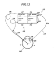
- Figs. 12 to 15 show a fifth embodiment of this invention.
- a vitrectomy apparatus includes an external means 212, an infusion instrument 213 according to this invention and a cutter 214.
- the external means 212 is composed of an actuating unit 217 and a suction unit 218.
- the cutter 214 is equiped with a motor (not shown) so as to cut the vitreous body 3 by its inner blade means (not shown).
- a suction passage is placed in the cutter 214 and connected by way of a suction pipe 219 to the suction unit 218.
- the motor is connected through an electric cable 220 to the actuating unit 217.
- the infusion instrument 213 includes a light source unit 215 equiped with a light source 270 therein, an infusion means 221 and two light transmitting means 222 as shown in Figs. 12 and 13.
- the infusion means 221 has a T-shape in section of pipe-like first member 223, a pipe-like second member 224 and an insertion member 225.
- the second member 224 is preferably a tube made of a resilient material such as a silicon tube.
- a joint portion 223a of the first member 223 is inserted. into a side wall 215a of the light source unit 215.
- the two light transmitting means 222 are set at their input end 226 in the joint portion 223a.
- Both input ends 226 face toward the light source 270 of the light source unit 215.
- a relay lens 280 is placed between the light source 270 and the input ends 226.
- An image from the light source 270 is projected at the input ends 226 by the relay lens 280.
- the light from the light source unit 215 is transmitted through the two transmitting means 222 each having no joint portion.
- the light transmitting means 222 are preferably optical fibers made of a glass or plastics.
- the two light transmitting means 222 are arranged within the first member 223 and the second member 224.
- the input ends 226 of the light transmitting means 222 are arranged side by side in the joint portion 223a of the first member 223 as best shown in Fig. 14. They are freely placed within the second member 224 as best shown in Fig. 13.
- the two light transmitting means 222 substantially do not affect the resiliency or flexibility of the second member 224.
- the connecting portion 223b of the first member 223 is connected by way of a connecting tube 227 to the infusion unit 216 as shown in Figs. 12 and 13.
- the connecting portion 223c of the first member 223 is inserted into one end of the second member 224.
- the insertion member 225 is located at the other end of the second member 224.
- the insertion end 228 of the insertion member 225 has an inclined end surface so as to be easily inserted into the scleral 7.
- the insertion member 225 is inserted into the other end of the second member 224 so as to be connected tightly to both the output ends 229 of the light transmitting means 222.
- the insertion end 228 is cylindrical as best shown in Fig. 15.
- the insertion end 228 is preferably made of a transparent material such as plastics and has substantially the same refractive index of the light transmitting means 222.
- the outer surface of the insertion end 228 is coated with a material having a relatively small refractive index compared with a refractive index of a material of the insertion end 228. Therefore, the light is prevented from reflecting out of the outer surface of the insertion end 228 when it comes from the light transmitting means 222.
- the light coming through the insertion end 228, can reach the inside of the eyeball 290 without loss.
- the insertion end 228 is partly surrounded by a tube 230 such as an infusion cannula having at its end a flange portion 230a made of an opaque material such as a metal for shielding the light.
- a tube 230 such as an infusion cannula having at its end a flange portion 230a made of an opaque material such as a metal for shielding the light.
- Four recesses 231 are formed in the flange portion 230a as shown in Fig. 15 for hooking strands or threads when the tube 230 is sutured to the scleral 7 of the eyeball 290.
- the infusion passage 232 for carrying the intraocular irrigating solusions from the infusion unit 216 into the eyeball 290 extends through the connecting tube 227, the first and second members 223, 224 and the insertion end 228.
- the scleral 7 is incised at two portions thereof in such a manner that the cutter 214 and the insertion end 228 of the infusion means 221 can be inserted into the eyeball 290 therethrough. If desired, a further portion of the scleral 7 is incised for forcepts and so on.
- the flange poriton 230a is fixed to the scleral 7 by the threads or strands sutured thereto.
- the light source 270 of the light source unit 215 is switched on to illuminate the inside of the eyeball 290 after the light therefrom is effectively transmitted through the two light transmitting means 222 and the insertion end 228.
- An opaque area of the vitreous body is cut by the cutter 214.
- the infusion unit 216 is actuated so as to infuse the intraocular irrigating solusions through the infusion passage 232 and the insertion end 228 into the eyeball 290.
- the suction unit 218 is actuated so as to suck both the cut portion and the intraocular irrigating solusions through the cutter 214 and the pipe 219.
- the vitreous cavity is filled with the intraocular irrigating solusions thereby to maintain a predetermined intraocular pressure therein.
- the insertion end 228 and the cutter 214 are drawn out and then the incised portions are sutured.
- No cover for the two light transmitting means 222 is additionally required because they are covered by the first and second members 223, 224.
- the insertion end 228 functions to infuse the intraocular irrigating solusions into the eyeball 290 and constitutes an extending portion of the light transmitting means 222 so as to transmit the light.
- the light transmitting means 222 are not inserted into the eyeball 290.
- Figs. 16 to 20 show a sixth embodiment of this invention which is substantially the same as the fifth embodiment of Figs. 12 to 15 except two light transmitting means 322 and a joint portion 352 of an insertion member 328 constituting an extending portion thereof.
- the same references designate the same or corresponding members or parts.
- two input ends 126 of the two light transmitting means 322 are connected to a further single light transmitting means 400.
- Two output ends 329 of the two light transmitting means 322 are joined to one end of the insertion member 328.
- the sectional area of the insertion member 328 can be set relatively small as compared with that of the prior art of Fig. 22 because the sectional area of both the optical fiber bundles and the cover thereof can be eliminated. Thus, when the insertion member 328 is drawn out, collapse of the eye can be avoided.
- the insertion member 328 is set small in size and light in weight, it can be directly sutured to the eyeball 390 whereby it is not necessary to support the infusion means 321 by a hand during operation.
- the output end of the insertion member 328 can be apart from the eyegrounds if its length is set short. Thus, a wide area on the eyegrounds can be illuminated so that the operations become easy.
- the two light transmitting means 322 are placed in longitudinal grooves 324a formed in an inner wall of the second member 324.
- the output ends 329 of the light transmitting means 322 fixedly extend into the insertion member 328 as shown in Figs. 19 and 20. Therefore, the relative position of the light transmitting means 322 to the insertion member 328 is fixed so as to transmit precisely the light into the eyeball.
- a flange portion 330a of a tube 330 such as an infusion cannula is substantially the same as the flange portion 230a of the tube 230 in Fig. 13.
- the input ends 326 of the light transmitting means 322 are arranged side by side in the first member 323 and connected tightly to the light transmitting means 400 of a large diameter by way of a connector 410.
- the light transmitting means 400 is connected to the light source unit 315.
- the light from-the light source 370 comes into the light transmitting means 400 by a lens 380.
- the light transmitting means 222 or 322 may be composed of three divided parts or more.
Landscapes
- Health & Medical Sciences (AREA)
- Ophthalmology & Optometry (AREA)
- Heart & Thoracic Surgery (AREA)
- Surgery (AREA)
- Engineering & Computer Science (AREA)
- Biomedical Technology (AREA)
- Nuclear Medicine, Radiotherapy & Molecular Imaging (AREA)
- Vascular Medicine (AREA)
- Life Sciences & Earth Sciences (AREA)
- Animal Behavior & Ethology (AREA)
- General Health & Medical Sciences (AREA)
- Public Health (AREA)
- Veterinary Medicine (AREA)
- Infusion, Injection, And Reservoir Apparatuses (AREA)
Abstract
Description
- This invention relates to pre-coated metal sheet suitable for use in the manufacture of bakeware and other products intended for use at high temperatures, being metal sheet which is provided with a coated finish before the sheet is used in the manufacture of such products.
- Such pre-coated metal sheet is used in the production of bakeware and other products by various manufacturing methods including: pressing; stamping; roll-forming and deep drawing. It avoids the necessity of applying a coated finish to the product after the manufacturing process which for some products can present difficulties both in the application of a coated finish and in the obtaining of an acceptable finish.
- Hitherto the pre-coated metal sheet which has been produced for use in the manufacture of bakeware and other products intended for use at high temperatures has had a plain finish; it has not had patterns, printing or other surface decoration on it. The present invention provides pre-coated metal sheet which has a surface decoration.
- According to the present invention there is provided a process of producing pre-coated metal sheet having a surface decoration and suitable for use in the manufacture of bakeware and other products intended for use. at high temperatures, which process comprises the steps of cleaning a raw metal sheet, applying to at scleral 7p of the eyeball 3p at a distance of about 4 mm from the limbus cornea 6p. The cutter 4p has a passage for the suction purpose therein. The tool 5p has an infusion tube 8p and a plurality of
optical fibers 9p for the illumination purpose as shown in Fig. 22. - In operation, the cutter 4p and the tool 5p are held by hands, respectively. While the light from the
optical fibers 9p illuminates the inside of the eyeball 3p, an opaque portion of thevitreous body 10p is cut by the cutter 4p. At the same time, the intraocular irrigating solusions is infused into the eyeball while the cut portion is sucked through the passage of the cutter 4p to the outside of the eyeball 3p. A predetermined intraocular pressure in the eyeball 3p can be maintained by the intraocular irrigating solutions.. - In the conventional infusion instrument, however, the sectional area of the tool 5p must be large because the plural
optical fibers 9p are arranged around the infusion tube 8p. Thus, collapse of the eye is apt to take place when the tool 5p is drawn out from the eyeball 3p. - If the tool 5p is set small in section, then the inside of the eyeball is not illuminated to a desired degree, and a sufficient volume of intraocular irrigating solusions does not flow through the infusion tube 8p.
- The object of this invention is to provide an infusion instrument for use in vitrectomy in which the inside of an eyeball can be sufficiently illuminated and collapse of the eye can be avoided.
- According to this invention, an infusion instrument comprises an infusion means for supplying intraocular irrigating solusions through an input end thereof, an infusion passage thereof and an insertion end thereof into an eyeball, an illumination unit including a light source for illuminating an inside portion of the eyeball, and a light transmitting means having a first end connected to the light source and a second end for transmitting a light from the light source to the eyeball. At least the second end of the light transmitting means is arranged in the infusion passage so as to illuminate the inside portion of the eyeball. For example, a mojority of the light transmitting means is placed within the infusion passage of the infusion means. Only an end of the light transmitting means may be placed near or at a place where the light from the light source reaches the inside of the eyeball through the insertion end within the infusion means.
- Preferalbly, the light transmitting means is a plastic optical fiber.
-
- Fig. 1 is an explanatory view showing an operation condition in which a pipe-like infusion instrument and its related parts according to a first embodiment of this invention are used in vitrectomy;
- Fig. 2 is an enlarged sectional view showing an infusion means in the infusion instrument shown in Fig. 1;
- Fig. 3 is a sectional view taken along the line A-A of Fig. 2;
- Fig. 4 is an explanatory view showing an operation condition in which an infusion instrument according to a second embodiment of this invention is used in vitrectomy;
- Fig. 5 is a sectional view showing a portion of an infusion means and an illumination unit used in the infusion instrument shown in Fig. 4;
- Fig. 6 is a sectional view taken along the line B-B of Fig. 5;
- Fig. 7 is a bottom view showing an insertion member in the infusion instrument shown in Fig. 4;
- Fig. 8 is an explanatory view showing an operation condition in which an infusion instrument according to a third embodiment of this invention is used in vitrectomy;
- Fig. 9 is a sectional view showing a portion of an infusion means in the infusion instrument shown in Fig. 8 which is sutured to an eyeball;
- Fig. 10 is a sectional view taken along the line A-A of Fig. 9;
- Fig. 11 is a sectional view showing an essential portion of an infusion means according to a fourth embodiment of this invention, corresponding to Fig. 9;
- Fig. 12 is an explanatory view showing an operation condition in which an infusion instrument according to a fifth embodiment of this invention is used in vitrectomy;
- Fig. 13 is a sectional view showing an infusion means and its related members used in the infusion instrument shown in Fig. 12;
- Fig. 14 is a sectional view taken along the line A-A of Fig. 13;
- Fig. 15 is a sectional view taken along the line B-B of Fig. 13;
- Fig. 16 is a sectional view showing an infusion means and its related members according to a sixth embodiment of this invention;
- Fig. 17 is a sectional view taken along the line C-C of Fig. 15 16;
- Fig. 18 is a sectional view taken along the line D-D of Fig. 16;
- Fig. 19 is a sectional view taken along the line E-E of Fig. 16; and
- Fig. 20 is a perspective view showing a portion of the infusion means shown in Fig. 16, with some parts cut away.
- Figs. 1 to 3 show a first embodiment of this invention.
- A vitrectomy apparatus includes an
external means 12, aninfusion instrument 13 according to this invention and acutter 14. Theexternal means 12 is composed of an actuatingunit 17 and asuction unit 18. Thecutter 14 is equiped with a motor (not shown) for cutting thevitreous body 3 by its inner blade means (not shown). A suction passage is placed in thecutter 14 and connected by way of asuction pipe 19 to thesuction unit 18. The motor is connected through anelectric cable 20 to the actuatingunit 17. - The
infusion instrument 13 includes alight source unit 15 equiped with a light source therein, an infusion means 21, a first light transmitting means 25 and a second light transmitting means 28 as shown in Figs. 1 and 2. - The infusion means 21 has a
first member 22, a pipe-likesecond member 23, a pipe-like insertion member 24 and aninfusion unit 16. - The first light transmitting means 25 is placed within the
second member 23 of the infusion means 21 between thefirst member 22 and theinsertion member 24. Preferably, the first light transmitting means 25 is an optical fiber made of a glass or plastics having a good flexibility or resiliency. The pipe-likesecond member 23 is also made of a flexible or resilient material. If thesecond member 23 and the first light transmitting means 25 are flexible or resilient, aneyeball 90 does not receive an overpressure due to their spring force when the infusion means 21 is sutured to theeyeball 90 in operation. - The
first member 22 has three parts: a small-diameter joint portion 22a, a relatively large-diameter connecting portion 22b connected to theinfusion unit 16 and a further relatively large-diameterjoint portion 22c inserted into one end of thesecond member 23. Aninput end 26 of the first light transmitting means 25 is inserted into thejoint portion 22a. - The
joint portion 22a is to be joined to aconnector 27 into which anoutput end 29 of the second light transmittingmeans 28 is inserted. The second light transmitting means 28 is preferably an optical fiber made of a glass or plastics and has a larger diameter than that of the first light transmitting means 25. Thus, even if the first and second light transmitting means 25, 28 are misaligned to some minor degree, a light can be properly transmitted therebetween. An input end of the second light transmitting means 28 is connected to thelight source unit 15. - An
insertion member 24 such as an infusion cannula is inserted into the other end of thesecond member 23. An insertion end 24a of theinsertion member 24 has an inclined end surface so that it can be easily inserted into theeyeball 90. The inner diameter of theinsertion end 24a is smaller than that of thesecond member 23 and larger than the outer diameter of the first light transmitting means 25. - The first light transmitting means 25 extends from the
first member 22 through thesecond member 23 to theinsertion member 24. The first light transmitting means 25 is fixed at itsoutput end 30 to theinsertion member 24. That is, the first light transmitting means 25 is fixed to an inner wall of theinsertion member 24 by means of abolt 31 fixed to theinsertion member 24 as best shown in Fig. 3. - An
infusion passage 32 for the intraocular irrigating solusions which is a transparent liquid extends from the interior of thefirst member 22 through the interior of thesecond member 23 to the interior of theinsertion member 24. Although at least theoutput end 30 of the first light transmitting means 25 should be placed within theinfusion passage 32, a majority of the first light transmitting means 25 is preferably positioned within theinfusion passage 32. - The
insertion member 24 has twoflange portions recesses 35 are formed in theflange portions scleral 7 of theeyeball 90. - In operation, the
scleral 7 is incised at two portions thereof in such a manner that thecutter 14 and theinsertion member 24 can be inserted into the eyeball therethrough. If desired, a further portion of thescleral 7 is incised for forcepts and so on. Theflange portions scleral 7 by the threads or strands sutured thereto. - The light source in the
light source unit 15 is switched on to illuminate the inside of theeyeball 90 by way of the first and second light transmitting means 25, 28. An opaque portion of the vitreous body is cut by thecutter 14. Theinfusion unit 16 is actuated so as to infuse the intraocular irrigating solusions through theinfusion passage 32 and theinsertion member 24 into theeyeball 90. Also, thesuction unit 18 is actuated so as to suck both the cut portion and the intraocular irrigating solusions. - After the cutting and suction, the vitreous cavity is filled with the intraocular irrigating solusions thereby to obtain a predetermined intraocular pressure therein.
- At the end of the operation, the
insertion member 24 and thecutter 14 are drawn out and then the incised portions are sutured. - No cover for the first light transmitting means 25 is additionally required because the first light transmitting means 25 is placed within the
infusion passage 32 and both thesecond member 23 and theinsertion member 24 forming an extending portion of theinfusion passage 32 function as a cover for the first light transmitting means 25. Thus, the sectional area of theinsertion end 24a can be set relatively small. As a result, collapse of the eye can be avoided after theinsertion end 24a is drawn out from theeyeball 90. In addition, theinsertion member 24 can be light in weight and small in size so that it can be sutured directly onto theeyeball 90. Also, it is not necessary to support the infusion means 21. - While the intraocular irrigating solutions flow through the
infusion passage 32, even if a strong light from the light source reaches the first light transmitting means 25, the intraocular irrigating solutions function as a coolant whereby deformation of the first light transmitting means 25 can be avoided. - Figs. 4 to 7 show a second embodiment of this invention which is substantially the same as the first embodiment of Figs. 1 to 3 except the construction of infusion means 51. The same references designate the same or corresponding members or parts.
- In the second embodiment of Figs. 4 to 7, light is transmitted through a single light transmitting means 55 having no joint portion. The light transmitting means 55 is preferably an optical fiber made of a glass or plastics.
- The infusion means 51 has a T-shape in section of
first member 52, a tube-likesecond member 53, and aninsertion member 54 such as an infusion cannula. A connectingportion 52a of thefirst member 52 is inserted into a side wall of thelight source unit 15. An input end 56 of the light transmitting means 55 is inserted into the connectingportion 52a and faces toward thelight source 70 within thelight source unit 15. Arelay lens 80 is disposed between thelight source 70 and theinput end 56 of the light transmitting means 55. An image from thelight source 70 is projected at theinput end 56 thereof. - A connecting
portion 52b of thefirst member 52 is connected by way of a connectingtube 65 to theinfusion unit 16. Ajoint portion 52c of thefirst member 52 is inserted into one end of thesecond member 53. - The
insertion member 54 is inserted into the other end of thesecond member 53. Aninsertion end 54a of theinsertion member 54 has an inclined end surface so as to be easily inserted into thescleral 7. The inner surface of theinsertion member 54 has a specular reflection of an excellent light reflection rate. Theoutput end 57 of the light transmitting means 55 is positioned within theinsertion memberd 54 and fixed thereto as shown in Fig. 6. The outer diameter of theinsertion end 54a is smaller than that of thesecond member 53 as shown in Fig. 5. Theinsertion member 54 has two extendingportions recesses 65 for hooking strands or threads as shown in Fig. 7. - The
first member 52, thesecond member 53 and theinsertion member 54 are made of a synthetic resin or the like. Thesecond member 53 is preferably transparent and resilient. - An
infusion passage 62 has such a length that it can be arranged from thefirst member 52 through thesecond member 53 to theinsertion member 54. A majority of the light transmitting means 55 is positioned within theinfusion passage 62. - The operation of the second embodiment will not be described because it is substantially the same as that of the first embodiment.
- Figs. 8 to 10 show a third embodiment of this invention.
- A vitrectomy apparatus includes an
external means 110, aninfusion instrument 111 according to this invention and acutter 112. The external means 110 is composed of anactuating unit 115 and asuction unit 116. Thecutter 112 is equiped with a motor (not shown) so as to cut thevitreous body 3 by its inner blade means (not shown). A suction passage is placed in thecutter 112 and connected by way of asuction pipe 117 to thesuction unit 116. The motor is connected through anelectric cable 118 to theactuating unit 115. - The
infusion instrument 111 includes alight source unit 113 =quiped with a light source therein, an infusion means 119 and a Light transmitting means 124 as shown in Figs. 8 to 10. - The infusion means 119 has a tube-like
first member 120, a pipe-likesecond member 121, aninfusion pipe 122 and an infusion unit 114. - The resilient or
flexible infusion pipe 122 connects one end of thefirst member 120 to the infusion unit 114 and preferably made of a transparent synthetic resin. A L-shape in section ofinfusion passage 123 is formed in thefirst member 120 and thesecond member 121. Theoutput end 124a of the light transmitting means 124 is inserted into one end of thesecond member 121 and positioned within theinfusion passage 123 near aninner wall 126a of aninsertion end 126 thereof. The light transmitting means 124 is preferably an optical fiber made of a glass or plastics having a good resiliency. The input end of the light transmitting means 124 is connected to the light source unit -113. - The
insertion end 126 of thesecond member 121 has an inclined end surface so as to be easily inserted into theeyeball 125. The inner diameter of theinsertion end 126 is smaller than that of theinfusion passage 123 of thesecond member 121 and substantially corresponds to the outer diameter of the light transmitting means 124. - The
inner surface 126a of theinsertion end 126 of thesecond member 121 has.a specular reflection so that the light from theoutput end 124a of the light transmitting means 124 can be reflected at a high rate. For example, an aluminum-deposited layer may be formed thereon. Thesecond member 121 funcions as both an infusion passage and a light guide passage. - The
second member 121 has two extendingportions recesses 129 for hooking strands or threads when thesecond member 121 is sutured onto thescleral 7 of theeyeball 125. - In operation, the
scleral 7 is incised at a distance of about 4 mm from a limbus cornea in such a manner that thecutter 112 and the infusion means 119 can be separateley inserted into theeyeball 125 therethrough. If desired, thescleral 7 is further incised for forcepts and so on. The extendingportions scleral 7 by the threads or strands sutured thereto. - The light source in the
light source unit 113 is switched on to transmit a light by way of the light transmitting means 124 to thesecond member 121. The light from theoutput end 124a of the light transmitting means 124 is reflected by theinner wall 126a of theinsertion end 126 so as to illuminate thevitreous body 3 as shown by dotted lines in Fig. 9. An opaque area of thevitreous body 3 is cut by thecutter 112 under illumination from the light transmitting means 124. At the same time, the cut portion is sucked through thecutter 112 and thepipe 117 into thesuction unit 116. Also, the intraocular irrigating solusions from the infusion unit 114 is infused through theinfusion pipe 122 and theinfusion passage 123 into theeyeball 125. - After the cutting and suction, the vitreous cavity is filled with the intraocular irrigating solusions thereby to obtain a predetermined intraocular pressure therein.
- At the end of the operation, the
insertion end 126 and thecutter 112 are drawn out and then the incised portions are sutured. - During the operation, the inside of the
eyeball 125 is illuminated enough to obtain a visual field therein for operation. The diameter of the light transmitting means 124 can be large to such a degree that the intraocular irrigating solusions can smoothly flow through theinfusion passage 123. Also, as theinner wall 126a of theinsertion end 126 has a good reflection, the light from theoutput end 124a can be effectively transmitted to the inside of theeyeball 125 without loss. - The light transmitting means 124 itself is not inserted into the
eyeball 125. Theoutput end 124a of the light transmitting means 124 is positioned within thesecond member 121 at or near a place where the light from the light source reaches the inside of theeyeball 125 through theinsertion end 126 within theinfusion passage 119. The outer diameter of theinsertion end 126 can be set relatively large without regard to a size of the light transmitting means 124. The inner diameter of theinsertion end 126 can be set large to such a degree that a predetermined volume of intraocular irrigating solusions can be infused into theeyeball 125. - When the
insertion end 126 is drawn out, collapse of the eye can be avoided because the outer diameter of theinsertion end 126 is small. - Fig.11 shows a fourth embodiment of this invention which is substantially the same as the third embodiment of Figs. 8 to 10 except the construction of the infusion means. The same references designate the same or corresponding members or parts.
- In the fourth embodiment of Fig. 11, an infusion means 139 has a pipe-like
first member 140 and asecond member 141 connected thereto. Thefirst member 140 is similar in shape to thefirst member 120 of Fig. 9. Thesecond member 141 differs in form from thesecond member 121 of Fig. 9. A L-shape in section ofinfusion passage 143 is formed in the first and second members 140,141. - The inner diameter of the
infusion passage 143 of thesecond member 141 is the same as that of the insertion end 146. Anoutput end 144a of the light transmitting means 144 is inserted into one end of thesecond member 141. The light transmitting means 144 is preferably an optical fiber made of a glass or plastics. Theoutput end 144a thereof constitutes an extending portion of theinfusion passage 143 and does not project into theinfusion passage 143. - The
second member 141 and the insertion end 146 have a continuous inner wall of a good reflection as in the third embodiment of Fig. 9. - Two extending
portions 147, 148 such as an infusion cannula are formed at a periphery of thesecond member 141. - The infusion means 139 of Fig. 11 is used like in the infusion means 119 of Figs. 8 to 10.
- Figs. 12 to 15 show a fifth embodiment of this invention.
- A vitrectomy apparatus includes an
external means 212, aninfusion instrument 213 according to this invention and acutter 214. The external means 212 is composed of anactuating unit 217 and asuction unit 218. Thecutter 214 is equiped with a motor (not shown) so as to cut thevitreous body 3 by its inner blade means (not shown). A suction passage is placed in thecutter 214 and connected by way of asuction pipe 219 to thesuction unit 218. The motor is connected through anelectric cable 220 to theactuating unit 217. - The
infusion instrument 213 includes alight source unit 215 equiped with alight source 270 therein, an infusion means 221 and two light transmitting means 222 as shown in Figs. 12 and 13. The infusion means 221 has a T-shape in section of pipe-likefirst member 223, a pipe-likesecond member 224 and aninsertion member 225. Thesecond member 224 is preferably a tube made of a resilient material such as a silicon tube. - A joint portion 223a of the
first member 223 is inserted. into aside wall 215a of thelight source unit 215. The two light transmitting means 222 are set at theirinput end 226 in the joint portion 223a. - Both input ends 226 face toward the
light source 270 of thelight source unit 215. Arelay lens 280 is placed between thelight source 270 and the input ends 226. An image from thelight source 270 is projected at the input ends 226 by therelay lens 280. The light from thelight source unit 215 is transmitted through the two transmitting means 222 each having no joint portion. The light transmitting means 222 are preferably optical fibers made of a glass or plastics. - The two light transmitting means 222 are arranged within the
first member 223 and thesecond member 224. The input ends 226 of the light transmitting means 222 are arranged side by side in the joint portion 223a of thefirst member 223 as best shown in Fig. 14. They are freely placed within thesecond member 224 as best shown in Fig. 13. Thus, the two light transmitting means 222 substantially do not affect the resiliency or flexibility of thesecond member 224. - The connecting
portion 223b of thefirst member 223 is connected by way of a connectingtube 227 to theinfusion unit 216 as shown in Figs. 12 and 13. The connectingportion 223c of thefirst member 223 is inserted into one end of thesecond member 224. - The
insertion member 225 is located at the other end of thesecond member 224. Theinsertion end 228 of theinsertion member 225 has an inclined end surface so as to be easily inserted into thescleral 7. - The
insertion member 225 is inserted into the other end of thesecond member 224 so as to be connected tightly to both the output ends 229 of the light transmitting means 222. Theinsertion end 228 is cylindrical as best shown in Fig. 15. Theinsertion end 228 is preferably made of a transparent material such as plastics and has substantially the same refractive index of the light transmitting means 222. The outer surface of theinsertion end 228 is coated with a material having a relatively small refractive index compared with a refractive index of a material of theinsertion end 228. Therefore, the light is prevented from reflecting out of the outer surface of theinsertion end 228 when it comes from the light transmitting means 222. Thus, the light coming through theinsertion end 228, can reach the inside of theeyeball 290 without loss. - The
insertion end 228 is partly surrounded by atube 230 such as an infusion cannula having at its end aflange portion 230a made of an opaque material such as a metal for shielding the light. Fourrecesses 231 are formed in theflange portion 230a as shown in Fig. 15 for hooking strands or threads when thetube 230 is sutured to thescleral 7 of theeyeball 290. - The
infusion passage 232 for carrying the intraocular irrigating solusions from theinfusion unit 216 into theeyeball 290 extends through the connectingtube 227, the first andsecond members insertion end 228. - In operation, the
scleral 7 is incised at two portions thereof in such a manner that thecutter 214 and theinsertion end 228 of the infusion means 221 can be inserted into theeyeball 290 therethrough. If desired, a further portion of thescleral 7 is incised for forcepts and so on. Theflange poriton 230a is fixed to thescleral 7 by the threads or strands sutured thereto. - The
light source 270 of thelight source unit 215 is switched on to illuminate the inside of theeyeball 290 after the light therefrom is effectively transmitted through the two light transmitting means 222 and theinsertion end 228. An opaque area of the vitreous body is cut by thecutter 214. Theinfusion unit 216 is actuated so as to infuse the intraocular irrigating solusions through theinfusion passage 232 and theinsertion end 228 into theeyeball 290. Also, thesuction unit 218 is actuated so as to suck both the cut portion and the intraocular irrigating solusions through thecutter 214 and thepipe 219. - After the cutting and suction, the vitreous cavity is filled with the intraocular irrigating solusions thereby to maintain a predetermined intraocular pressure therein.
- At the end of the operation, the
insertion end 228 and thecutter 214 are drawn out and then the incised portions are sutured. - No cover for the two light transmitting means 222 is additionally required because they are covered by the first and
second members insertion end 228 functions to infuse the intraocular irrigating solusions into theeyeball 290 and constitutes an extending portion of the light transmitting means 222 so as to transmit the light. The light transmitting means 222 are not inserted into theeyeball 290. - Figs. 16 to 20 show a sixth embodiment of this invention which is substantially the same as the fifth embodiment of Figs. 12 to 15 except two light transmitting means 322 and a
joint portion 352 of aninsertion member 328 constituting an extending portion thereof. The same references designate the same or corresponding members or parts. - In the sixth embodiment of Figs. 16 to 20, two input ends 126 of the two light transmitting means 322 are connected to a further single light transmitting means 400. Two output ends 329 of the two light transmitting means 322 are joined to one end of the
insertion member 328. The sectional area of theinsertion member 328 can be set relatively small as compared with that of the prior art of Fig. 22 because the sectional area of both the optical fiber bundles and the cover thereof can be eliminated. Thus, when theinsertion member 328 is drawn out, collapse of the eye can be avoided. In addition, if theinsertion member 328 is set small in size and light in weight, it can be directly sutured to theeyeball 390 whereby it is not necessary to support the infusion means 321 by a hand during operation. - The output end of the
insertion member 328 can be apart from the eyegrounds if its length is set short. Thus, a wide area on the eyegrounds can be illuminated so that the operations become easy. - As shown in Fig. 18, the two light transmitting means 322 are placed in longitudinal grooves 324a formed in an inner wall of the
second member 324. The output ends 329 of the light transmitting means 322 fixedly extend into theinsertion member 328 as shown in Figs. 19 and 20. Therefore, the relative position of the light transmitting means 322 to theinsertion member 328 is fixed so as to transmit precisely the light into the eyeball. - A
flange portion 330a of atube 330 such as an infusion cannula is substantially the same as theflange portion 230a of thetube 230 in Fig. 13. - The input ends 326 of the light transmitting means 322 are arranged side by side in the
first member 323 and connected tightly to the light transmitting means 400 of a large diameter by way of aconnector 410. The light transmitting means 400 is connected to the light source unit 315. The light from-thelight source 370 comes into the light transmitting means 400 by alens 380. - This invention is not limited to the above-stated embodiments. For instance, the light transmitting means 222 or 322 may be composed of three divided parts or more.
Claims (13)
Applications Claiming Priority (6)
| Application Number | Priority Date | Filing Date | Title |
|---|---|---|---|
| JP92343/85 | 1985-05-01 | ||
| JP60092344A JPS61253057A (en) | 1985-05-01 | 1985-05-01 | Inffuser with illumination |
| JP60092343A JPS61253056A (en) | 1985-05-01 | 1985-05-01 | Illuminated perfusion device |
| JP92344/85 | 1985-05-01 | ||
| JP60132958A JPS61290950A (en) | 1985-06-20 | 1985-06-20 | Perfusion device with lighting function |
| JP132958/85 | 1985-06-20 |
Publications (3)
| Publication Number | Publication Date |
|---|---|
| EP0201280A2 true EP0201280A2 (en) | 1986-11-12 |
| EP0201280A3 EP0201280A3 (en) | 1987-04-15 |
| EP0201280B1 EP0201280B1 (en) | 1990-07-25 |
Family
ID=27307011
Family Applications (1)
| Application Number | Title | Priority Date | Filing Date |
|---|---|---|---|
| EP86303306A Expired - Lifetime EP0201280B1 (en) | 1985-05-01 | 1986-05-01 | Infusion instrument |
Country Status (3)
| Country | Link |
|---|---|
| US (1) | US4820264A (en) |
| EP (1) | EP0201280B1 (en) |
| DE (1) | DE3672888D1 (en) |
Cited By (6)
| Publication number | Priority date | Publication date | Assignee | Title |
|---|---|---|---|---|
| DE3822011A1 (en) * | 1988-06-30 | 1990-01-11 | Geuder Hans Gmbh | OpHthalmic surgical instrument for aspirating lens residues and laser phacocataract system with two such instruments |
| EP0501034A1 (en) * | 1991-01-30 | 1992-09-02 | CeramOptec GmbH | Illuminated leading probe device |
| WO2007073802A1 (en) * | 2005-12-15 | 2007-07-05 | Carl Zeiss Surgical Gmbh | Method for illuminating the site of an operation, illumination device and surgical instrument |
| WO2007133267A1 (en) * | 2005-12-16 | 2007-11-22 | Alcon, Inc. | Illuminated infusion cannula |
| ES2539523A1 (en) * | 2013-12-31 | 2015-07-01 | Fundación Tekniker | Vitreoctomy device |
| DE102011111285B4 (en) | 2011-08-26 | 2019-02-21 | Geuder Aktiengesellschaft | Device for introducing light and fluid into a human or animal body and method for producing such a device |
Families Citing this family (42)
| Publication number | Priority date | Publication date | Assignee | Title |
|---|---|---|---|---|
| US5066276A (en) * | 1988-06-21 | 1991-11-19 | Alcon Laboratories, Inc. | Method and apparatus for injecting viscous fluid into the eye to lift pre-retinal and post-retinal membrane with linear pressure control |
| US5120307A (en) * | 1988-06-21 | 1992-06-09 | Alcon Laboratories, Inc. | Method for injecting viscous fluid into the eye to life retinal membrane |
| US5203353A (en) * | 1989-10-24 | 1993-04-20 | Surgical Technologies, Inc. | Method of penetrating and working in the vitreous humor of the eye |
| US5217454A (en) * | 1991-08-01 | 1993-06-08 | Angiolaz, Incorporated | Laser delivery catheter |
| WO1994012131A1 (en) * | 1992-11-20 | 1994-06-09 | Shinseiro Okamoto | Cornea operating method and apparatus |
| US5425730A (en) * | 1994-02-16 | 1995-06-20 | Luloh; K. P. | Illumination cannula system for vitreous surgery |
| US5545153A (en) * | 1994-08-15 | 1996-08-13 | A.V.I. - Advanced Visual Instruments, Inc. | Adjustable miniature panoramic illumination and infusion system for retinal surgery |
| US5725514A (en) * | 1994-08-15 | 1998-03-10 | A.V.I. - Advanced Visual Instruments, Inc. | Adjustable miniature panoramic illumination and infusion system for retinal surgery |
| US5630809A (en) * | 1994-12-19 | 1997-05-20 | Connor; Christopher S. | Intraocular slit illuminator and method therefor |
| GB9518888D0 (en) * | 1995-09-15 | 1995-11-15 | Byrne Phillip O | Device and method for transcutaneous surgery |
| US7655002B2 (en) * | 1996-03-21 | 2010-02-02 | Second Sight Laser Technologies, Inc. | Lenticular refractive surgery of presbyopia, other refractive errors, and cataract retardation |
| US5984914A (en) * | 1998-07-03 | 1999-11-16 | Cumming; J. Stuart | Apparatus and method for corneal keratotomy |
| US6162210A (en) * | 1998-08-06 | 2000-12-19 | Shadduck; John H. | Laser mediated treatments for presbyopia and hyperopia |
| US20030169603A1 (en) * | 2002-03-05 | 2003-09-11 | Luloh K. Peter | Apparatus and method for illuminating a field of view within an eye |
| WO2006124918A2 (en) * | 2005-05-18 | 2006-11-23 | Insight Instruments, Inc. | Self inserting intraocular light |
| US9375349B2 (en) | 2006-01-20 | 2016-06-28 | Lensar, Llc | System and method for providing laser shot patterns to the lens of an eye |
| US8262646B2 (en) | 2006-01-20 | 2012-09-11 | Lensar, Inc. | System and method for providing the shaped structural weakening of the human lens with a laser |
| US9545338B2 (en) | 2006-01-20 | 2017-01-17 | Lensar, Llc. | System and method for improving the accommodative amplitude and increasing the refractive power of the human lens with a laser |
| US9889043B2 (en) | 2006-01-20 | 2018-02-13 | Lensar, Inc. | System and apparatus for delivering a laser beam to the lens of an eye |
| US10842675B2 (en) | 2006-01-20 | 2020-11-24 | Lensar, Inc. | System and method for treating the structure of the human lens with a laser |
| US7654716B1 (en) | 2006-11-10 | 2010-02-02 | Doheny Eye Institute | Enhanced visualization illumination system |
| US20080177257A1 (en) * | 2007-01-23 | 2008-07-24 | Smith Ronald T | Thermally robust illumination probe tip |
| DE102007014634B3 (en) * | 2007-03-23 | 2008-12-11 | Karl-Heinz Bachmann | Instrument for the medical examination of narrow body canals |
| US20090163897A1 (en) * | 2007-12-19 | 2009-06-25 | Skinner Allen W | Illuminated Ophthalmic Instruments |
| US8480659B2 (en) | 2008-07-25 | 2013-07-09 | Lensar, Inc. | Method and system for removal and replacement of lens material from the lens of an eye |
| US8500723B2 (en) | 2008-07-25 | 2013-08-06 | Lensar, Inc. | Liquid filled index matching device for ophthalmic laser procedures |
| US20100318074A1 (en) * | 2009-06-10 | 2010-12-16 | Bruno Dacquay | Ophthalmic endoillumination using low-power laser light |
| US8465478B2 (en) | 2009-07-24 | 2013-06-18 | Lensar, Inc. | System and method for performing LADAR assisted procedures on the lens of an eye |
| US8617146B2 (en) | 2009-07-24 | 2013-12-31 | Lensar, Inc. | Laser system and method for correction of induced astigmatism |
| US8758332B2 (en) | 2009-07-24 | 2014-06-24 | Lensar, Inc. | Laser system and method for performing and sealing corneal incisions in the eye |
| US8382745B2 (en) | 2009-07-24 | 2013-02-26 | Lensar, Inc. | Laser system and method for astigmatic corrections in association with cataract treatment |
| US8343106B2 (en) | 2009-12-23 | 2013-01-01 | Alcon Research, Ltd. | Ophthalmic valved trocar vent |
| BR112012017771B1 (en) | 2009-12-23 | 2020-07-14 | Alcon Research, Llc | VALVE TROCART CANNULA |
| DE102010006035A1 (en) * | 2010-01-27 | 2011-07-28 | Paterok, Peter, Dr., 41061 | Applicator for use in photodynamic therapy |
| CN102843955A (en) | 2010-02-01 | 2012-12-26 | 雷萨公司 | Purkinjie image-based alignment of suction ring in ophthalmic applications |
| EP2568937B1 (en) * | 2010-05-13 | 2018-04-11 | Doheny Eye Institute | Self contained illuminated infusion cannula system |
| USD694890S1 (en) | 2010-10-15 | 2013-12-03 | Lensar, Inc. | Laser system for treatment of the eye |
| ES2937241T3 (en) | 2010-10-15 | 2023-03-27 | Lensar Inc | System and method of illumination controlled by scanning structures within an eye |
| USD695408S1 (en) | 2010-10-15 | 2013-12-10 | Lensar, Inc. | Laser system for treatment of the eye |
| US10463541B2 (en) | 2011-03-25 | 2019-11-05 | Lensar, Inc. | System and method for correcting astigmatism using multiple paired arcuate laser generated corneal incisions |
| US9393154B2 (en) | 2011-10-28 | 2016-07-19 | Raymond I Myers | Laser methods for creating an antioxidant sink in the crystalline lens for the maintenance of eye health and physiology and slowing presbyopia development |
| WO2018215954A1 (en) * | 2017-05-24 | 2018-11-29 | Novartis Ag | Illuminated infusion cannula |
Family Cites Families (12)
| Publication number | Priority date | Publication date | Assignee | Title |
|---|---|---|---|---|
| US3498286A (en) * | 1966-09-21 | 1970-03-03 | American Optical Corp | Catheters |
| US3659607A (en) * | 1968-09-16 | 1972-05-02 | Surgical Design Corp | Method for performing surgical procedures on the eye |
| US3821510A (en) * | 1973-02-22 | 1974-06-28 | H Muncheryan | Hand held laser instrumentation device |
| DE2456755A1 (en) * | 1974-11-30 | 1976-08-12 | Josef Heiss Fa | Ophthalmic vitrectomy instrument for single handed use - is designed to grind up and aspirate aqueous humour away from eye |
| US4269192A (en) * | 1977-12-02 | 1981-05-26 | Olympus Optical Co., Ltd. | Stabbing apparatus for diagnosis of living body |
| US4222375A (en) * | 1978-03-10 | 1980-09-16 | Miguel Martinez | In vivo illumination system utilizing a cannula with a conical opening allowing a snap-fit with a conical lens and an aperture for flow of fluids and utilizing a housing with a spherical lens for focusing light onto fiber optics |
| US4311138A (en) * | 1980-03-10 | 1982-01-19 | Sugarman Edward D | Illuminated hypodermic needle |
| US4331130A (en) * | 1980-06-27 | 1982-05-25 | Lewicky Andrew O | Securing device to the cornea to prevent anterior chamber prolapse |
| US4567882A (en) * | 1982-12-06 | 1986-02-04 | Vanderbilt University | Method for locating the illuminated tip of an endotracheal tube |
| IT1163169B (en) * | 1983-03-25 | 1987-04-08 | Sis Ter Spa | AUTOMATIC SUCTION AND PUMPING EQUIPMENT |
| US4551129A (en) * | 1983-04-08 | 1985-11-05 | Coleman D Jackson | Technique and apparatus for intraocular and microsurgery including lighter-irrigator hypodermic tube |
| US4596552A (en) * | 1983-06-10 | 1986-06-24 | Dlp Inc. | Cardioplegia cannula |
-
1986
- 1986-04-29 US US06/857,171 patent/US4820264A/en not_active Expired - Lifetime
- 1986-05-01 DE DE8686303306T patent/DE3672888D1/en not_active Expired - Lifetime
- 1986-05-01 EP EP86303306A patent/EP0201280B1/en not_active Expired - Lifetime
Cited By (13)
| Publication number | Priority date | Publication date | Assignee | Title |
|---|---|---|---|---|
| DE3822011A1 (en) * | 1988-06-30 | 1990-01-11 | Geuder Hans Gmbh | OpHthalmic surgical instrument for aspirating lens residues and laser phacocataract system with two such instruments |
| EP0501034A1 (en) * | 1991-01-30 | 1992-09-02 | CeramOptec GmbH | Illuminated leading probe device |
| WO2007073802A1 (en) * | 2005-12-15 | 2007-07-05 | Carl Zeiss Surgical Gmbh | Method for illuminating the site of an operation, illumination device and surgical instrument |
| AU2006343552B2 (en) * | 2005-12-16 | 2011-11-10 | Alcon Inc. | Illuminated infusion cannula |
| EP2215995A1 (en) * | 2005-12-16 | 2010-08-11 | Alcon, Inc. | Illuminated infusion and incision cannula |
| RU2419400C2 (en) * | 2005-12-16 | 2011-05-27 | Алькон, Инк. | Light-conducting infusion cannula |
| WO2007133267A1 (en) * | 2005-12-16 | 2007-11-22 | Alcon, Inc. | Illuminated infusion cannula |
| CN101365404B (en) * | 2005-12-16 | 2012-06-06 | 爱尔康公司 | Illuminated infusion cannula |
| CN102614045A (en) * | 2005-12-16 | 2012-08-01 | 爱尔康公司 | Illuminated infusion cannula |
| CN102614045B (en) * | 2005-12-16 | 2014-11-12 | 爱尔康公司 | Illuminated infusion cannula |
| DE102011111285B4 (en) | 2011-08-26 | 2019-02-21 | Geuder Aktiengesellschaft | Device for introducing light and fluid into a human or animal body and method for producing such a device |
| ES2539523A1 (en) * | 2013-12-31 | 2015-07-01 | Fundación Tekniker | Vitreoctomy device |
| WO2015101624A1 (en) * | 2013-12-31 | 2015-07-09 | Fundación Tekniker | Device for vitrectomy |
Also Published As
| Publication number | Publication date |
|---|---|
| EP0201280B1 (en) | 1990-07-25 |
| DE3672888D1 (en) | 1990-08-30 |
| EP0201280A3 (en) | 1987-04-15 |
| US4820264A (en) | 1989-04-11 |
Similar Documents
| Publication | Publication Date | Title |
|---|---|---|
| EP0201280A2 (en) | Infusion instrument | |
| US5558669A (en) | Fiber optic sleeve for surgical instruments | |
| EP0097934B1 (en) | A composite optical fiber and imaging catheter and method for producing the same | |
| US4551129A (en) | Technique and apparatus for intraocular and microsurgery including lighter-irrigator hypodermic tube | |
| US4671283A (en) | Forceps | |
| EP4120976B1 (en) | Laser vitrectomy and illumination probe | |
| CA2832502C (en) | Illuminated microsurgical instrument including optical fiber with beveled end face | |
| CA1233717A (en) | Ophthalmic surgical instrument with beveled tip and method for making said instrument | |
| US10675390B2 (en) | Combined coaxial and bimanual irrigation/aspiration apparatus | |
| US4807625A (en) | Membrane puncturing aspirator with drainage shield | |
| KR102003724B1 (en) | Illuminated suction apparatus | |
| US4850342A (en) | Hard endoscope of oblique view type | |
| CA3038472A1 (en) | Medical instrument with an integrated optical fiber | |
| EP0358392A2 (en) | Miniscope | |
| US20140210116A1 (en) | Illuminated surgical instrument | |
| CA2548735A1 (en) | Foldable intraocular lens and method of making | |
| CN104994793A (en) | Disposable capsulorhexis forceps | |
| EP0927373A2 (en) | An enhanced resolution image guide | |
| US6485499B1 (en) | Hard drive vitrectomy cutter | |
| WO1989003202A3 (en) | Method and apparatus for laser emulsification | |
| US11471242B1 (en) | Medical instruments with an integrated optical fiber and methods of manufacture | |
| US5305747A (en) | Optical elements for applanation tonometers | |
| US20230346600A1 (en) | Hybrid 2-port vitrectomy and combined treatment and infusion probe | |
| KR940008956B1 (en) | Irrigation Rigid Clear Fluid Conduit | |
| JPS63151918A (en) | Endoscope |
Legal Events
| Date | Code | Title | Description |
|---|---|---|---|
| PUAI | Public reference made under article 153(3) epc to a published international application that has entered the european phase |
Free format text: ORIGINAL CODE: 0009012 |
|
| AK | Designated contracting states |
Kind code of ref document: A2 Designated state(s): CH DE FR GB IT LI NL |
|
| PUAL | Search report despatched |
Free format text: ORIGINAL CODE: 0009013 |
|
| AK | Designated contracting states |
Kind code of ref document: A3 Designated state(s): CH DE FR GB IT LI NL |
|
| 17P | Request for examination filed |
Effective date: 19870918 |
|
| 17Q | First examination report despatched |
Effective date: 19890313 |
|
| RAP1 | Party data changed (applicant data changed or rights of an application transferred) |
Owner name: KABUSHIKI KAISHA TOPCON |
|
| GRAA | (expected) grant |
Free format text: ORIGINAL CODE: 0009210 |
|
| ITF | It: translation for a ep patent filed | ||
| AK | Designated contracting states |
Kind code of ref document: B1 Designated state(s): CH DE FR GB IT LI NL |
|
| ET | Fr: translation filed | ||
| REF | Corresponds to: |
Ref document number: 3672888 Country of ref document: DE Date of ref document: 19900830 |
|
| PLBE | No opposition filed within time limit |
Free format text: ORIGINAL CODE: 0009261 |
|
| STAA | Information on the status of an ep patent application or granted ep patent |
Free format text: STATUS: NO OPPOSITION FILED WITHIN TIME LIMIT |
|
| ITTA | It: last paid annual fee | ||
| 26N | No opposition filed | ||
| PGFP | Annual fee paid to national office [announced via postgrant information from national office to epo] |
Ref country code: NL Payment date: 19920531 Year of fee payment: 7 |
|
| PG25 | Lapsed in a contracting state [announced via postgrant information from national office to epo] |
Ref country code: NL Effective date: 19931201 |
|
| NLV4 | Nl: lapsed or anulled due to non-payment of the annual fee | ||
| PGFP | Annual fee paid to national office [announced via postgrant information from national office to epo] |
Ref country code: GB Payment date: 20010423 Year of fee payment: 16 |
|
| PGFP | Annual fee paid to national office [announced via postgrant information from national office to epo] |
Ref country code: FR Payment date: 20010517 Year of fee payment: 16 |
|
| PGFP | Annual fee paid to national office [announced via postgrant information from national office to epo] |
Ref country code: CH Payment date: 20010530 Year of fee payment: 16 |
|
| PGFP | Annual fee paid to national office [announced via postgrant information from national office to epo] |
Ref country code: DE Payment date: 20010619 Year of fee payment: 16 |
|
| REG | Reference to a national code |
Ref country code: GB Ref legal event code: IF02 |
|
| PG25 | Lapsed in a contracting state [announced via postgrant information from national office to epo] |
Ref country code: GB Free format text: LAPSE BECAUSE OF NON-PAYMENT OF DUE FEES Effective date: 20020501 |
|
| PG25 | Lapsed in a contracting state [announced via postgrant information from national office to epo] |
Ref country code: LI Free format text: LAPSE BECAUSE OF NON-PAYMENT OF DUE FEES Effective date: 20020531 Ref country code: CH Free format text: LAPSE BECAUSE OF NON-PAYMENT OF DUE FEES Effective date: 20020531 |
|
| PG25 | Lapsed in a contracting state [announced via postgrant information from national office to epo] |
Ref country code: DE Free format text: LAPSE BECAUSE OF NON-PAYMENT OF DUE FEES Effective date: 20021203 |
|
| GBPC | Gb: european patent ceased through non-payment of renewal fee |
Effective date: 20020501 |
|
| REG | Reference to a national code |
Ref country code: CH Ref legal event code: PL |
|
| PG25 | Lapsed in a contracting state [announced via postgrant information from national office to epo] |
Ref country code: FR Free format text: LAPSE BECAUSE OF NON-PAYMENT OF DUE FEES Effective date: 20030131 |
|
| REG | Reference to a national code |
Ref country code: FR Ref legal event code: ST |
|
| PG25 | Lapsed in a contracting state [announced via postgrant information from national office to epo] |
Ref country code: IT Free format text: LAPSE BECAUSE OF NON-PAYMENT OF DUE FEES Effective date: 20050501 |