EP0201277A2 - Appareil et procédé pour la production d'images par résonance magnétique - Google Patents
Appareil et procédé pour la production d'images par résonance magnétique Download PDFInfo
- Publication number
- EP0201277A2 EP0201277A2 EP86303283A EP86303283A EP0201277A2 EP 0201277 A2 EP0201277 A2 EP 0201277A2 EP 86303283 A EP86303283 A EP 86303283A EP 86303283 A EP86303283 A EP 86303283A EP 0201277 A2 EP0201277 A2 EP 0201277A2
- Authority
- EP
- European Patent Office
- Prior art keywords
- region
- gradient
- interest
- frequency
- field
- Prior art date
- Legal status (The legal status is an assumption and is not a legal conclusion. Google has not performed a legal analysis and makes no representation as to the accuracy of the status listed.)
- Withdrawn
Links
- 238000000034 method Methods 0.000 title claims abstract description 68
- 238000002595 magnetic resonance imaging Methods 0.000 title claims abstract description 17
- 238000003384 imaging method Methods 0.000 claims abstract description 23
- 238000001914 filtration Methods 0.000 claims description 20
- 230000003068 static effect Effects 0.000 claims description 20
- 230000005284 excitation Effects 0.000 claims description 19
- 238000012545 processing Methods 0.000 claims description 3
- 230000007704 transition Effects 0.000 claims description 3
- 230000001419 dependent effect Effects 0.000 claims description 2
- 238000013507 mapping Methods 0.000 claims description 2
- 238000012544 monitoring process Methods 0.000 claims 13
- 230000009466 transformation Effects 0.000 claims 4
- 230000001131 transforming effect Effects 0.000 claims 1
- 238000013480 data collection Methods 0.000 abstract description 3
- 238000002059 diagnostic imaging Methods 0.000 abstract description 2
- 230000010355 oscillation Effects 0.000 description 20
- 238000005070 sampling Methods 0.000 description 15
- 238000012937 correction Methods 0.000 description 9
- 238000013459 approach Methods 0.000 description 7
- 210000003128 head Anatomy 0.000 description 7
- 230000006870 function Effects 0.000 description 6
- 238000010237 hybrid technique Methods 0.000 description 6
- 230000006698 induction Effects 0.000 description 6
- 239000000523 sample Substances 0.000 description 6
- UFHFLCQGNIYNRP-UHFFFAOYSA-N Hydrogen Chemical compound [H][H] UFHFLCQGNIYNRP-UHFFFAOYSA-N 0.000 description 5
- 229910052739 hydrogen Inorganic materials 0.000 description 5
- 239000001257 hydrogen Substances 0.000 description 5
- 230000008521 reorganization Effects 0.000 description 4
- 238000012935 Averaging Methods 0.000 description 2
- 230000008901 benefit Effects 0.000 description 2
- 230000008859 change Effects 0.000 description 2
- 229910052729 chemical element Inorganic materials 0.000 description 2
- 238000002474 experimental method Methods 0.000 description 2
- 230000003534 oscillatory effect Effects 0.000 description 2
- 239000011800 void material Substances 0.000 description 2
- 238000012307 MRI technique Methods 0.000 description 1
- 230000004075 alteration Effects 0.000 description 1
- 238000012984 biological imaging Methods 0.000 description 1
- 230000015572 biosynthetic process Effects 0.000 description 1
- 230000001427 coherent effect Effects 0.000 description 1
- 230000002950 deficient Effects 0.000 description 1
- 238000003745 diagnosis Methods 0.000 description 1
- 230000004069 differentiation Effects 0.000 description 1
- 230000000694 effects Effects 0.000 description 1
- 230000004907 flux Effects 0.000 description 1
- 230000014509 gene expression Effects 0.000 description 1
- 238000012986 modification Methods 0.000 description 1
- 230000004048 modification Effects 0.000 description 1
- 238000010606 normalization Methods 0.000 description 1
- 230000000737 periodic effect Effects 0.000 description 1
- 230000008569 process Effects 0.000 description 1
- 230000009467 reduction Effects 0.000 description 1
- 230000004044 response Effects 0.000 description 1
- 230000000717 retained effect Effects 0.000 description 1
- 230000035945 sensitivity Effects 0.000 description 1
- 238000007493 shaping process Methods 0.000 description 1
- 238000000264 spin echo pulse sequence Methods 0.000 description 1
- 238000009987 spinning Methods 0.000 description 1
- XLYOFNOQVPJJNP-UHFFFAOYSA-N water Substances O XLYOFNOQVPJJNP-UHFFFAOYSA-N 0.000 description 1
Images


Classifications
-
- G—PHYSICS
- G01—MEASURING; TESTING
- G01N—INVESTIGATING OR ANALYSING MATERIALS BY DETERMINING THEIR CHEMICAL OR PHYSICAL PROPERTIES
- G01N24/00—Investigating or analyzing materials by the use of nuclear magnetic resonance, electron paramagnetic resonance or other spin effects
- G01N24/08—Investigating or analyzing materials by the use of nuclear magnetic resonance, electron paramagnetic resonance or other spin effects by using nuclear magnetic resonance
-
- G—PHYSICS
- G01—MEASURING; TESTING
- G01R—MEASURING ELECTRIC VARIABLES; MEASURING MAGNETIC VARIABLES
- G01R33/00—Arrangements or instruments for measuring magnetic variables
- G01R33/20—Arrangements or instruments for measuring magnetic variables involving magnetic resonance
- G01R33/44—Arrangements or instruments for measuring magnetic variables involving magnetic resonance using nuclear magnetic resonance [NMR]
- G01R33/48—NMR imaging systems
- G01R33/54—Signal processing systems, e.g. using pulse sequences ; Generation or control of pulse sequences; Operator console
- G01R33/56—Image enhancement or correction, e.g. subtraction or averaging techniques, e.g. improvement of signal-to-noise ratio and resolution
- G01R33/561—Image enhancement or correction, e.g. subtraction or averaging techniques, e.g. improvement of signal-to-noise ratio and resolution by reduction of the scanning time, i.e. fast acquiring systems, e.g. using echo-planar pulse sequences
- G01R33/5615—Echo train techniques involving acquiring plural, differently encoded, echo signals after one RF excitation, e.g. using gradient refocusing in echo planar imaging [EPI], RF refocusing in rapid acquisition with relaxation enhancement [RARE] or using both RF and gradient refocusing in gradient and spin echo imaging [GRASE]
- G01R33/5616—Echo train techniques involving acquiring plural, differently encoded, echo signals after one RF excitation, e.g. using gradient refocusing in echo planar imaging [EPI], RF refocusing in rapid acquisition with relaxation enhancement [RARE] or using both RF and gradient refocusing in gradient and spin echo imaging [GRASE] using gradient refocusing, e.g. EPI
-
- G—PHYSICS
- G01—MEASURING; TESTING
- G01R—MEASURING ELECTRIC VARIABLES; MEASURING MAGNETIC VARIABLES
- G01R33/00—Arrangements or instruments for measuring magnetic variables
- G01R33/20—Arrangements or instruments for measuring magnetic variables involving magnetic resonance
- G01R33/44—Arrangements or instruments for measuring magnetic variables involving magnetic resonance using nuclear magnetic resonance [NMR]
- G01R33/48—NMR imaging systems
- G01R33/54—Signal processing systems, e.g. using pulse sequences ; Generation or control of pulse sequences; Operator console
- G01R33/56—Image enhancement or correction, e.g. subtraction or averaging techniques, e.g. improvement of signal-to-noise ratio and resolution
- G01R33/565—Correction of image distortions, e.g. due to magnetic field inhomogeneities
- G01R33/56509—Correction of image distortions, e.g. due to magnetic field inhomogeneities due to motion, displacement or flow, e.g. gradient moment nulling
-
- G—PHYSICS
- G01—MEASURING; TESTING
- G01R—MEASURING ELECTRIC VARIABLES; MEASURING MAGNETIC VARIABLES
- G01R33/00—Arrangements or instruments for measuring magnetic variables
- G01R33/20—Arrangements or instruments for measuring magnetic variables involving magnetic resonance
- G01R33/44—Arrangements or instruments for measuring magnetic variables involving magnetic resonance using nuclear magnetic resonance [NMR]
- G01R33/48—NMR imaging systems
- G01R33/54—Signal processing systems, e.g. using pulse sequences ; Generation or control of pulse sequences; Operator console
- G01R33/56—Image enhancement or correction, e.g. subtraction or averaging techniques, e.g. improvement of signal-to-noise ratio and resolution
- G01R33/567—Image enhancement or correction, e.g. subtraction or averaging techniques, e.g. improvement of signal-to-noise ratio and resolution gated by physiological signals, i.e. synchronization of acquired MR data with periodical motion of an object of interest, e.g. monitoring or triggering system for cardiac or respiratory gating
- G01R33/5676—Gating or triggering based on an MR signal, e.g. involving one or more navigator echoes for motion monitoring and correction
Definitions
- the invention relates to a magnetic resonance imaging method and apparatus.
- Magnetic resonance imaging procedures are used to noninvasively produce medical diagnostic information. With such a procedure a patient is positioned in an aperture of a large annular magnet. The magnet produces a strong and static magnetic field which forces hydrogen and other chemical elements in the patient's body into magnetic alignment with the static field.
- RF pulses are applied to the static magnetic field. These RF pulses are at the resonant frequency (Larmor) of the chemical element of interest.
- Larmor resonant frequency
- the RF pulses are at the resonant frequency of hydrogen which is abundantly present in a human because of the high percentage of water in a body.
- the RF pulses force the hydrogen molecules from their magnetically aligned positions and cause the molecules to precess or "wobble" in a motion akin to that of a spinning top as it is reaching the conclusion of a spin. This molecular precession is sensed to produce image signals, known as free induction decay signals, that are used to create diagnostic images.
- Free induction decay signals from a region of interest are sensed and Fourier transformed in accordance with known imaging techniques to provide an image of structure variation within the body.
- Two dimensional Fourier transform (2DFT) magnetic resonance imaging techniques presently take on the order of minutes from the beginning of data acquistion to the formation of an image. This time is needed to maintain optimum signal-to-noise, resolution, and contrast in the images.
- Many sets of data under a variety of conditions varying the RF signal repetition tire and the spin-echo time) must be collected to accurately extract information on spin-density and relaxation times. These time constraints restrict patient throughput even if all other steps of magnetic resonance imaging are performed as efficiently as possible.
- Standard two dimensional Fourier transform imaging techniques utilize a phase encoding gradient, G y , that is varied from one view to the next until K views of data are collected.
- G y phase encoding gradient
- the time required to acquire sufficient data is proportional to the data repetition rate times the number of views. For a one second repeat time with 256 views and an averaging of two data runs per view, the data acquisition time alone is over 8 minutes.
- echo-planar imaging An alternate gradient encoding scheme proposed by Mansfield and Pykett is discussed in an article entitled "Biological and Medical Imaging by NMR", Journal of Magnetic Resonance 29,355-373 (1978) and is known as echo-planar imaging.
- the theory behind echo-planar imaging is to modulate or oscillate the gradient field in such a way that enough information is obtained to image a planar slice of a subject in a single data acquisition sequence.
- This echo-planar technique has clear advantages in speed since the time for producing an image can in theory be reduced from many minutes to a few seconds.
- the Van Uijen proposal is inflexible in that a specific constant amplitude.and frequency of gradient oscillation is required. In this regard, the proposal is similar to echo planar proposals. If the amplitude and frequency achievable with the field producing hardware varies from the specified values the technique is unsuitable. Experience with magnetic imaging hardware indicates that this is the case for high resolution imaging. Thus, to applicants knowledge, thevan Uijen proposal has never been successfully implemented in any magnetic resonance image scanner.
- a subject of interest is placed within a relatively high strength uniform magnetic field to align magnetic moments within the subject.
- An excitation signal re-orients these magnetic moments and during a relaxation period a transition of these moments back to an initial condition is monitored.
- a phase encoding is performed by applying a gradient field in the form of a fixed amplitude pulse along y. This is followed by a read gradient consisting of an oscillating field along y and static field along x.
- practice of the invention is not critically dependent on achieving a specific amplitude or frequency of oscillation in the encoding field. If the oscillations vary from an optimum in either amplitude or frequency special filtering steps are performed to take these variations into account. These corrections assure effective uniform signal coverage in Fourier (k) space. If the frequency of encoding oscillation is varied from a theoretical optimum a different rebinning procedure than would be used with the optimum is applied to the data. If the amplitude is not ideal, an amplitude correction is applied. Implementation of a generalized frequency and amplitude makes the present method useful whereas the Van Uijen proposal with its inflexible approach to oscillating gradient field encoding is believed to be impractical.
- the frequency of phase encoding oscillation is, in accordance with one aspect of the invention, intentionally varied (not within a given scan but in a different experiment relative to the first) until reasonable coverage of k-space occurs.
- G read gradient
- the prior art with its teaching of strict adherence to well defined frequency and amplitude for phase encoding does not countenance such a solution to the field inhomogeneity problem. Indeed, by changing the frequency of the oscillating field, a natural adjustment occurs in its amplitude in k-space.
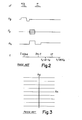
- Figure 1 shows a magnetic resonance scanner 10 having a large encircling magnet 12 for generating magnetic fields within a patient aperture 14. Shown in proximity to the magnet 12 is a patient couch 16 having a headrest 18. A patient is positioned on the couch 16 in a prone position and then moved into the patient aperture 14 for magnetic resonance scanning.
- a probe coil or resonator 20 is moved on rollers 22 so that the patient's head is positioned within the coil 20. Kith the probe coil 20 encircling the patient's head, the coil is energized with a high frequency signal which sets up a time varying magnetic field in the region of interest.
- the probe coil 20 also monitors signals from the patient as magnetic moments decay from an excited to steady state condition.
- Gradient coils 30 ( Figure lA) also encircle the patient to produce gradient fields G x , Gy, G z which in combination with the high strength field of the magnet 12 selectively focus on particular patient regions. Additional details regarding a magnetic resonance scanner configuration are disclosed in U.S. Patent No. 4,355,282 to Young et al which is incorporated herein by reference.
- Prior art magnetic resonance imaging sequences are based on two dimensional Fourier transform (2DFT) phase encoding techniques.
- 2DFT two dimensional Fourier transform
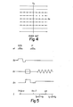
- An example sequence for planar excitation of a spin-echo ⁇ scan is shown in Figure 2.
- a phase encoding gradient, Gy is varied from one view to the next and N views of data are collected.
- a 2DFT reconstruction algorithm is then applied.
- the signal sensed by the probe coil 20 can be expressed as a function of time t (centered at an echo position) and the view number or the value of the phase encoding gradient Gy.
- the signal for the ideal planar case (no change in spin-density over the z-direction for a given point (x,y) in the plane) is proportional to and ⁇ is the gyromagnetic ratio in Hz/Gaus.
- f(x,y,t) is a product of the spin-density of the element of interest ⁇ (x,y) times a function f(t) which depends on the relaxation time parameters and the system parameters such as ⁇ and t re p.
- n the view number (centered about zero)
- ⁇ Gv the phase encoding increment from view to view. If this gradient is on for a time ty, one finds
- the sampling interval is 80 ⁇ s giving a Nyquist frequency of 6.25 kHz.
- the field cf view for body images is 45 cm, giving a value of 0.0654 G/cm for the read gradient G x .
- the values of the gradients are scaled by 1.5 for head images where the field of view is 30 cm ih each direction. In theory, the resolution attainable is roughly 1.2 mm for head images and 1.8 mm for body images.
- the aim of the present hybrid imaging method is to collect the data faster by taking fewer views and yet retain the same amount of information as in the standard 2DFT approach. This is accomplished by oscillating the phase encoding gradient after the initial phase encodement.
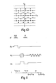
- An example hybrid sequence of the invention is shown in Figure 5.
- Figures 6 and 7 For a time savings of 2, the corresponding coverage of Fourier space before and after sampling is illustrated in Figures 6 and 7, respectively.
- Figure 7 one sees that, by oversampling each view by a factor of two, the same number of data points (in Fourier space) are covered as in Figure 4.
- oversampling the same number of data points are covered per reorganized view as in each of the views taken in a 2DFT scan. The difference is that the sampled points in every other view are shifted by one-half a sampling interval. Half as many views are required and yet Fourier space is effectively covered as in the 2DFT case. This allows the identical resolution calculated above to be obtained by practice of the invention.
- the hybrid sequence ( Figure 5) differs fundamentally from the standard sequence in that the increment of the phase encoding field Gy from view to view is larger by a factor of q, where q is a positive integer less than or equal to N in a-prior art 2DFT scan.
- q is a positive integer less than or equal to N in a-prior art 2DFT scan.
- the amplitude of the oscillating gradient should be such that the phase at one-quarter of a period is equal to what it would have been q/2 views away at that time in a 2DFT sequence.
- sinusoidal modulation of frequency ⁇ and amplitude Go for sinusoidal modulation of frequency ⁇ and amplitude Go,
- the frequency is such that one-half the period occurs in one sampling interval or
- the present technique is very susceptible to static field inhomogeneities. If the size of the object in the read direction is c x L, then the read gradient could be increased by a factor of I/c x to improve resolution. Then, for display purposes, the image can be reduced to its proper dimensions.
- Table 1 illustrates how to convert from the oversampled data to pseudo-2DFT sampled data for positive m.
- the pseudo prefix here means that further data manipulation may be required.
- the following relationships do not depend on the type of modulation of Gy(t), i.e., sinusoidal versus triangular, as long as data space is covered as in Figure 7.
- p 1 + q/2
- mod(a,b) where [ means integer part of. For a ⁇ 0 one must replace mod(a,b) with mod (a,b) + q.
- This table can be generalized for any frequency of oscillation. It is easier to put in practice when the frequency is an integer multiple of the ideal frequency,63 or when it is smaller than ⁇ by an integral factor.
- each new rebinning view has the same number of points.
- the frequency of oscillation is reduced (as in Figure 12) the rebinning procedure becomes more complicated in that each hybrid view has points associated with more normal 2DFT views.
- each sampled point is associated with a higher view in normal data until the peak is reached, then each point is associated with a lower view (by 1 unit) until a minimum is reached and the process is repeated until all data is sorted.
- the edges of data space can be filled in by taking extra views or by phase shifting again (as described below) to effectively recenter the shifted data. The latter approach only slightly degrades resolution, the former does not.
- the next step is to shift the even rows (odd n) to the right so that all the points for a given m (time point) lie in the same column. This is accomplished by implementing a data filtering operation.
- g(t) could be the signal for example.
- the hybrid technique consists of phase encoding the data with constant and oscillatory gradients.
- the data must be reorganized or rebinned so that a 2DFT type reconstruction is possible.
- the data Before the image can be reconstructed, the data must be filtered after the first Fourier transform.
- the gradient coil system has a low Q and a broad frequency response. This allows the shaping of the phase encoding gradient to be facilitated but makes it difficult to drive the system at 2 kHz with large amplitudes.
- Uniform coverage is obtained by breaking up the columns into two sets of uniformly spaced samples.
- the two data sets are fcrmed by first selecting all even sampled points and filling the void of the odd points with zeros and second, selecting the odd points and filling the void of even points with zeros.
- These two data sets are transformed separately. Take the signal for a column to be c(t) and for the column split into even and odd parts as ge(t) and g o (t) , respectively. Note that t is the phase variable. Once again, we take the central point tc be even.
- the discrete transform of each of these functions [g e (f) and g o (f) will have aliased contributions which, for ideal amplitude, will cancel when the transforms are added together.
- This technique can be extended to any number of non- uniformly spaced points.
- the effect of the oscillating amplitudes, filtering, and amplitude corrections is to take coherent noise and make it incoherent as well as causing the noise to be distributed throughout the image. This is advantageous especially when periodic motion of the object being imaged occurs. For example, eye motion causes noise to be distributed in the phase encoding direction throughout the vicinity of the eyes. This does not occur with the present hybrid method.
- the integrated phase encoding noise which only occurs in the region of the object being imaged, is more uniformly distributed throughout the field of view. This can improve the background noise in the image noticeably.
- noise can also occur in the form of uncorrected aliased images.
- the present implementation of the q equal to 2 hybrid technique results in a low read gradient of 0.02 G/cm to attain an ideal amplitude.
- This low gradient is sensitive to field inhomogeneities.
- the possible solutions to this sensitivity include: first, increasing the available voltage by adding gradient amplifiers in series to the present configuration; second, tuning the gradient coil circuit; or third, developing a low frequency hybrid technique.
- FIG. 13 Another use of the invention is for volume imaging. In this case, noise will be so low that any increase by a factor of 2 or 2 will not be of consequence. Being able to maintain resolution but decrease data collection times by factors of 2 and possibly much more will make volume imaging a viable technique.
- a sequence is shown in Figure 13. Here a selective 90° pulse along z and a selective 180° pulse along y are used to excite a rectangular strip along x. Filtering the signal will then allow various sizes of the strip to be isolated while a fregrency offset would allow the center of the volume of fnterest to be shifted. The oscillation of both z and y gradients allows information from as many as nine rows in k-space to be collected.
- Planar volume means that each data acquisition proceeds as in the two-dimensional example in that the oscillating gradients are applied parallel to only one of the phase encoding gradients. In this case, no new rebinning algorithms are required.
- the noise in the image in the hybrid method can be reduced by obtaining more uniform coverage of data space initially.
- FIG. 14 A portion of data space for q and m both equal to 4 is shown in Figure 14.
- the circles along line "c" represent normally sampled points properly rebinned.
- the circles and squares along row 130 have also been rebinned. Further rebinning is required as discussed below.
- projection reconstructio has no phase encoding gradient. Instead, data space is covered by varying the ratio of the G x and Gy read gradient components from scan to scan. This variation can be parameterized by the angle, ⁇ made with the k x axis. A partial normal coverage is illustrated in Figure 15 by the solid lines. A complete coverage asually has the radial lines uniformly spaced in ⁇ with ircrements ⁇ ⁇ . Once again by oscillating the gradients (this time both G x and Gy) and sampling faster, it is possible to acquire a complete coverage of data space q times faster. In this case, the time modulations are more complicated than before. The data must be similarly rebinned and filtered prior to reconstruction.
- the present invention is seen to be adaptable many variations, all aimed at recovering the equivalent of uniform or sufficient Fourier space (or k-space) data coverage at enhanced rates by use of a hybrid phase encoding procedure in order to maintain resolution. It is the intent the invention encompass all such variations, modifications and alterations falling within the spirit or scope of the appended claims.
Landscapes
- Physics & Mathematics (AREA)
- High Energy & Nuclear Physics (AREA)
- General Health & Medical Sciences (AREA)
- General Physics & Mathematics (AREA)
- Health & Medical Sciences (AREA)
- Condensed Matter Physics & Semiconductors (AREA)
- Signal Processing (AREA)
- Engineering & Computer Science (AREA)
- Radiology & Medical Imaging (AREA)
- Nuclear Medicine, Radiotherapy & Molecular Imaging (AREA)
- Life Sciences & Earth Sciences (AREA)
- Chemical & Material Sciences (AREA)
- Analytical Chemistry (AREA)
- Biochemistry (AREA)
- Immunology (AREA)
- Pathology (AREA)
- Magnetic Resonance Imaging Apparatus (AREA)
Applications Claiming Priority (2)
| Application Number | Priority Date | Filing Date | Title |
|---|---|---|---|
| US06/731,509 US4678996A (en) | 1985-05-07 | 1985-05-07 | Magnetic resonance imaging method |
| US731509 | 1985-05-07 |
Publications (2)
| Publication Number | Publication Date |
|---|---|
| EP0201277A2 true EP0201277A2 (fr) | 1986-11-12 |
| EP0201277A3 EP0201277A3 (fr) | 1987-10-28 |
Family
ID=24939821
Family Applications (1)
| Application Number | Title | Priority Date | Filing Date |
|---|---|---|---|
| EP86303283A Withdrawn EP0201277A3 (fr) | 1985-05-07 | 1986-04-30 | Appareil et procédé pour la production d'images par résonance magnétique |
Country Status (4)
| Country | Link |
|---|---|
| US (2) | US4678996A (fr) |
| EP (1) | EP0201277A3 (fr) |
| JP (1) | JPS61255647A (fr) |
| CA (1) | CA1251259A (fr) |
Cited By (2)
| Publication number | Priority date | Publication date | Assignee | Title |
|---|---|---|---|---|
| EP0240319A2 (fr) * | 1986-03-31 | 1987-10-07 | Kabushiki Kaisha Toshiba | Système pour la production d'image par résonance magnétique |
| GB2208718A (en) * | 1987-08-14 | 1989-04-12 | Nat Res Dev | Improvements in or relating to nmr imaging |
Families Citing this family (43)
| Publication number | Priority date | Publication date | Assignee | Title |
|---|---|---|---|---|
| NL8402959A (nl) * | 1984-09-28 | 1986-04-16 | Philips Nv | Snelle werkwijze en inrichting voor het bepalen van een kernmagnetisatieverdeling in een deel van een lichaam. |
| US4724386A (en) * | 1985-09-30 | 1988-02-09 | Picker International, Inc. | Centrally ordered phase encoding |
| US4841248A (en) * | 1985-08-14 | 1989-06-20 | Picker International, Inc. | Transverse field limited localized coil for magnetic resonance imaging |
| DE3604280A1 (de) * | 1986-02-12 | 1987-08-13 | Philips Patentverwaltung | Verfahren zur bestimmung der raeumlichen und der spektralen verteilung der kernmagnetisierung in einem untersuchungsbereich und anordnung zur durchfuehrung des verfahrens |
| IL82878A0 (en) * | 1986-06-18 | 1987-12-20 | Philips Nv | Method of and device for reconstructing a nuclear magnetization distribution from a partial magnetic resonance measurement |
| US4767991A (en) * | 1986-12-03 | 1988-08-30 | Advanced Nmr Systems, Inc. | Method of high speed imaging with improved spatial resolution using partial k-space acquisitions |
| JP2644744B2 (ja) * | 1987-02-04 | 1997-08-25 | 株式会社日立製作所 | Nmrスペクトロスコピックイメージング装置 |
| US4881033A (en) * | 1987-06-24 | 1989-11-14 | Picker International, Inc. | Noise-reduced synthetic T2 weighted images |
| JP2594953B2 (ja) * | 1987-07-08 | 1997-03-26 | 株式会社日立製作所 | 核磁気共鳴を用いた検査装置 |
| US4761613A (en) * | 1987-08-12 | 1988-08-02 | Picker International, Inc. | Monitored echo gating for the reduction of motion artifacts |
| DE3726932A1 (de) * | 1987-08-13 | 1989-02-23 | Spectrospin Ag | Verfahren zum kodieren von n parametern bei der mehrdimensionalen fourier-nmr-spektroskopie |
| US4973111A (en) * | 1988-09-14 | 1990-11-27 | Case Western Reserve University | Parametric image reconstruction using a high-resolution, high signal-to-noise technique |
| US4910460A (en) * | 1988-12-05 | 1990-03-20 | University Of Medicine & Dentistry Of New Jersey | Method and apparatus for mapping eddy currents in magnetic resonance imaging |
| GB2228090B (en) * | 1989-02-01 | 1993-09-22 | Gen Electric Co Plc | Magnetic resonance methods |
| GB8914467D0 (en) * | 1989-06-23 | 1989-08-09 | Nat Res Dev | Nuclear magnetic resonance imaging methods |
| US5233301A (en) * | 1989-07-28 | 1993-08-03 | Board Of Trustees Of The Leland Stanford Junior University | High resolution/reduced slice width magnetic resonance imaging and spectroscopy by signal combination and use of minimum phase excitation pulses |
| US5119027A (en) * | 1989-08-14 | 1992-06-02 | Ehrhardt James C | Nuclear magnetic resonance imaging method |
| US4982161A (en) * | 1989-08-24 | 1991-01-01 | North American Philips Corporation | Multimode magnetic resonance fast imaging method |
| EP0722093A1 (fr) * | 1989-12-01 | 1996-07-17 | Siemens Aktiengesellschaft | Procédé pour le fonctionnement d'un appareil de tomographie à spin nucléaire avec un circuit résonant pour la production de gradients de champs |
| JPH03173531A (ja) * | 1989-12-01 | 1991-07-26 | Hitachi Ltd | 磁気共鳴イメージング装置の渦電流補償方法及び渦電流補償装置 |
| US5239266A (en) * | 1990-08-03 | 1993-08-24 | The Regents Of The University Of California | MRI using variable imaging parameter(s) within a single image sequence |
| US5122747A (en) * | 1990-11-21 | 1992-06-16 | Mayo Foundation For Medical Education And Research | Spiral three-dimensional fourier transform NMR scan |
| US5151656A (en) * | 1990-12-11 | 1992-09-29 | General Electric Company | Correction of nmr data acquired by an echo-planar technique |
| US5243284A (en) * | 1991-07-24 | 1993-09-07 | Board Of Trustees Of The Leland Stanford Junior University | Method of magnetic resonance reconstruction imaging from projections using partial data collected in k-space |
| EP0533173B1 (fr) * | 1991-09-19 | 1996-11-20 | Kabushiki Kaisha Toshiba | Procédé et appareil pour la production d'images par résonance magnétique capable de compenser la pertubation du gradient de champ dué aux courants de Foucault |
| US5420803A (en) * | 1992-11-18 | 1995-05-30 | Technology Development Group, Inc. | Enhanced resolution wafer thickness measurement system |
| US5386632A (en) * | 1993-01-12 | 1995-02-07 | Pacific Handy Cutter, Inc. | Ergonomic utility knife/box cutter and method of making |
| WO1997004329A1 (fr) * | 1995-07-20 | 1997-02-06 | Philips Electronics N.V. | Procede et dispositif d'imagerie d'une partie incurvee du corps par resonance magnetique |
| US6043652A (en) * | 1997-04-17 | 2000-03-28 | Picker International, Inc. | Alternative reconstruction method for non-equidistant k-space data |
| US6144873A (en) * | 1998-04-17 | 2000-11-07 | Board Of Trustees Of The Leland Stanford Junior University | Method of efficient data encoding in dynamic magnetic resonance imaging |
| US6411089B1 (en) | 2000-11-22 | 2002-06-25 | Philips Medical Systems (Cleveland), Inc. | Two-dimensional phase-conjugate symmetry reconstruction for 3d spin-warp, echo-planar and echo-volume magnetic resonance imaging |
| US7450982B2 (en) * | 2003-03-14 | 2008-11-11 | Hitachi Medical Corporation | Magnetic resonance imaging system and method |
| US7786729B2 (en) | 2006-10-31 | 2010-08-31 | Regents Of The University Of Minnesota | Method for magnetic resonance imaging |
| CN101308202B (zh) * | 2007-05-17 | 2011-04-06 | 西门子公司 | 并行采集图像重建的方法和装置 |
| FR2923598B1 (fr) * | 2007-11-14 | 2012-01-20 | Univ Nancy 1 Henri Poincare | Procede de reconstruction d'un signal a partir de mesures experimentales perturbees et dispositif de mise en oeuvre |
| US20090182222A1 (en) * | 2008-01-10 | 2009-07-16 | Yoshio Machida | Magnetic resonance imaging appatatus and image reconstruction method |
| EP2177925A1 (fr) * | 2008-10-16 | 2010-04-21 | RWTH Aachen | Procédé de résonance magnétique utilisant un train d'impulsions avec modulation de phase et un angle d'inclinaison faible et constant |
| US9999778B2 (en) | 2009-08-11 | 2018-06-19 | Koninklijke Philips N.V. | Non-magnetic high voltage charging system for use in cardiac stimulation devices |
| JP4820441B2 (ja) * | 2009-09-30 | 2011-11-24 | ジーイー・メディカル・システムズ・グローバル・テクノロジー・カンパニー・エルエルシー | 磁気共鳴イメージング装置 |
| US8798340B2 (en) * | 2009-11-10 | 2014-08-05 | Regents Of The University Of Minnesota | Dipole matched filter for MRI |
| JP5926516B2 (ja) * | 2010-09-30 | 2016-05-25 | 株式会社東芝 | 磁気共鳴イメージング装置 |
| KR101568214B1 (ko) * | 2014-02-25 | 2015-11-11 | 고려대학교 산학협력단 | 자기 공명 영상장치 및 이를 이용한 자기 공명 영상방법 |
| US10945700B2 (en) * | 2015-03-02 | 2021-03-16 | B-K Medical Aps | Non-invasive estimation of intravascular pressure changes using vector velocity ultrasound (US) |
Citations (3)
| Publication number | Priority date | Publication date | Assignee | Title |
|---|---|---|---|---|
| FR2533031A1 (fr) * | 1982-09-10 | 1984-03-16 | Philips Nv | Procede et dispositif pour definir dans une partie d'un corps la densite de noyaux soumis a resonance magnetique |
| EP0177990A1 (fr) * | 1984-09-10 | 1986-04-16 | Koninklijke Philips Electronics N.V. | Procédé et appareil pour la détermination à grande vitesse de la distribution d'un spin nucléaire dans une partie d'un corps |
| EP0181015A1 (fr) * | 1984-09-28 | 1986-05-14 | Koninklijke Philips Electronics N.V. | Procédé et dispositif pour déterminer à grande vitesse la distribution de la magnétisation nucléaire dans une région d'un corps |
Family Cites Families (24)
| Publication number | Priority date | Publication date | Assignee | Title |
|---|---|---|---|---|
| US3873909A (en) * | 1967-08-21 | 1975-03-25 | Varian Associates | Gyromagnetic apparatus employing computer means for correcting its operating parameters |
| US3916385A (en) * | 1973-12-12 | 1975-10-28 | Honeywell Inf Systems | Ring checking hardware |
| CA1052861A (fr) * | 1975-03-18 | 1979-04-17 | Varian Associates | Zeugmatographie par resonance gyromagnetique a l'aide de la transformee de fourier |
| GB1596160A (en) * | 1976-12-15 | 1981-08-19 | Nat Res Dev | Nuclear magnetic resonance apparatus and methods |
| GB1584950A (en) * | 1978-05-25 | 1981-02-18 | Emi Ltd | Imaging systems |
| JPS5516229A (en) * | 1978-07-21 | 1980-02-04 | Hitachi Ltd | Fourier transformation type nuclear magnetic resonance device |
| US4340862A (en) * | 1978-12-13 | 1982-07-20 | Picker International Limited | Imaging systems |
| NL7904986A (nl) * | 1979-06-27 | 1980-12-30 | Philips Nv | Werkwijze en inrichting voor het bepalen van een kernspindichtheidsverdeling in een deel van een lichaam. |
| US4355282A (en) * | 1979-08-03 | 1982-10-19 | Picker International Limited | Nuclear magnetic resonance systems |
| US4384255A (en) * | 1979-08-10 | 1983-05-17 | Picker International Limited | Nuclear magnetic resonance systems |
| US4307343A (en) * | 1979-08-20 | 1981-12-22 | General Electric Company | Moving gradient zeugmatography |
| DE2945057C2 (de) * | 1979-11-08 | 1984-06-07 | Philips Patentverwaltung Gmbh, 2000 Hamburg | Verfahren zur Verminderung von Bildfehlern in mit Hilfe einer durchdringenden Strahlung hergestellten Schichtbildern eines dreidimensionalen Objektes |
| WO1981002788A1 (fr) * | 1980-03-14 | 1981-10-01 | Nat Res Dev | Procedes de production d'informations d'images a partir d'objets |
| JPS5838539A (ja) * | 1981-08-31 | 1983-03-07 | 株式会社東芝 | 診断用核磁気共鳴装置 |
| GB2107469B (en) * | 1981-09-21 | 1985-09-18 | Peter Mansfield | Nuclear magnetic resonance methods |
| US4506327A (en) * | 1981-11-23 | 1985-03-19 | General Electric Company | Limited-angle imaging using multiple energy scanning |
| US4607223A (en) * | 1982-08-13 | 1986-08-19 | National Research Development Corporation | Nuclear magnetic resonance imaging method |
| EP0105700B1 (fr) * | 1982-10-06 | 1989-01-04 | Peter Mansfield | Méthodes d'analyse utilisant la résonance magnétique nucléaire |
| US4516075A (en) * | 1983-01-04 | 1985-05-07 | Wisconsin Alumni Research Foundation | NMR scanner with motion zeugmatography |
| US4499493A (en) * | 1983-02-22 | 1985-02-12 | The Board Of Trustees Of The Leland Stanford Junior University | Multiple measurement noise reducing system using artifact edge identification and selective signal processing |
| US4639671A (en) * | 1983-05-31 | 1987-01-27 | General Electric Company | Simultaneous NMR imaging system |
| US4595879A (en) * | 1983-11-14 | 1986-06-17 | Technicare Corporation | Nuclear magnetic resonance flow imaging |
| US4591789A (en) * | 1983-12-23 | 1986-05-27 | General Electric Company | Method for correcting image distortion due to gradient nonuniformity |
| US4617624A (en) * | 1984-04-16 | 1986-10-14 | Goodman James B | Multiple configuration memory circuit |
-
1985
- 1985-05-07 US US06/731,509 patent/US4678996A/en not_active Expired - Fee Related
- 1985-08-09 US US06/764,439 patent/US4701706A/en not_active Expired - Lifetime
-
1986
- 1986-02-10 CA CA000501485A patent/CA1251259A/fr not_active Expired
- 1986-04-30 EP EP86303283A patent/EP0201277A3/fr not_active Withdrawn
- 1986-05-07 JP JP61104595A patent/JPS61255647A/ja active Pending
Patent Citations (3)
| Publication number | Priority date | Publication date | Assignee | Title |
|---|---|---|---|---|
| FR2533031A1 (fr) * | 1982-09-10 | 1984-03-16 | Philips Nv | Procede et dispositif pour definir dans une partie d'un corps la densite de noyaux soumis a resonance magnetique |
| EP0177990A1 (fr) * | 1984-09-10 | 1986-04-16 | Koninklijke Philips Electronics N.V. | Procédé et appareil pour la détermination à grande vitesse de la distribution d'un spin nucléaire dans une partie d'un corps |
| EP0181015A1 (fr) * | 1984-09-28 | 1986-05-14 | Koninklijke Philips Electronics N.V. | Procédé et dispositif pour déterminer à grande vitesse la distribution de la magnétisation nucléaire dans une région d'un corps |
Non-Patent Citations (3)
| Title |
|---|
| IEEE SPECTRUM, vol. 20, February 1983, pages 32-38, IEEE, New York, US; P.A. BOTTOMLEY: "Nuclear magnetic resonance: beyond physical imaging" * |
| MEDICAL PHYSICS, vol. 13, no. 2, March/April 1986, pages 248-253, Am. Assoc. Phys. Med., New York, US; J.J.M. CUPPEN et al.: "Magnetic resonance fast Fourier imaging" * |
| RADIOLOGY, vol. 158, 1986, pages 521-529, Easton, US; E.M. HAACKE et al.: "Reduction of MR imaging time by the hybrid fast-scan technique" * |
Cited By (4)
| Publication number | Priority date | Publication date | Assignee | Title |
|---|---|---|---|---|
| EP0240319A2 (fr) * | 1986-03-31 | 1987-10-07 | Kabushiki Kaisha Toshiba | Système pour la production d'image par résonance magnétique |
| EP0240319A3 (en) * | 1986-03-31 | 1989-08-30 | Kabushiki Kaisha Toshiba | Magnetic resonance imaging system |
| GB2208718A (en) * | 1987-08-14 | 1989-04-12 | Nat Res Dev | Improvements in or relating to nmr imaging |
| GB2208718B (en) * | 1987-08-14 | 1992-04-15 | Nat Res Dev | Improvements in or relating to nmr imaging |
Also Published As
| Publication number | Publication date |
|---|---|
| JPS61255647A (ja) | 1986-11-13 |
| EP0201277A3 (fr) | 1987-10-28 |
| US4701706A (en) | 1987-10-20 |
| US4678996A (en) | 1987-07-07 |
| CA1251259A (fr) | 1989-03-14 |
Similar Documents
| Publication | Publication Date | Title |
|---|---|---|
| EP0201277A2 (fr) | Appareil et procédé pour la production d'images par résonance magnétique | |
| US5879299A (en) | Method and system for multidimensional localization and for rapid magnetic resonance spectroscopic imaging | |
| US5402067A (en) | Apparatus and method for rare echo imaging using k-space spiral coverage | |
| EP0135847B1 (fr) | Procédé de formation d'images par résonance magnétique nucléaire utilisant des séquences d'impulsions combinant l'excitation sélective et la précession libre commandée | |
| US5657758A (en) | Method and system for multidimensional localization and for rapid magnetic resonance spectroscopic imaging | |
| EP0256779B1 (fr) | Dispositif pour l'imagerie rapide par résonance magnétique nucléaire | |
| US4734646A (en) | Method for obtaining T1-weighted and T2-weighted NMR images for a plurality of selected planes in the course of a single scan | |
| US4740748A (en) | Method of high-speed magnetic resonance imaging | |
| EP0329299B1 (fr) | Appareil et procédé pour la production d'images par résonance magnétique | |
| EP0144026B1 (fr) | Appareil et procéde pour la production d'images par résonance magnétique nucléaire avec balayage zoom décentré | |
| EP0413511A2 (fr) | Imagerie pour résonance magnétique nucléaire | |
| US5212448A (en) | Nmr pulse sequence with burst rf excitation pulses having separately controlled phase | |
| EP1636604B1 (fr) | Imagerie isotrope des vaisseaux avec suppression des graisses | |
| JP3850495B2 (ja) | Nmrデータから画像を生成する方法及び装置 | |
| JPH0568674A (ja) | 複素なnmr画像データのアレイにおける誤差を修正する方法 | |
| JP4546179B2 (ja) | スピンエコーシーケンスを用いた磁気共鳴断層撮影における周辺の妨害信号の回避方法および磁気共鳴断層撮影装置 | |
| JPH07171122A (ja) | Epi及びgrase mriにおける読み出し傾斜磁界極性の補正方法 | |
| US5602476A (en) | Ultra-fast MR imaging data acquisition scheme using mixed bandwidth data | |
| JPH05269112A (ja) | 流れ補償されたssfpパルスシーケンスを使用するnmrイメージング法 | |
| US4940941A (en) | Method of high-speed magnetic resonance imaging | |
| EP0372814B1 (fr) | Système pour l'imagerie par résonance magnétique | |
| US4818942A (en) | Method of high-speed magnetic resonance imaging employing continuous wave readout gradient | |
| US6424153B1 (en) | On-the-fly removal of data inconsistency with k-space oversampling and demodulation in MRI acquisitions | |
| US5309101A (en) | Magnetic resonance imaging in an inhomogeneous magnetic field | |
| US5581181A (en) | Grase MRI with read gradient polarity correction and T2 measurement |
Legal Events
| Date | Code | Title | Description |
|---|---|---|---|
| PUAI | Public reference made under article 153(3) epc to a published international application that has entered the european phase |
Free format text: ORIGINAL CODE: 0009012 |
|
| AK | Designated contracting states |
Kind code of ref document: A2 Designated state(s): DE FR GB NL |
|
| PUAL | Search report despatched |
Free format text: ORIGINAL CODE: 0009013 |
|
| AK | Designated contracting states |
Kind code of ref document: A3 Designated state(s): DE FR GB NL |
|
| STAA | Information on the status of an ep patent application or granted ep patent |
Free format text: STATUS: THE APPLICATION IS DEEMED TO BE WITHDRAWN |
|
| 18D | Application deemed to be withdrawn |
Effective date: 19880429 |
|
| RIN1 | Information on inventor provided before grant (corrected) |
Inventor name: BEARDEN, FRANCIS H Inventor name: HAACKE, E. MARK |