EP0200938B1 - Transfer medium feed mechanism for printers - Google Patents
Transfer medium feed mechanism for printers Download PDFInfo
- Publication number
- EP0200938B1 EP0200938B1 EP86104761A EP86104761A EP0200938B1 EP 0200938 B1 EP0200938 B1 EP 0200938B1 EP 86104761 A EP86104761 A EP 86104761A EP 86104761 A EP86104761 A EP 86104761A EP 0200938 B1 EP0200938 B1 EP 0200938B1
- Authority
- EP
- European Patent Office
- Prior art keywords
- transfer medium
- tension
- feed
- see
- friction
- Prior art date
- Legal status (The legal status is an assumption and is not a legal conclusion. Google has not performed a legal analysis and makes no representation as to the accuracy of the status listed.)
- Expired - Lifetime
Links
Images


Classifications
-
- B—PERFORMING OPERATIONS; TRANSPORTING
- B41—PRINTING; LINING MACHINES; TYPEWRITERS; STAMPS
- B41J—TYPEWRITERS; SELECTIVE PRINTING MECHANISMS, i.e. MECHANISMS PRINTING OTHERWISE THAN FROM A FORME; CORRECTION OF TYPOGRAPHICAL ERRORS
- B41J33/00—Apparatus or arrangements for feeding ink ribbons or like character-size impression-transfer material
- B41J33/14—Ribbon-feed devices or mechanisms
- B41J33/24—Ribbon-feed devices or mechanisms with drive applied directly to ribbon
- B41J33/26—Ribbon-feed devices or mechanisms with drive applied directly to ribbon by rollers engaging the ribbon
Definitions
- This invention relates to a transfer medium feed mechanism and, more particularly, to a feeding mechanism for a thermal printer in which there is conservation of a thermal transfer medium from which a marking material is transferred when it is softened by heat to a flowable state.
- the feeding of the ribbon in EP-A-102,474 is accomplished by having a pair of pinch rolls engage the ribbon after using the ribbon to print on the sheet of paper.
- the ribbon feeding mechanism of EP-A-102,474 also has drag brake means between the source of the ribbon and the printhead to create a tension on the ribbon at the print point.
- the present invention is an improvement of the thermal printer of EP-A-102,474. It has been found that the sliding force of the ribbon against the sheet of paper has a sufficient magnitude to pull the ribbon from the supply spool during printing in the thermal printer of EP-A-102,474. Thus, while the ribbon feed mechanism of EP-A-102,474 conserves ribbon, accurate metering of the ribbon relative to the paper is not always obtainable because of the inability of a brake/tensioning mechanism of the ribbon feed mechanism of EP-A-102,474 to restrain the ribbon with any repeatability and reliability.
- the ribbon feeding mechanism To obtain accurate metering of the ribbon relative to the sheet of paper, the ribbon feeding mechanism must pull the ribbon from its cartridge and meter it onto the sheet of paper at a consistent velocity irrespective of variations in the unwind tension and the frictional characteristics of the ribbon. This must occur without damaging the ribbon such as by scratching, wrinkling, or overstressing the ribbon, for example, prior to printing.
- the thermal printer of the EP-A-102,474 conserves ribbon, there is no recognition that consistent conservation of the ribbon can be obtained where the premetering tension, which is the tension on the ribbon prior to the metering roll and is the sum of the tension created by drag brake means and the unwind tension, is maintained substantially constant and the take-up tension is maintained substantially constant as the feed mechanism of the present invention can accomplish.
- the ratio of the take-up tension to the premetering tension at a selected value since the two tensions can be maintained substantially constant, slippage of the ribbon during feeding is avoided.
- the magnitude of the drag brake tension which constitutes part of the premetering tension in addition to the unwind tension, is the product of the coefficient of friction between the ribbon and the pad of the drag brake and the normal force of the ribbon on the pad.
- the coefficient of friction does not remain constant because each ribbon has variations from other ribbons to create slight differences in the coefficient of friction with the pad of the drag brake. Further changes in the coefficient of friction occur due to wear of the surfaces over which the ribbon passes and the build up of contaminants over such surfaces. Thus, these variations in the coefficient of friction do not enable a consistent velocity to be applied to the ribbon so that the most effective conservation of the ribbon is not obtained.
- the drag brake is opened when the drag brake tension increases beyond a predetermined tension so that there is no control of the premetering tension during this time. After a period of time, the drag brake again closes to again enable control of the premetering tension. Accordingly, an increase in the coefficient of friction causes more frequent opening of the drag brake to cause more frequent fluctuation in the premetering tension.
- the present invention solves the problem of the changes in the frictional characteristics of the ribbon causing variations in the premetering tension through utilizing an arrangement in which changes in the coefficient of friction between the ribbon and the material of the drag brake has no substantial effect on the premetering tension. This is accomplished through relieving the normal force of the ribbon on the pad of the drag brake as the coefficient of friction increases. Thus, there is not a linear increase in the premetering tension due to an increase in either the coefficient of friction or the normal force as occurs in the aforesaid EP-A-102,474.
- the present invention solves this problem through positioning feed means for the ribbon as close as possible to the printhead and prior to the printhead.
- the location of the feed means prior to the printhead eliminates the use of any type of pinch or nip rolls as is shown in EP-A-102,474 and on pages 204-207 of Volume 27, No. 1A (June 1984) issue of the IBM Technical Disclosure Bulletin.
- the present invention uses a single feed or metering roll, which engages the ribbon prior to the printhead, having a high coefficient of friction with the ribbon.
- the ribbon also has a relatively large wrap angle around the feed or metering roll. This high coefficient of friction and the large wrap angle insures that there is no slippage of the ribbon relative to the feed or metering roll.
- the ribbon feed roll of the present invention also is subjected to build up of ink on its outer surface so as to have its coefficient of friction with the ribbon changed over a period of time.
- the continued use of the contaminated feed roll would result in an inconsistent feed velocity because slippage of the ribbon relative to the metering roll could occur due to the reduced coefficient of friction.
- This problem is solved through mounting the feed roll on a cartridge having the ribbon supply. Accordingly, the feed roll is replaced each time that the cartridge is replaced so that the need for any cleaning of the feed roll is avoided.
- the use of the feed roll is in accordance with the amount of ribbon employed, and the quantity of ribbon in the cartridge is selected so that there is not any significant change in the coefficient of friction between the ribbon and the feed roll before the ribbon is exhausted.
- the thermal printer of the present invention has an arrangement to reduce the normal force of the ribbon on the drag brake pad as the ribbon passes through the drag brake when the coefficient of friction increases. This arrangement also is employed to guide the ribbon to cause the ribbon to wrap around more than 90° of the feed roll.
- the thermal printer of the present invention is an improvement of the thermal printer of the aforesaid EP-A-102,474 in that the ribbon may be fed at various selected velocities through its own power source.
- the carrier which carries the printhead is driven from a second power source at various selected velocities. While the aforesaid EP-A-102,474 discussed the use of two separate power sources for feeding the ribbon and driving the carrier, there is no recognition in EP-A-102,474 that more than two conservation modes (draft and quality) could be utilized although there is a description of a very large range of ratios and velocities.
- the thermal printer of the present invention may operate in three different conservation modes (draft, quality, and enhanced) with the underfeed ratios (the ratio of the print speed to the ribbon feed rate) being 5:1; 2:1, and 1.2:1, respectively.
- the thermal printer of the present invention With the carrier having a very high speed such as 160 characters per second with ten pitch characters, the thermal printer of the present invention is in the draft mode wherein the conservation of the ribbon enables the ribbon cost when printing in the draft mode to be in the same range as that of a fabric ribbon used with a speed, dot matrix printer.
- the carrier of the thermal printer of the present invention at a speed of 100 characters per second with ten pitch characters, the quality mode is obtained to produce letter quality print.
- the enhanced mode occurs to produce the best print.
- the thermal printer of the present invention is capable of very high speed printing when operating in the draft mode, it still does not exceed the maximum current for a selected ribbon length in a selected period of time that can be produced from the electrodes of the thermal printhead. Because of the higher speed of the printhead and the lower speed of the ribbon, there is a longer dwell at each character space by the ribbon; this allows utilization of a lower current for a selected ribbon length in a selected period of time even though the total current may be relatively large.
- the drive rollers are rotatably supported by the cartridge which is located far away from the printhead. Such rollers are not equiped with a friction means.
- the present invention does provide a single feed roll which has a friction means and other functions described before. Besides, the location of the feed means close to the printhead and prior to the printhead minimizes the stretching or relaxing of the ribbon. And the shape of the cartridge housing with its extension can support this type of feed roll.
- the feed mechanism of the present invention feeds ribbon at a substantially constant velocity, irrespective of variations in the ribbon, and avoids significant changes in the premetering tension due to changes in the coefficient of friction between the ribbon and the drag brake. This is accomplished through decreasing the normal force of the ribbon on the drag brake pad as the coefficient of friction between the ribbon and the drag brake increases and conversely.
- the use of the feed roll is controlled so that its use is not so long as to require the feed roll to be cleaned but is automatically replaced when the ribbon in the cartridge is fully used. This avoids the danger of the feed roll having the ribbon slip relative thereto because of a substantial change in the coefficient of friction due to build up of contaminants on the feed roll so as to affects the feeding of the ribbon.
- the thermal printer of the present invention is capable of having substantially constant tensions applied to portions of the ribbon on opposite sides of the feed roll . This avoids any slippage of the ribbon on the feed roll.
- the positioning of the single feed roll prior to the printhead avoids the problem of damaging the ribbon while still obtaining the desired feed rate through having a desired coefficient of friction between the ribbon and the feed roll and a substantial wrap around of the ribbon on the feed roll.
- the peel angle of the ribbon should be decreased.
- the present invention accomplishes this through disposing control means beyond the printhead and before the take-up spool to control the peel angle between the sheet of paper and the tension producing means.
- a satisfactory peel angle is within the range of 1° to 10° with the preferred angle being 7.9°.
- An object of this invention is to provide a mechanism for feeding a transfer medium of a thermal printer at a substantially constant selected velocity past a thermal printhead.
- Another object of this invention is to provide a thermal printer having at least three printing modes for conservation of a transfer medium of a thermal printer.
- a further object of this invention is to provide a transfer medium cartridge for a thermal printer in which a feed roll for feeding the transfer medium is supported by the cartridge.
- Still another object of this invention is to provide a thermal printer in which substantially constant tensions are applied to the ribbon on opposite sides of the feed roll irrespective of the coefficient of friction of the transfer medium.
- a still further object of this invention is to provide a feed mechanism for feeding a transfer medium of a thermal printer at different velocities for different velocities of a thermal printhead.
- the thermal printer 10 includes an elongated, cylindrical platen 11 adapted to support a receiving or recording medium 12 such as a sheet of paper, for example, for receiving printing marks to be recorded thereon.
- a receiving or recording medium 12 such as a sheet of paper, for example, for receiving printing marks to be recorded thereon.
- the thermal printer 10 has a carrier 14 slidably mounted on rails 15 for movement parallel to a longitudinal axis 16 of the platen 11.
- the carrier 14 includes a flat plate 17 (see Fig. 3) having a pair of bearing supports 18 integral therewith and extending downwardly therefrom to slide along one of the rails 15 (see Fig. 1).
- the flat plate 17 (see Fig. 4) of the carrier 14 has a retainer 18' extending downwardly therefrom to slide along the other of the rails 15 (see Fig. 1).
- the carrier 14 is driven from a suitable drive system 19 (shown illustratively in Fig. 1) through a timing belt 20, which is attached to the carrier 14, connecting the drive system 19 to the carrier 14.
- a printhead 21 is mounted on a holder 22, which is pivotally mounted on a pivot pin 23 supported on the plate 17 of the carrier 14 and extending upwardly therefrom. Movement of the printhead 21 from a retracted position to an operative position at a print line 24 is produced by energizing a solenoid 25 (see Fig. 17), which is supported on the bottom of the plate 17, in a manner similar to that more particularly shown and described in the aforesaid EP-A-102,474.
- the energization of the solenoid 25 causes extension of a plunger of the solenoid 25 so that a pin 25A on the end of the plunger engages a lower arm 25B of a bracket 25C, which is pivotally mounted on the pivot pin 23, to pivot the bracket 25C clockwise about the pivot pin 23.
- This causes the printhead holder 22 to be pivoted clockwise with the bracket 25C due to a pin 25D on a portion of the bottom of the printhead holder 22 beneath the printhead 21 extending through an opening 25E in the plate 17 of the carrier 14 and being held against an upper arm 25F of the bracket 25C by a spring 25G, which extends between the upper arm 25F and the printhead holder 22.
- the printhead 21 has a plurality of electrodes 27 (see Fig. 5) arranged in a single line array.
- the transfer medium 28 (see Fig. 1) may be any suitable material for transferring printing marks to the medium 12 in accordance with the heat supplied from the particular energized electrodes 27 (see Fig. 5) of the printhead 21 such as the inked ribbon shown and described in the aforesaid EP-A-102,474.
- the transfer medium 28 (see Fig. 1) is supported in a cartridge 30, which is removably supported on pads 31 located on the plate 17 of the carrier 14.
- the cartridge 30 includes a housing formed of an upper portion or cover 32 connected to a lower portion or base 33.
- the housing base 33 includes a substantially planar floor 34 having a side wall 35 extending upwardly therefrom.
- An annular bearing portion 36 extends upwardly from the floor 34 of the housing 33 and has a core 36', which has the transfer medium 28 wrapped thereon, of a supply spool 37 rotatably supported thereby.
- the transfer medium 28 on the core 36' of the supply spool 37 exists from the housing base 33 through a first opening 38 in the side wall 35 into an extension 40 of the housing base 33 from which the transfer medium 28 exits through a first opening 41.
- the transfer medium 28 returns to the interior of the housing base 33 through a second opening 42 in the side wall 35 to provide a continuous span or length of the transfer medium 28 exterior of the cartridge 30.
- the second opening 42 does not extend throughout the height of the side wall 35 but only in the upper portion so that the transfer medium 28 is returned to the cartridge 30 for being wound around a take-up spool 43 in a different plane than the supply spool 37.
- the transfer medium 28 is changed from the plane of the supply spool 37 in the extension 40 of the housing base 33 of the cartridge 30.
- the take-up spool 43 includes a plate 44, which has holes 45 therein to lighten the weight to reduce the inertia, having an outer cylindrical portion 46 around which the transfer medium 28 is wrapped as the take-up spool 43 is rotated.
- the interior of the outer cylindrical portion 46 is hollow so that a hub 47 (see Fig. 6) is formed within the outer cylindrical portion 46.
- Ribs 48 extend from the hub 47 to the inner surface of the outer cylindrical portion 46.
- the interior of the hub 47 is hollow and has five teeth 49 thereon for meshing with five teeth 50 (see Fig. 7) on a driver 51.
- the driver 51 is attached to the upper end of a shaft 52, which is rotatably supported in a housing 53 fixed to the bottom of the plate 17 (see Fig. 1) of the carrier 14, for rotation therewith.
- a portion of the housing 53 extends through a circular opening 53' (see Fig. 3) in the plate 17 of the carrier 14. Because of the shaft 52 (see Fig. 7) having the driver 51 fixed thereto, the engagement of the bottom of the driver 51 with an upper surface 54 of the housing 53 holds the shaft 52 within the housing 53 while allowing rotation therein.
- a pawl 55 is attached to the shaft 52 for rotation therewith and has ends 55' cooperating with ratchet teeth 56 on an inner surface of a gear 57 to form a one-way clutch to enable rotation of the shaft 52 without rotation of the gear 57.
- the pawl 55 (see Fig. 7) rests on a head 58' on the end of the shaft 52.
- the take-up spool 43 (see Fig. 2) is supported on the driver 51 (see Fig. 7) so that it is rotated whenever the driver 51 rotates through the teeth 50 on the driver 51 meshing with the teeth 49 (see Fig. 6) on the hub 47 of the take-up spool 43.
- the driver 51 (see Fig. 7) is driven from a take-up motor 59, which is supported on a plate 59' (see Fig. 4) extending downwardly from the bottom of the plate 17 of the carrier 14, through a worm gear 60 (see Fig. 7) meshing with the gear 57.
- the take-up spool 43 (see Fig. 2) is supported on the driver 51 (see Fig. 7) for rotation therewith.
- the housing cover 32 (see Fig. 2) has pins 62 extending downwardly from its periphery for disposition within holes 63 in cylindrical portions 64 on the outer surface of the side wall 35 of the housing base 33 to connect the cover 32 and the base 33 to each other.
- An extension 65 on the cover 32 has similar pins 66 for disposition within holes 67 in upstanding cylindrical portions 68 in the extension 40.
- the transfer medium 28 passes around a roller 69 upon entering the extension 40 after exiting through the opening 38 and then in engagement with some of the cylindrical portions 68 within the extension 40 until the transfer medium 28 exits from the extension 40 of the cartridge 30 through the opening 41.
- the drag brake 70 includes a back-up pin 71, which is supported on the plate 17 of the carrier 14 and extends upwardly through a cut out portion 72 (see Fig. 17) in a plate or arm 73 of the drag brake 70.
- the plate 73 is pivotally mounted on the carrier 14 by a pivot pin 74 supported in an opening 74' (see Fig. 3) in the flat plate 17 of the carrier 14.
- the drag brake 70 (see Fig. 8) includes a pad 75, which is preferably formed of felt, supported in a holder 76.
- the holder 76 is disposed on an upstanding finger 77 of the plate 73 and has a portion 78 on the opposite side of the finger 77 from the pad 75.
- the holder 76 has a spherical portion 79 (see Fig. 9) engaging a socket 80 in the finger 77 to gimbally mount the holder 76 thereon so that the pad 75 engages the entire depth of the transfer medium 28 (see Fig. 17) as it passes between the back-up pin 71 and the pad 75.
- the portion 78 has a projection 80' (see Fig. 9) engaging the finger 77 on the side opposite from the socket 80 to provide stability.
- the transfer medium 28 passes around an idler 81, which is supported on the plate 73 in a position to guide the transfer medium 28 from the drag brake 70 to a feed or metering roll 82.
- the feed roll 82 is rotatably supported by the cartridge 30.
- the feed roll 82 includes a core 83, which is formed by injection molding of a suitable hard, dimensionally stable plastic such as glass-filled polyester, for example, having an upper bearing surface 84 rotatably supported in an opening 84' in the extension 65 of the housing cover 32 of the cartridge 30 and its lower surface 85 rotatably supported on the upper surface of the extension 40 of the housing base 33 of the cartridge 30.
- the core 83 has an outer surface 86 of a material having a relatively high coefficient of friction (e.g., greater than 0.7 and preferably 1.2) with the material of the transfer medium 28 (see Fig. 1) and preferably being elastomeric. It also is desirable for the material of the outer surface 86 (see Fig. 12) of the feed roll 82 to have some softness to aid in tracking the transfer medium 28 (see Fig. 1). Any differential loads across the height of the feed roll 82 (see Fig. 12) can be compensated to a degree by compression of the material of the outer surface 86 of the feed roll 82 during feeding of the transfer medium 28 (see Fig. 1). Suitable examples of the material of the outer surface 86 (see Fig. 12) of the feed roll 82 are urethane rubber, polyvinyl chloride, and microcellular urethane foam with the microcellular urethane foam being preferred.
- a relatively high coefficient of friction e.g., greater than 0.7 and preferably 1.2
- the outer surface 86 of the feed roll 82 By making the outer surface 86 of the feed roll 82 as thin as possible, a high torsional rigidity is obtained. This relative thinness of the outer surface 86 is obtained by injection molding the outer surface 86 on the core 83.
- the preferred thickness of the outer surface 86 of the feed roll 82 is 0.5 mm or less.
- the core 83 of the feed roll 82 has teeth 87 extending downwardly therefrom through an opening 87' in the extension 40 of the housing base 33 of the cartridge 30 for cooperating with teeth on a driver 88, which is attached to the upper end of a shaft 88A rotatably supported in a bushing 88B (see Fig.A3) on the carrier 14.
- the bottom end of the shaft 88A (see Fig. 12) has a gear forming part of gearing 89 (illustratively shown) driven from a motor 90 (illustratively shown), which is supported from the bottom of the plate 17 (see Fig. 1) of the carrier 14.
- the feed roll 82 (see Fig. 12) is supported on the cartridge 30 (see Fig. 2) so that it is discarded when the cartridge 30 no longer has any of the usable transfer medium 28 therein. This insures that the feed roll 82 does not have any significant reduction in its desired coefficient of friction during use.
- the transfer medium 28 passes the printhead 21 where the transfer medium 28 is heated by the electrodes 27 (see Fig. 5) of the printhead 21 to produce the desired marks on the medium 12 (see Fig. 1).
- the transfer medium 28 then passes around an idler 91 which is positioned to maintain a relatively low peel angle of the transfer medium 28 with respect to the medium 12. This insures that there is more time for contact with the medium 12 by the transfer medium 28 since the contact time increases as the peel angle decreases.
- the idler 91 is rotatably supported on a post 92 of a plate 93, which is mounted on the carrier 14 by a downwardly extending post 94 (see Fig. 10).
- the post 94 is rotatably supported on the plate 17 (see Fig. 3) of the carrier 14 after passing through a bushing 94' on the plate 17 of the carrier 14.
- a second post 95 extends upwardly from the plate 93 and has an idler 96 (see Fig. 1) rotatably supported thereby.
- the transfer medium 28 passes around the idler 96.
- the spacing of the idler 96 from the idler 91 insures that the transfer medium 28 will not tend to walk up or down the idlers 91 and 96 as could occur if they were positioned too close together. This also avoids any misalignment problems between the posts 92 and 95 as could occur if they were too close together.
- the transfer medium 28 After passing around the idler 96, the transfer medium 28 passes around an idler 97 on a tension arm 98, which is pivotally mounted on the carrier 14 by a pivot pin 99 extending through a bushing 99' (see Fig. 3) on the plate 17 of the carrier 14.
- a spring 100 (see Fig. 17), which has one end attached to the tension arm 98 and its other end connected to the bottom of the plate 17 of the carrier 14, continuously urges the tension arm 98 counterclockwise (as viewed in Fig. 17) about the pivot pin 99 to maintain a desired tension on the transfer medium 28.
- the transfer medium 28 After passing around the idler 97, the transfer medium 28 is guided by a roller 101 (see Fig. 1) on a post 102, which has a hole 103 therein to receive one of the pins 62 (see Fig. 2) on the housing cover 32, on the housing base 33. Then, the transfer medium 28 enters the cartridge 30 through the second opening 42 in the side wall 35 on the housing base 33. The transfer medium 28 is then wrapped around the outer cylindrical portion 46 of the take-up spool 43.
- the position of the tension arm 98 is sensed by an optical sensor 104 (see Fig. 14), which is mounted on the bottom of the plate 17 (see Fig. 1) of the carrier 14 through having a screw 104A (see Fig. 14) extend through an opening 104B in the optical sensor 104 and a threaded opening 104C (see Fig. 3) in the plate 17.
- the optical sensor 104 also has a foot 104D extending through an opening 104E (see Fig. 3) in the plate 17 to aid in retaining the optical sensor 104 (see Fig. 14) in position on the plate 17 (see Fig. 3).
- the optical sensor 104 see Fig. 14
- the flag 105 (see Fig. 14) is rotatably supported in a housing 108 of the optical sensor 104 for rotation about the center of a circular portion 109 (see Fig. 15) of the flag 105.
- the circular portion 109 has a pie-shaped opening 110 therein for cooperation with similar openings in the upper and lower portions of the housing 108 (see Fig. 14) of the optical sensor 104.
- the housing 108 has an LED in its upper portion and a photosensor in its lower portion so that the amount of light from the LED to the photosensor depends on the position of the pie-shaped opening 110 (see Fig. 15) in the circular portion 109 of the flag 105 relative to the similar pie-shaped openings, which are aligned with each other, beneath the LED and above the photosensor.
- a spring 111 (see Fig. 14), which has one end connected to a projection 111A on the housing 108 and its other end disposed in a hole 111B (see Fig. 15) in the flag 105, continuously urges the flag 105 about the center of the circular portion 109 so that the cam surface 106 of the flag 105 is held against the pin 107 (see Fig. 13) on the tension arm 98.
- the flag 105 (see Fig. 14) always follows the motion of the pin 107 (see Fig. 13) of the tension arm 98.
- the optical sensor 104 senses this change in light and activates the take-up motor 59 (see Fig. 7).
- the optical sensor 104 (see Fig. 14) is an analog sensor in that it causes advancement of only a very small amount of the transfer medium 28 (see Fig. 1) onto the take-up spool 43 (see Fig. 2) by the take-up motor 59 (see Fig. 7) in accordance with small light variations that is senses because the optical sensor 104 (see Fig. 14) responds to slight changes in the amount of light passing through the pie-shaped opening 110 (see Fig. 15) in the circular portion 109 of the flag 105.
- One suitable example of the optical sensor 104 is shown and described on pages 6156 and 6157 of Volume 27, No. 10B (March 1985) issue of the IBM Technical Disclosure Bulletin.
- the cartridge 30 (see Fig. 1) has its bottom supported on the three pads 31 on the flat plate 17 of the carrier 14.
- the cartridge 30 is positioned at its desired location on the carrier 14 through having a pair of grooves 117 and 118 in the side wall 35 receive upstanding guides 119 and 120 on the carrier 14 as the cartridge 30 is moved towards the flat plate 17 of the carrier 14.
- the lever 121 (see Fig. 11) includes a pair of upstanding arcuate segments 122 and 123 extending into arcuate openings 124 (see Fig. 3) and 125, respectively, in the flat plate 17 of the carrier 14.
- the arcuate segments 122 (see Fig. 11) and 123 of the lever 121 extend into arcuate openings 126 (see Fig. 2) and 127, respectively, in the floor 34 of the housing base 33 of the cartridge 30 when the cartridge 30 is positioned on the carrier 14 (see Fig. 1).
- the floor 34 (see Fig. 16) of the housing base 33 has a portion 128 at one end of the arcuate opening 126 and a portion 129 at one end of the arcuate opening 127.
- the portions 128 and 129 are formed to extend upwardly at an angle to the floor 34 of the housing base 33 and support the core 36' (see Fig. 2) of the supply spool 37 on their inner ends.
- the portion 129 (see Fig. 16) has a downwardly extending portion 130 at its inner end for engagement by a cam surface 131 (see Fig. 11) on the arcuate segment 123 of the lever 121 to enable the arcuate segment 123 to move the portion 129 (see Fig. 16) into the plane of the floor 34 when the lever 121 (see Fig. 11) is rotated counterclockwise (as viewed in Fig. 1).
- the arcuate segment 122 (see Fig. 11) of the lever 121 has a cam surface 132 to simultaneously move the portion 128 (see Fig.
- the supply spool 37 is prevented from accidental rotation. This insures that the transfer medium 28 is not accidentally withdrawn from the cartridge 30 before it is to be used while handling during loading.
- the lever 121 (see Fig. 11) has a finger 136 integral therewith carrying a roller 137 on its end for disposition within a slot 138 (see Fig. 17) in a bellcrank 139, which is rotatably mounted on a pin 140 carried by the flat plate 17 of the carrier 14.
- the roller 137 extends through an arcuate groove 141, which has the same center as the center of the lever 121, in the flat plate 17 of the carrier 14 for disposition within the slot 138 in the bellcrank 139.
- the clockwise rotation of the plate 73 causes a tab 145 On the plate 73 to engage a pin 146 on a portion of the bottom of the printhead holder 22 beneath the printhead 21 to rotate the printhead holder 22 counterclockwise about the pin 23. This moves the printhead 21 including the electrodes 27 (see Fig. 5) away from the transfer medium 28 (see Fig. 17).
- the bellcrank 139 has a pin 147 on a second finger 148 and disposed in a slot 149 in a toggle 150.
- the toggle 150 also is connected to the post 92 so that counterclockwise rotation of the bellcrank 139 about the pin 140 moves the pin 147 from the upper portion of the slot 149 in the toggle 150 to rotate the plate 93 clockwise (as viewed in Fig. 17) about the axis of the post 94 (see Fig. 10). This eliminates the tension on the transfer medium 28 (see Fig. 17) between the idlers 91 and 96.
- the clockwise (as viewed in Fig. 17) rotation of the lever 121 also causes the tension arm 98 to be rotated clockwise about the axis of the pivot pin 99 against the force of the spring 100.
- the cartridge 30 After the tension on the transfer medium 28 is removed through clockwise (as viewed in Fig. 1) rotation of the lever 121, the cartridge 30 is removed from its support on the flat plate 17 of the carrier 14. Then, another of the cartridges 30 is positioned so that the grooves 117 and 118 in the side wall 35 of the cartridge 30 receive the upstanding guides 119 and 120, respectively, on the carrier 14 as the cartridge 30 is moved downwardly to position the cartridge 30 on the pads 31 after which the lever 121 is rotated counterclockwise (as viewed in Fig. 1) to return the drag brake 70 to its operative position, the printhead 21 to its operative position, the idlers 91 and 96 to their tension producing positions, and the tension arm 98 to its tension producing position.
- T1 take-up tension T2 is the premetering tension
- e is a constant defining the natural logarithm
- ⁇ is the coefficient of friction between the transfer medium 28 and the feed roll 82
- a is the wrap around angle in radians of the transfer medium 28 around the feed roll 82.
- the take-up tension, T1 is created by the spring 100 acting on the tension arm 98. Through the use of the optical sensor 104 (see Fig. 14), the take-up tension T1 is maintained substantially constant.
- the premetering tension T2 is the sum of the tension created by the drag brake 70 (see Fig. 1) and the unwind tension at the supply spool 37 (see Fig. 2). Since the unwind tension at the supply spool 37 is of lesser magnitude, it is only necessary to maintain the tension created by the drag brake 70 substantially constant irrespective of the coefficient of friction between the drag brake 70 and the transfer medium 28.
- the solid line in Fig. 18 shows the relationship of the ratio of the tension created by the drag brake 70 to the maximum normal force relative to the sum of the coefficients of friction between the transfer medium 28 and the drag brake pad 75 and between the transfer medium 28 and the back-up pin 71.
- a change of 300% in the coefficient of friction (0.3 to 0.9, for example) only results in a maximum change in tension of 50% since the maximum normal force is constant.
- the ratio of T1/T2 is maintained substantially constant and relatively low. Therefore, there will not be slippage of the transfer medium 28 relative to the feed roll 82 whereby a substantially constant velocity of the feed of the transfer medium 28 is obtained with this being the tangential velocity of the outer surface 86 (see Fig. 12) of the feed roll 82 as driven by the motor 90.
- transfer medium 28 (see Fig. 2) has been shown as being supplied from the core 36' of the supply spool 37 of the cartridge 30, it should be understood that the feed mechanism of the present invention may be readily utilized with any source of the transfer medium 28. Thus, any other type of cartridge could be utilized or the transfer medium 28 could be supplied from other than a cartridge, if desired.
- the ratio of T1/T2 or T2/T1 be capable of being at least 3 to accommodate dynamic loading. This is accomplished by selecting the material of the coefficient of friction of the outer surface 86 (see Fig. 22) of the feed roll 82 so that it will have a coefficient of friction of at least 0.7.
- transfer medium 28 has been shown and described as being a heat transfer medium, it should be understood that the cartridge 30 could be utilized with the transfer medium 28 being other than a heat transfer medium. Thus, any other suitable type of transfer medium could be utilized with the cartridge 30.
- cartridge 30 has been shown and described as being used with the thermal printer 10, it should be understood that the cartridge 30 could be employed with any printer in which it is desired to have the feed roll 82 supported on the cartridge 30 to control the length of time that the feed roll 82 is used before being replaced.
- An advantage of this invention is that it conserves the use of ribbon at different rates of conservation depending upon the desired print quality. Another advantage of this invention is that it avoids deterioration of the feed or metering roll for feeding the transfer medium past the printhead. A further advantage of this invention is that there is automatic replacement of the feed or metering roll when a predetermined amount of ribbon has been fed by the feed of metering roll. Still another advantage of this invention is that it overcomes the tendency for friction of the ribbon at the recording medium to negate underfeed. A still further advantage of this invention is that it has a low peel angle when used with a thermal transfer medium to increase the contact time of the thermal transfer medium with the recording or receiving medium such as a sheet of paper. Yet another advantage of this invention is that changes in the coefficient of friction between the transfer medium and the drag brake do no affect the premetering tension on the transfer medium.
Description
- This invention relates to a transfer medium feed mechanism and, more particularly, to a feeding mechanism for a thermal printer in which there is conservation of a thermal transfer medium from which a marking material is transferred when it is softened by heat to a flowable state.
- It has previously been suggested in EP-A-102,474, to have conservation of a thermal transfer medium such as an inked ribbon, for example, by underfeeding the ribbon relative to movement of a thermal printhead of a thermal printer. This results in the ribbon sliding relative to both the printhead and a recording or receiving medium such as a sheet of paper, for example, during formation of the print.
- In the preferred embodiment of EP-A-102,474, feeding of both a carrier which carries the printhead and the ribbon occur from a single power source through using gears and selectively changing the gear ratios to feed the ribbon at different velocities relative to the velocity of the printhead. EP-A-102,474 also suggests that two separate power sources could be utilized for driving the carrier which carries the printhead and the ribbon.
- The feeding of the ribbon in EP-A-102,474 is accomplished by having a pair of pinch rolls engage the ribbon after using the ribbon to print on the sheet of paper. The ribbon feeding mechanism of EP-A-102,474 also has drag brake means between the source of the ribbon and the printhead to create a tension on the ribbon at the print point.
- The present invention is an improvement of the thermal printer of EP-A-102,474. It has been found that the sliding force of the ribbon against the sheet of paper has a sufficient magnitude to pull the ribbon from the supply spool during printing in the thermal printer of EP-A-102,474. Thus, while the ribbon feed mechanism of EP-A-102,474 conserves ribbon, accurate metering of the ribbon relative to the paper is not always obtainable because of the inability of a brake/tensioning mechanism of the ribbon feed mechanism of EP-A-102,474 to restrain the ribbon with any repeatability and reliability.
- To obtain accurate metering of the ribbon relative to the sheet of paper, the ribbon feeding mechanism must pull the ribbon from its cartridge and meter it onto the sheet of paper at a consistent velocity irrespective of variations in the unwind tension and the frictional characteristics of the ribbon. This must occur without damaging the ribbon such as by scratching, wrinkling, or overstressing the ribbon, for example, prior to printing.
- While the thermal printer of the EP-A-102,474 conserves ribbon, there is no recognition that consistent conservation of the ribbon can be obtained where the premetering tension, which is the tension on the ribbon prior to the metering roll and is the sum of the tension created by drag brake means and the unwind tension, is maintained substantially constant and the take-up tension is maintained substantially constant as the feed mechanism of the present invention can accomplish. By maintaining the ratio of the take-up tension to the premetering tension at a selected value since the two tensions can be maintained substantially constant, slippage of the ribbon during feeding is avoided.
- In EP-A-102,474, the magnitude of the drag brake tension, which constitutes part of the premetering tension in addition to the unwind tension, is the product of the coefficient of friction between the ribbon and the pad of the drag brake and the normal force of the ribbon on the pad. The coefficient of friction does not remain constant because each ribbon has variations from other ribbons to create slight differences in the coefficient of friction with the pad of the drag brake. Further changes in the coefficient of friction occur due to wear of the surfaces over which the ribbon passes and the build up of contaminants over such surfaces. Thus, these variations in the coefficient of friction do not enable a consistent velocity to be applied to the ribbon so that the most effective conservation of the ribbon is not obtained.
- It should be understood that the drag brake is opened when the drag brake tension increases beyond a predetermined tension so that there is no control of the premetering tension during this time. After a period of time, the drag brake again closes to again enable control of the premetering tension. Accordingly, an increase in the coefficient of friction causes more frequent opening of the drag brake to cause more frequent fluctuation in the premetering tension.
- There also are changes in the coefficient of friction due to ribbon feed leaders, which have a very low coefficient of friction, and the ribbon ends, which may be abrasive so as to have a relatively high coefficient of friction. Each of these has an effect on the velocity of the ribbon when these portions of the ribbon pass the drag brake.
- The present invention solves the problem of the changes in the frictional characteristics of the ribbon causing variations in the premetering tension through utilizing an arrangement in which changes in the coefficient of friction between the ribbon and the material of the drag brake has no substantial effect on the premetering tension. This is accomplished through relieving the normal force of the ribbon on the pad of the drag brake as the coefficient of friction increases. Thus, there is not a linear increase in the premetering tension due to an increase in either the coefficient of friction or the normal force as occurs in the aforesaid EP-A-102,474.
- It also has been discovered that another effect on the feed velocity of the ribbon occurs during printing because of changes in friction between the thermal printhead and the ribbon and between the sheet of paper and the ribbon. During printing, heat from the electrodes of the printhead increases the friction between the printhead and the ribbon and decreases the friction between the sheet of paper and the ribbon. As these changes in friction occur, the ribbon has to stretch or relax depending on the net force change. The minimization of stretching or relaxing of the ribbon occurs when the stiffness of the ribbon is at a maximum in the area just prior to the printhead.
- The present invention solves this problem through positioning feed means for the ribbon as close as possible to the printhead and prior to the printhead. The location of the feed means prior to the printhead eliminates the use of any type of pinch or nip rolls as is shown in EP-A-102,474 and on pages 204-207 of
Volume 27, No. 1A (June 1984) issue of the IBM Technical Disclosure Bulletin. - While the aforesaid IBM Technical Disclosure Bulletin shows nip rolls engaging the ribbon prior to the printhead, these could damage the ribbon prior to printing so that the nip rolls of the aforesaid IBM Technical Disclosure Bulletin are undesirable for feeding the ribbon prior to the printhead. There also is no recognition in the aforesaid IBM technical Disclosure Bulletin of disposing the nip rolls as close as possible to the printhead to maintain the portion of the ribbon between the nip rolls and the printhead substantially stiff to minimize stretching or relaxing of the ribbon during printing and minimize any appreciable effect on the velocity of the ribbon.
- While the aforesaid IBM Technical Disclosure Bulletin discusses a constant tension on the supply spool, this is based on an assumption that the coefficient of friction between the ribbon and the braking surface pad remains constant. However, the coefficient of friction of different ribbons relative to the pad is not normally the same, and there is wear of the pad and/or build up of ink on the pad so as to change the coefficient of friction between the ribbon and the pad. As previously discussed, each of these variations has a significant effect on the coefficient of friction so as to change the premetering tension whereby it would not be constant.
- To avoid damage to the ribbon prior to printing, the present invention uses a single feed or metering roll, which engages the ribbon prior to the printhead, having a high coefficient of friction with the ribbon. The ribbon also has a relatively large wrap angle around the feed or metering roll. This high coefficient of friction and the large wrap angle insures that there is no slippage of the ribbon relative to the feed or metering roll.
- The ribbon feed roll of the present invention also is subjected to build up of ink on its outer surface so as to have its coefficient of friction with the ribbon changed over a period of time. The continued use of the contaminated feed roll would result in an inconsistent feed velocity because slippage of the ribbon relative to the metering roll could occur due to the reduced coefficient of friction.
- This problem is solved through mounting the feed roll on a cartridge having the ribbon supply. Accordingly, the feed roll is replaced each time that the cartridge is replaced so that the need for any cleaning of the feed roll is avoided. The use of the feed roll is in accordance with the amount of ribbon employed, and the quantity of ribbon in the cartridge is selected so that there is not any significant change in the coefficient of friction between the ribbon and the feed roll before the ribbon is exhausted.
- As previously mentioned, the thermal printer of the present invention has an arrangement to reduce the normal force of the ribbon on the drag brake pad as the ribbon passes through the drag brake when the coefficient of friction increases. This arrangement also is employed to guide the ribbon to cause the ribbon to wrap around more than 90° of the feed roll.
- The thermal printer of the present invention is an improvement of the thermal printer of the aforesaid EP-A-102,474 in that the ribbon may be fed at various selected velocities through its own power source. The carrier which carries the printhead is driven from a second power source at various selected velocities. While the aforesaid EP-A-102,474 discussed the use of two separate power sources for feeding the ribbon and driving the carrier, there is no recognition in EP-A-102,474 that more than two conservation modes (draft and quality) could be utilized although there is a description of a very large range of ratios and velocities.
- The thermal printer of the present invention may operate in three different conservation modes (draft, quality, and enhanced) with the underfeed ratios (the ratio of the print speed to the ribbon feed rate) being 5:1; 2:1, and 1.2:1, respectively. With the carrier having a very high speed such as 160 characters per second with ten pitch characters, the thermal printer of the present invention is in the draft mode wherein the conservation of the ribbon enables the ribbon cost when printing in the draft mode to be in the same range as that of a fabric ribbon used with a speed, dot matrix printer. When operating the carrier of the thermal printer of the present invention at a speed of 100 characters per second with ten pitch characters, the quality mode is obtained to produce letter quality print. At a lower speed such as 80 characters per second with ten pitch characters, the enhanced mode occurs to produce the best print.
- While the thermal printer of the present invention is capable of very high speed printing when operating in the draft mode, it still does not exceed the maximum current for a selected ribbon length in a selected period of time that can be produced from the electrodes of the thermal printhead. Because of the higher speed of the printhead and the lower speed of the ribbon, there is a longer dwell at each character space by the ribbon; this allows utilization of a lower current for a selected ribbon length in a selected period of time even though the total current may be relatively large.
- In the document EP-A-082-957, the drive rollers are rotatably supported by the cartridge which is located far away from the printhead. Such rollers are not equiped with a friction means.
- The present invention does provide a single feed roll which has a friction means and other functions described before. Besides, the location of the feed means close to the printhead and prior to the printhead minimizes the stretching or relaxing of the ribbon. And the shape of the cartridge housing with its extension can support this type of feed roll.
- The feed mechanism of the present invention feeds ribbon at a substantially constant velocity, irrespective of variations in the ribbon, and avoids significant changes in the premetering tension due to changes in the coefficient of friction between the ribbon and the drag brake. This is accomplished through decreasing the normal force of the ribbon on the drag brake pad as the coefficient of friction between the ribbon and the drag brake increases and conversely.
- By mounting the feed roll on the cartridge, the use of the feed roll is controlled so that its use is not so long as to require the feed roll to be cleaned but is automatically replaced when the ribbon in the cartridge is fully used. This avoids the danger of the feed roll having the ribbon slip relative thereto because of a substantial change in the coefficient of friction due to build up of contaminants on the feed roll so as to affects the feeding of the ribbon.
- Through maintaining a substantially constant premetering tension, the thermal printer of the present invention is capable of having substantially constant tensions applied to portions of the ribbon on opposite sides of the feed roll . This avoids any slippage of the ribbon on the feed roll.
- The positioning of the single feed roll prior to the printhead avoids the problem of damaging the ribbon while still obtaining the desired feed rate through having a desired coefficient of friction between the ribbon and the feed roll and a substantial wrap around of the ribbon on the feed roll.
- The changes in frictions between the thermal printhead and the ribbon and between the sheet of paper and the ribbon during printing, due to heating of the ribbon do not have a significant effect on the ribbon because the ribbon is substantially stiff between the printhead and the feed roll through positioning the feed roll as close as possible to the printhead.
- As the speed of the printhead increases, the contact time of the ribbon with the sheet of paper decreases. To insure that there is sufficient contact time of the ribbon with the sheet of paper to have satisfactory print, particularly in the draft mode, the peel angle of the ribbon should be decreased. The present invention accomplishes this through disposing control means beyond the printhead and before the take-up spool to control the peel angle between the sheet of paper and the tension producing means. A satisfactory peel angle is within the range of 1° to 10° with the preferred angle being 7.9°.
- An object of this invention is to provide a mechanism for feeding a transfer medium of a thermal printer at a substantially constant selected velocity past a thermal printhead.
- Another object of this invention is to provide a thermal printer having at least three printing modes for conservation of a transfer medium of a thermal printer.
- A further object of this invention is to provide a transfer medium cartridge for a thermal printer in which a feed roll for feeding the transfer medium is supported by the cartridge.
- Still another object of this invention is to provide a thermal printer in which substantially constant tensions are applied to the ribbon on opposite sides of the feed roll irrespective of the coefficient of friction of the transfer medium.
- A still further object of this invention is to provide a feed mechanism for feeding a transfer medium of a thermal printer at different velocities for different velocities of a thermal printhead.
- The foregoing and other objects, features, and advantages of the invention will be apparent from the following more particular description of the preferred embodiment of the invention as illustrated in the accompanying drawings.
- In the drawings :
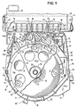
- Fig. 1 is a top plan view of a portion of a thermal printer having a feed mechanism for feeding a thermal transfer medium.
- Fig. 2 is an exploded perspective view of a thermal transfer medium supply cartridge employed with the thermal printer of Fig. 1.
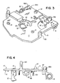
- Fig. 3 is a perspective view of a carrier of the thermal printer of Fig. 1 without any parts mounted on the carrier.
- Fig. 4 is a side elevational view of the carrier of Fig. 3.
- Fig. 5 is a perspective view of a portion of the thermal printhead of Fig. 1 and showing its electrodes.
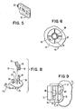
- Fig. 6 is a fragmentary bottom plan view of a central portion of a take-up spool of the cartridge of Fig. 2.
- Fig. 7 is an exploded perspective view of the drive arrangement for the take-up spool of the cartridge of Fig. 2.
- Fig. 8 is an exploded perspective view of portions of a drag brake of the thermal printer of Fig. 1.
- Fig. 9 is an enlarged top plan view of a portion of the drag brake of Fig. 8.
- Fig. 10 is a perspective view of a portion of the thermal printer of Fig. 1.
- Fig. 11 is a perspective view of a lever for locking and unlocking the cartridge to the carrier of the thermal printer of Fig. 1 and an arm for moving a tension arm of the thermal printer of Fig. 1 to an inactive position when the cartridge is removed from the carrier.
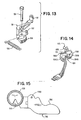
- Fig. 12 is a fragmentary sectional view of the thermal printer of Fig. 1 and showing a feed roll supported by the cartridge and illustrating its drive.
- Fig. 13 is an exploded perspective view of a tension arm of the thermal printer of Fig. 1.
- Fig. 14 is a perspective view of an optical sensor for sensing the position of the tension arm.
- Fig. 15 is a top plan view of a rotatable flag of the optical sensor of Fig. 14.
- Fig. 16 is an enlarged fragmentary top plan view of a housing base of the supply cartridge of Fig. 2.
- Fig. 17 is an enlarged fragmentary top plan view of a portion of the carrier of the thermal printer of Fig. 1 without the cartridge but showing a portion of the thermal transfer medium and its feed roll.
- Fig. 18 is a graph showing the relation of the normal force between a thermal transfer medium and a drag brake having a pad of felt and a back-up metal pin and the coefficient of friction between the thermal transfer medium and the drag brake and the relation of a premetering tension force on the thermal transfer medium and the coefficient of friction between the thermal transfer medium and the drag brake.
- Referring to the drawings and particularly Fig. 1, there is shown a
thermal printer 10. Thethermal printer 10 includes an elongated,cylindrical platen 11 adapted to support a receiving orrecording medium 12 such as a sheet of paper, for example, for receiving printing marks to be recorded thereon. - The
thermal printer 10 has acarrier 14 slidably mounted onrails 15 for movement parallel to alongitudinal axis 16 of theplaten 11. Thecarrier 14 includes a flat plate 17 (see Fig. 3) having a pair of bearing supports 18 integral therewith and extending downwardly therefrom to slide along one of the rails 15 (see Fig. 1). The flat plate 17 (see Fig. 4) of thecarrier 14 has a retainer 18' extending downwardly therefrom to slide along the other of the rails 15 (see Fig. 1). Thecarrier 14 is driven from a suitable drive system 19 (shown illustratively in Fig. 1) through atiming belt 20, which is attached to thecarrier 14, connecting thedrive system 19 to thecarrier 14. - A
printhead 21 is mounted on aholder 22, which is pivotally mounted on apivot pin 23 supported on theplate 17 of thecarrier 14 and extending upwardly therefrom. Movement of theprinthead 21 from a retracted position to an operative position at aprint line 24 is produced by energizing a solenoid 25 (see Fig. 17), which is supported on the bottom of theplate 17, in a manner similar to that more particularly shown and described in the aforesaid EP-A-102,474. - The energization of the
solenoid 25 causes extension of a plunger of thesolenoid 25 so that apin 25A on the end of the plunger engages a lower arm 25B of abracket 25C, which is pivotally mounted on thepivot pin 23, to pivot thebracket 25C clockwise about thepivot pin 23. This causes theprinthead holder 22 to be pivoted clockwise with thebracket 25C due to a pin 25D on a portion of the bottom of theprinthead holder 22 beneath theprinthead 21 extending through anopening 25E in theplate 17 of thecarrier 14 and being held against anupper arm 25F of thebracket 25C by aspring 25G, which extends between theupper arm 25F and theprinthead holder 22. - When the
printhead 21 engages the platen 11 (see Fig. 1), movement of theprinthead holder 22 is stopped, but there is a slight further movement of thebracket 25C (see Fig. 17) due to the plunger of thesolenoid 25 having its motion stopped by adisc 25H, which is attached to the plunger of thesolenoid 25, abutting the rear end of thesolenoid 25. This results in thespring 25G loading theprinthead 21 against the medium 12 (see Fig. 1). When the solenoid 25 (see Fig. 17) is deenergized, areturn spring 26 returns theprinthead 21 to its retracted position. - The
printhead 21 has a plurality of electrodes 27 (see Fig. 5) arranged in a single line array. Theelectrodes 27, which are held in the loaded position by thespring 25G (see Fig. 17), are selectively energized in response to signals and generate heat in portions of a transfer medium 28 (see Fig. 1) to cause marking material of thetransfer medium 28 to be transferred to the medium 12 when the marking material is softened to a flowable state by heat from the electrodes 27 (see Fig. 5) of theprinthead 21. The transfer medium 28 (see Fig. 1) may be any suitable material for transferring printing marks to the medium 12 in accordance with the heat supplied from the particular energized electrodes 27 (see Fig. 5) of theprinthead 21 such as the inked ribbon shown and described in the aforesaid EP-A-102,474. - The transfer medium 28 (see Fig. 1) is supported in a
cartridge 30, which is removably supported onpads 31 located on theplate 17 of thecarrier 14. As shown in Fig. 2, thecartridge 30 includes a housing formed of an upper portion or cover 32 connected to a lower portion orbase 33. - The
housing base 33 includes a substantiallyplanar floor 34 having aside wall 35 extending upwardly therefrom. Anannular bearing portion 36 extends upwardly from thefloor 34 of thehousing 33 and has a core 36', which has thetransfer medium 28 wrapped thereon, of asupply spool 37 rotatably supported thereby. Thetransfer medium 28 on the core 36' of thesupply spool 37 exists from thehousing base 33 through afirst opening 38 in theside wall 35 into anextension 40 of thehousing base 33 from which thetransfer medium 28 exits through afirst opening 41. - The
transfer medium 28 returns to the interior of thehousing base 33 through asecond opening 42 in theside wall 35 to provide a continuous span or length of the transfer medium 28 exterior of thecartridge 30. Thesecond opening 42 does not extend throughout the height of theside wall 35 but only in the upper portion so that thetransfer medium 28 is returned to thecartridge 30 for being wound around a take-upspool 43 in a different plane than thesupply spool 37. Thetransfer medium 28 is changed from the plane of thesupply spool 37 in theextension 40 of thehousing base 33 of thecartridge 30. - The take-up
spool 43 includes aplate 44, which hasholes 45 therein to lighten the weight to reduce the inertia, having an outercylindrical portion 46 around which thetransfer medium 28 is wrapped as the take-upspool 43 is rotated. The interior of the outercylindrical portion 46 is hollow so that a hub 47 (see Fig. 6) is formed within the outercylindrical portion 46.Ribs 48 extend from thehub 47 to the inner surface of the outercylindrical portion 46. - The interior of the
hub 47 is hollow and has fiveteeth 49 thereon for meshing with five teeth 50 (see Fig. 7) on adriver 51. Thedriver 51 is attached to the upper end of ashaft 52, which is rotatably supported in ahousing 53 fixed to the bottom of the plate 17 (see Fig. 1) of thecarrier 14, for rotation therewith. A portion of the housing 53 (see Fig.A7) extends through a circular opening 53' (see Fig. 3) in theplate 17 of thecarrier 14. Because of the shaft 52 (see Fig. 7) having thedriver 51 fixed thereto, the engagement of the bottom of thedriver 51 with anupper surface 54 of thehousing 53 holds theshaft 52 within thehousing 53 while allowing rotation therein. - A
pawl 55 is attached to theshaft 52 for rotation therewith and has ends 55' cooperating withratchet teeth 56 on an inner surface of agear 57 to form a one-way clutch to enable rotation of theshaft 52 without rotation of thegear 57. This occurs when a knob 58 (see Fig. 2) on the outercylindrical portion 46 is turned when thecartridge 30 is initially installed on the carrier 14 (See Fig. 1) to take up any slack in thetransfer medium 28 between the supply spool 37 (see Fig. 2) and the take-upspool 43. The pawl 55 (see Fig. 7) rests on a head 58' on the end of theshaft 52. - The take-up spool 43 (see Fig. 2) is supported on the driver 51 (see Fig. 7) so that it is rotated whenever the
driver 51 rotates through theteeth 50 on thedriver 51 meshing with the teeth 49 (see Fig. 6) on thehub 47 of the take-upspool 43. The driver 51 (see Fig. 7) is driven from a take-upmotor 59, which is supported on a plate 59' (see Fig. 4) extending downwardly from the bottom of theplate 17 of thecarrier 14, through a worm gear 60 (see Fig. 7) meshing with thegear 57. Thus, when the cartridge 30 (see Fig. 1) is mounted on thecarrier 14, the take-up spool 43 (see Fig. 2) is supported on the driver 51 (see Fig. 7) for rotation therewith. - The housing cover 32 (see Fig. 2) has
pins 62 extending downwardly from its periphery for disposition withinholes 63 incylindrical portions 64 on the outer surface of theside wall 35 of thehousing base 33 to connect thecover 32 and the base 33 to each other. Anextension 65 on thecover 32 hassimilar pins 66 for disposition withinholes 67 in upstandingcylindrical portions 68 in theextension 40. As shown in Fig. 1, the transfer medium 28 passes around aroller 69 upon entering theextension 40 after exiting through theopening 38 and then in engagement with some of thecylindrical portions 68 within theextension 40 until thetransfer medium 28 exits from theextension 40 of thecartridge 30 through theopening 41. - After leaving the
cartridge 30, the transfer medium 28 passes through adrag brake 70 on thecarrier 14. Thedrag brake 70 includes a back-uppin 71, which is supported on theplate 17 of thecarrier 14 and extends upwardly through a cut out portion 72 (see Fig. 17) in a plate orarm 73 of thedrag brake 70. Theplate 73 is pivotally mounted on thecarrier 14 by apivot pin 74 supported in an opening 74' (see Fig. 3) in theflat plate 17 of thecarrier 14. - The drag brake 70 (see Fig. 8) includes a
pad 75, which is preferably formed of felt, supported in aholder 76. Theholder 76 is disposed on anupstanding finger 77 of theplate 73 and has aportion 78 on the opposite side of thefinger 77 from thepad 75. Theholder 76 has a spherical portion 79 (see Fig. 9) engaging asocket 80 in thefinger 77 to gimbally mount theholder 76 thereon so that thepad 75 engages the entire depth of the transfer medium 28 (see Fig. 17) as it passes between the back-uppin 71 and thepad 75. Theportion 78 has a projection 80' (see Fig. 9) engaging thefinger 77 on the side opposite from thesocket 80 to provide stability. - After the transfer medium 28 (see Fig. 17) passes through the
drag brake 70, the transfer medium 28 passes around an idler 81, which is supported on theplate 73 in a position to guide the transfer medium 28 from thedrag brake 70 to a feed ormetering roll 82. Thefeed roll 82 is rotatably supported by thecartridge 30. As shown in Fig. 12, thefeed roll 82 includes a core 83, which is formed by injection molding of a suitable hard, dimensionally stable plastic such as glass-filled polyester, for example, having anupper bearing surface 84 rotatably supported in an opening 84' in theextension 65 of thehousing cover 32 of thecartridge 30 and itslower surface 85 rotatably supported on the upper surface of theextension 40 of thehousing base 33 of thecartridge 30. - The
core 83 has anouter surface 86 of a material having a relatively high coefficient of friction (e.g., greater than 0.7 and preferably 1.2) with the material of the transfer medium 28 (see Fig. 1) and preferably being elastomeric. It also is desirable for the material of the outer surface 86 (see Fig. 12) of thefeed roll 82 to have some softness to aid in tracking the transfer medium 28 (see Fig. 1). Any differential loads across the height of the feed roll 82 (see Fig. 12) can be compensated to a degree by compression of the material of theouter surface 86 of thefeed roll 82 during feeding of the transfer medium 28 (see Fig. 1). Suitable examples of the material of the outer surface 86 (see Fig. 12) of thefeed roll 82 are urethane rubber, polyvinyl chloride, and microcellular urethane foam with the microcellular urethane foam being preferred. - By making the
outer surface 86 of thefeed roll 82 as thin as possible, a high torsional rigidity is obtained. This relative thinness of theouter surface 86 is obtained by injection molding theouter surface 86 on thecore 83. The preferred thickness of theouter surface 86 of thefeed roll 82 is 0.5 mm or less. - The
core 83 of thefeed roll 82 hasteeth 87 extending downwardly therefrom through anopening 87' in theextension 40 of thehousing base 33 of thecartridge 30 for cooperating with teeth on adriver 88, which is attached to the upper end of a shaft 88A rotatably supported in a bushing 88B (see Fig.A3) on thecarrier 14. The bottom end of the shaft 88A (see Fig. 12) has a gear forming part of gearing 89 (illustratively shown) driven from a motor 90 (illustratively shown), which is supported from the bottom of the plate 17 (see Fig. 1) of thecarrier 14. - Thus, the feed roll 82 (see Fig. 12) is supported on the cartridge 30 (see Fig. 2) so that it is discarded when the
cartridge 30 no longer has any of the usable transfer medium 28 therein. This insures that thefeed roll 82 does not have any significant reduction in its desired coefficient of friction during use. - After the transfer medium 28 (see Fig. 1), which has a wrap around angle of greater than 90° around the
feed roll 82, passes around thefeed roll 82, the transfer medium 28 passes theprinthead 21 where thetransfer medium 28 is heated by the electrodes 27 (see Fig. 5) of theprinthead 21 to produce the desired marks on the medium 12 (see Fig. 1). Thetransfer medium 28 then passes around an idler 91 which is positioned to maintain a relatively low peel angle of thetransfer medium 28 with respect to the medium 12. This insures that there is more time for contact with the medium 12 by thetransfer medium 28 since the contact time increases as the peel angle decreases. - The idler 91 is rotatably supported on a
post 92 of aplate 93, which is mounted on thecarrier 14 by a downwardly extending post 94 (see Fig. 10). Thepost 94 is rotatably supported on the plate 17 (see Fig. 3) of thecarrier 14 after passing through a bushing 94' on theplate 17 of thecarrier 14. - A second post 95 (see Fig. 10) extends upwardly from the
plate 93 and has an idler 96 (see Fig. 1) rotatably supported thereby. The transfer medium 28 passes around theidler 96. The spacing of the idler 96 from the idler 91 insures that thetransfer medium 28 will not tend to walk up or down theidlers posts - After passing around the idler 96, the transfer medium 28 passes around an idler 97 on a
tension arm 98, which is pivotally mounted on thecarrier 14 by apivot pin 99 extending through a bushing 99' (see Fig. 3) on theplate 17 of thecarrier 14. A spring 100 (see Fig. 17), which has one end attached to thetension arm 98 and its other end connected to the bottom of theplate 17 of thecarrier 14, continuously urges thetension arm 98 counterclockwise (as viewed in Fig. 17) about thepivot pin 99 to maintain a desired tension on thetransfer medium 28. - After passing around the idler 97, the
transfer medium 28 is guided by a roller 101 (see Fig. 1) on apost 102, which has ahole 103 therein to receive one of the pins 62 (see Fig. 2) on thehousing cover 32, on thehousing base 33. Then, thetransfer medium 28 enters thecartridge 30 through thesecond opening 42 in theside wall 35 on thehousing base 33. Thetransfer medium 28 is then wrapped around the outercylindrical portion 46 of the take-upspool 43. - The position of the tension arm 98 (see Fig. 1) is sensed by an optical sensor 104 (see Fig. 14), which is mounted on the bottom of the plate 17 (see Fig. 1) of the
carrier 14 through having ascrew 104A (see Fig. 14) extend through anopening 104B in theoptical sensor 104 and a threadedopening 104C (see Fig. 3) in theplate 17. The optical sensor 104 (see Fig. 14) also has a foot 104D extending through an opening 104E (see Fig. 3) in theplate 17 to aid in retaining the optical sensor 104 (see Fig. 14) in position on the plate 17 (see Fig. 3). The optical sensor 104 (see Fig. 14) includes aflag 105 having acam surface 106 engaged by a pin 107 (see Fig. 13) on thetension arm 98 so that the flag 105 (see Fig. 14) follows the movement of the tension arm 98 (see Fig. 13). - The flag 105 (see Fig. 14) is rotatably supported in a
housing 108 of theoptical sensor 104 for rotation about the center of a circular portion 109 (see Fig. 15) of theflag 105. Thecircular portion 109 has a pie-shapedopening 110 therein for cooperation with similar openings in the upper and lower portions of the housing 108 (see Fig. 14) of theoptical sensor 104. Thehousing 108 has an LED in its upper portion and a photosensor in its lower portion so that the amount of light from the LED to the photosensor depends on the position of the pie-shaped opening 110 (see Fig. 15) in thecircular portion 109 of theflag 105 relative to the similar pie-shaped openings, which are aligned with each other, beneath the LED and above the photosensor. A spring 111 (see Fig. 14), which has one end connected to aprojection 111A on thehousing 108 and its other end disposed in ahole 111B (see Fig. 15) in theflag 105, continuously urges theflag 105 about the center of thecircular portion 109 so that thecam surface 106 of theflag 105 is held against the pin 107 (see Fig. 13) on thetension arm 98. Thus, the flag 105 (see Fig. 14) always follows the motion of the pin 107 (see Fig. 13) of thetension arm 98. As the light passing through the pie-shaped opening 110 (see Fig. 15) varies because of the position of the tension arm 98 (see Fig. 13) shifting, the optical sensor 104 (see Fig. 14) senses this change in light and activates the take-up motor 59 (see Fig. 7). - The optical sensor 104 (see Fig. 14) is an analog sensor in that it causes advancement of only a very small amount of the transfer medium 28 (see Fig. 1) onto the take-up spool 43 (see Fig. 2) by the take-up motor 59 (see Fig. 7) in accordance with small light variations that is senses because the optical sensor 104 (see Fig. 14) responds to slight changes in the amount of light passing through the pie-shaped opening 110 (see Fig. 15) in the
circular portion 109 of theflag 105. One suitable example of the optical sensor 104 (see Fig. 14) is shown and described on pages 6156 and 6157 ofVolume 27, No. 10B (March 1985) issue of the IBM Technical Disclosure Bulletin. - The cartridge 30 (see Fig. 1) has its bottom supported on the three
pads 31 on theflat plate 17 of thecarrier 14. Thecartridge 30 is positioned at its desired location on thecarrier 14 through having a pair ofgrooves side wall 35 receiveupstanding guides carrier 14 as thecartridge 30 is moved towards theflat plate 17 of thecarrier 14. - When it is desired to remove the
cartridge 30 from its support on the threepads 31 on theflat plate 17 of thecarrier 14, it is necessary to remove the tension on thetransfer medium 28. This is accomplished through rotating alever 121 clockwise (as viewed in Fig. 1) about the center of the supply spool 37 (see Fig. 2) and the center of the take-upspool 43, which are axially aligned with the center of theannular bearing portion 36 of thehousing base 33 of thecartridge 30. The lever 121 (see Fig. 11) has a circular opening 121' to receive a portion of the housing 53 (see Fig. 7). - The lever 121 (see Fig. 11) includes a pair of upstanding
arcuate segments flat plate 17 of thecarrier 14. The arcuate segments 122 (see Fig. 11) and 123 of thelever 121 extend into arcuate openings 126 (see Fig. 2) and 127, respectively, in thefloor 34 of thehousing base 33 of thecartridge 30 when thecartridge 30 is positioned on the carrier 14 (see Fig. 1). The floor 34 (see Fig. 16) of thehousing base 33 has aportion 128 at one end of thearcuate opening 126 and aportion 129 at one end of thearcuate opening 127. Theportions floor 34 of thehousing base 33 and support the core 36' (see Fig. 2) of thesupply spool 37 on their inner ends. - The portion 129 (see Fig. 16) has a downwardly extending
portion 130 at its inner end for engagement by a cam surface 131 (see Fig. 11) on thearcuate segment 123 of thelever 121 to enable thearcuate segment 123 to move the portion 129 (see Fig. 16) into the plane of thefloor 34 when the lever 121 (see Fig. 11) is rotated counterclockwise (as viewed in Fig. 1). The arcuate segment 122 (see Fig. 11) of thelever 121 has acam surface 132 to simultaneously move the portion 128 (see Fig. 16) into the plane of thefloor 34 by engaging a downwardly extending portion 132A at the inner end of theportion 128 in the same manner as the cam surface 131 (see Fig. 11) on thearcuate segment 123 moves the portion 129 (see Fig. 16) into the plane of thefloor 34 of thehousing base 33. This not only locks thecartridge 30 to the carrier 14 (see Fig. 1) through the arcuate segments 122 (see Fig. 11) and 123 overlapping the portions 128 (see Fig. 16) and 129, respectively, and engaging raisedportions floor 34 but it also enables withdrawal of atooth 133 on theportion 128 and atooth 134 on theportion 129 from teath 135 (see Fig. 2), which are on both sides of the core 36' of thesupply spool 37, on the bottom side of the core 36'. - When the
teeth teeth 135 on the bottom side of the core 36' of thesupply spool 37, thesupply spool 37 is prevented from accidental rotation. This insures that thetransfer medium 28 is not accidentally withdrawn from thecartridge 30 before it is to be used while handling during loading. - The lever 121 (see Fig. 11) has a
finger 136 integral therewith carrying aroller 137 on its end for disposition within a slot 138 (see Fig. 17) in abellcrank 139, which is rotatably mounted on apin 140 carried by theflat plate 17 of thecarrier 14. Theroller 137 extends through anarcuate groove 141, which has the same center as the center of thelever 121, in theflat plate 17 of thecarrier 14 for disposition within theslot 138 in thebellcrank 139. - When the
lever 121 is rotated clockwise (as viewed in Fig. 17), theroller 137 causes counterclockwise rotation of thebellcrank 139 about thepin 140. This results in anarm 142 of thebellcrank 139 engaging apin 143 on theplate 73 to rotate theplate 73 about the axis of thepivot pin 74 against the force of aspring 144. The clockwise rotation of theplate 73 about thepivot pin 74 renders thedrag brake 70 ineffective through removing thepad 75 from cooperating with the back-uppin 71. - The clockwise rotation of the
plate 73 causes atab 145 On theplate 73 to engage apin 146 on a portion of the bottom of theprinthead holder 22 beneath theprinthead 21 to rotate theprinthead holder 22 counterclockwise about thepin 23. This moves theprinthead 21 including the electrodes 27 (see Fig. 5) away from the transfer medium 28 (see Fig. 17). - The
bellcrank 139 has apin 147 on asecond finger 148 and disposed in aslot 149 in atoggle 150. Thetoggle 150 also is connected to thepost 92 so that counterclockwise rotation of thebellcrank 139 about thepin 140 moves thepin 147 from the upper portion of theslot 149 in thetoggle 150 to rotate theplate 93 clockwise (as viewed in Fig. 17) about the axis of the post 94 (see Fig. 10). This eliminates the tension on the transfer medium 28 (see Fig. 17) between theidlers - The clockwise (as viewed in Fig. 17) rotation of the
lever 121 also causes thetension arm 98 to be rotated clockwise about the axis of thepivot pin 99 against the force of thespring 100. This is accomplished through an arm 151 (see Fig. 11), which is pivotally mounted on the carrier 14 (see Fig. 4) by apivot pin 152 extending downwardly from the bottom of theplate 17 of thecarrier 14, having a finger 153 (see Fig. 11) on one end engaged by aroller 154 on the bottom of thelever 121 to cause counterclockwise rotation of thearm 151. This results in asector gear 155, which is on the opposite end of thearm 151 from thefinger 153, rotating a sector gear 156 (see Fig. 13), which is integral with thetension arm 98, to rotate thetension arm 98 clockwise (as viewed in Fig. 1) about thepivot pin 99. - After the tension on the
transfer medium 28 is removed through clockwise (as viewed in Fig. 1) rotation of thelever 121, thecartridge 30 is removed from its support on theflat plate 17 of thecarrier 14. Then, another of thecartridges 30 is positioned so that thegrooves side wall 35 of thecartridge 30 receive theupstanding guides carrier 14 as thecartridge 30 is moved downwardly to position thecartridge 30 on thepads 31 after which thelever 121 is rotated counterclockwise (as viewed in Fig. 1) to return thedrag brake 70 to its operative position, theprinthead 21 to its operative position, theidlers tension arm 98 to its tension producing position. - Slippage of the
transfer medium 28 with respect to thefeed roll 82 occurs when

transfer medium 28 and thefeed roll 82, and a is the wrap around angle in radians of thetransfer medium 28 around thefeed roll 82. However, as long as eµa is greater than T₁/T₂ or T₂/T₁, there will be no slippage. Accordingly, the ratio of T₁/T₂ or T₂/T₁ is maintained as low as possible. Furthermore, T₁ and T₂ are maintained substantially constant so that this ratio does not change. - The take-up tension, T₁, is created by the
spring 100 acting on thetension arm 98. Through the use of the optical sensor 104 (see Fig. 14), the take-up tension T₁ is maintained substantially constant. - The premetering tension T₂ is the sum of the tension created by the drag brake 70 (see Fig. 1) and the unwind tension at the supply spool 37 (see Fig. 2). Since the unwind tension at the
supply spool 37 is of lesser magnitude, it is only necessary to maintain the tension created by thedrag brake 70 substantially constant irrespective of the coefficient of friction between thedrag brake 70 and thetransfer medium 28. - With the tension created by the
drag brake 70 equal to the product of the normal force of thetransfer medium 28 on thedrag brake pad 75 and the sum of the coefficient of friction between thetransfer medium 28 and thedrag brake pad 75 and the coefficient of friction between thetransfer medium 28 and the back-uppin 71, the tension created by thedrag brake 70 is substantially constant. This is because the normal force varies inversely to the sum of the coefficients of friction through positioning the idler 81 on thepivot plate 73 to decrease the normal force exponentially as the sum of the coefficients of friction increases. This exponential relation is shown by the dash line in Fig. 18 wherein the normalized force is the normal force divided by the maximum normal force with the maximum normal force being the normal force when µ = 0. - As the transfer medium 28 (see Fig. 17) passes around the idler 81, it tends to cause the idler 81 to exert a clockwise moment of force about the
pivot pin 74. This moment is increased as the frictional force of thetransfer medium 28 on thedrag brake 70 increases so as to relieve the normal force. - The solid line in Fig. 18 shows the relationship of the ratio of the tension created by the
drag brake 70 to the maximum normal force relative to the sum of the coefficients of friction between thetransfer medium 28 and thedrag brake pad 75 and between thetransfer medium 28 and the back-uppin 71. A change of 300% in the coefficient of friction (0.3 to 0.9, for example) only results in a maximum change in tension of 50% since the maximum normal force is constant. Since there is usually much less change in the coefficient of friction than 300% and the coefficient of friction of thepad 75, when it is felt, relative to thetransfer medium 28 is about 0.4 and the coefficient of friction of the back-uppin 71, when it is metal, relative to thetransfer medium 28 is about 0.3 so that the sum of the coefficients of friction is about 0.7, the tension created by thedrag brake 70 remains substantially constant. - Accordingly, through proper positioning of the idler 81 so that the premetering tension T₂ remains substantially constant, the ratio of T₁/T₂ is maintained substantially constant and relatively low. Therefore, there will not be slippage of the
transfer medium 28 relative to thefeed roll 82 whereby a substantially constant velocity of the feed of thetransfer medium 28 is obtained with this being the tangential velocity of the outer surface 86 (see Fig. 12) of thefeed roll 82 as driven by themotor 90. - While the transfer medium 28 (see Fig. 2) has been shown as being supplied from the core 36' of the
supply spool 37 of thecartridge 30, it should be understood that the feed mechanism of the present invention may be readily utilized with any source of thetransfer medium 28. Thus, any other type of cartridge could be utilized or thetransfer medium 28 could be supplied from other than a cartridge, if desired. - It is desired that the ratio of T₁/T₂ or T₂/T₁ be capable of being at least 3 to accommodate dynamic loading. This is accomplished by selecting the material of the coefficient of friction of the outer surface 86 (see Fig. 22) of the
feed roll 82 so that it will have a coefficient of friction of at least 0.7. - While the
transfer medium 28 has been shown and described as being a heat transfer medium, it should be understood that thecartridge 30 could be utilized with thetransfer medium 28 being other than a heat transfer medium. Thus, any other suitable type of transfer medium could be utilized with thecartridge 30. - While the
cartridge 30 has been shown and described as being used with thethermal printer 10, it should be understood that thecartridge 30 could be employed with any printer in which it is desired to have thefeed roll 82 supported on thecartridge 30 to control the length of time that thefeed roll 82 is used before being replaced. - An advantage of this invention is that it conserves the use of ribbon at different rates of conservation depending upon the desired print quality. Another advantage of this invention is that it avoids deterioration of the feed or metering roll for feeding the transfer medium past the printhead. A further advantage of this invention is that there is automatic replacement of the feed or metering roll when a predetermined amount of ribbon has been fed by the feed of metering roll. Still another advantage of this invention is that it overcomes the tendency for friction of the ribbon at the recording medium to negate underfeed. A still further advantage of this invention is that it has a low peel angle when used with a thermal transfer medium to increase the contact time of the thermal transfer medium with the recording or receiving medium such as a sheet of paper. Yet another advantage of this invention is that changes in the coefficient of friction between the transfer medium and the drag brake do no affect the premetering tension on the transfer medium.
Claims (9)
- A mechanism for feeding a transfer medium (28) from a source (37) past a printhead (21) for printing from areas of the transfer medium, of the type comprising feed means located upstream of the printhead, friction means, tension means, and drive means, characterized in that:
said feed means (82, 86) is disposed in the feed path between the transfer medium source and the print head and is adapted to feed the transfer medium past the printhead at a substantially constant velocity, and includes a feed roll (82) having a friction means (86) on its outer surface for feeding said transfer medium solely by frictional contact;
said friction means is disposed close enough to the printhead to maintain at least the portion of the transfer medium between said friction means and the printhead substantially stiff during printing;
said tension means includes:
first tension means (70) disposed in the feed path upstream of said feed means to maintain a substantially constant first tension on the transfer medium prior to said feed means;
second tension means (98) to maintain a substantially constant second tension on the transfer medium beyond the printhead (21);
and said drive means (90) is disposed in the feed path to independently drive through its power source said friction means to feed the transfer medium past the printhead (21) at a selected rate. - The mechanism according to claim 1 in which :
said feed roll (82) has the transfer medium (28) wrapped around more than 90° of its outer surface;
and said friction means (86) has a relatively high coefficient of friction to maintain engagement with the transfer medium (28). - The mechanism according to any one of the preceding claims in which said first tension means (70) includes drags means (71, 73, 75) disposed in the feed path between said feed roll (82) and said transfer medium source (37) to maintain said substantially constant first tension on the transfer medium (28) irrespective of the coefficient of friction between said drag means and the transfer medium, said second tension means (98) and said drag means (71, 73, 75) cooperating to maintain a substantially constant ratio of the second tension created by said second tension means and the first tension created by said drag means to insure that there is no slippage of the transfer medium (28) to said feed roll (82).
- The mechanism according to claim 3 in which said drag means includes :
a pivotally mounted plate (73);
a back-up pin (71);
a pad (75) of a selected material mounted on said plate (73) and cooperation with said pin (71) to create a drag on the transfer medium (28) passing therebetween, the selected material of said pad having a relatively low coefficient of friction relative to the transfer medium;
means (79, 80) to gimbally mount said pad (75) on said plate (73) to maintain contact of said pad (75) with the entire height of the transfer medium (28) passing between said pin (71) and said pad (75);
and means (81) supported on said plate (73) downstream in the feed path of the transfer medium (28) prior to said feed roll (82) to remove any increase in normal force created on said pad (75) by the transfer medium (28) passing between said pin (71) and said pad so that the substantially constant first tension is maintained on the transfer medium prior to said feed roll (82) - The mechanism according to claim 4 in which said supported means (81) of said drag means is positioned on said plate (73) relative to said feed roll (82) to guide the transfer medium (28) so that the transfer medium wraps around more than 90° of the outer surface (86) of said feed roll.
- The mechanism according to any one of the preceding claims including means (91, 96) disposed in the path of the transfer medium (28) between the printhead (21) and said second tension means (98) to maintain the peel angle of the transfer medium relative to a recording medium (12) as low as possible.
- A transfer medium cartridge (30) of the type including a housing base (33) which has a transfer medium (28) rotatably supported therein, said transfer medium exiting from said housing base and returning to said housing base to provide a continuous portion of said transfer medium exterior of said housing base for utilization for printing, characterized in that it includes:
an extension (40) of said housing base;
a feed roll (82) for feeding said transfer medium (28) from said housing base (33) when said feed roll is driven, said feed roll being rotatably supported by said extension;
and said feed roll having its outer surface engaging said transfer medium, said outer surface having a relatively high coefficient of friction with said transfer medium for feeding said transfer medium solely by frictional contact between said transfer medium and said outer surface when said feed roll is driven;
whereby said cartridge is adapted so that it may be used in connection with the mechanism of any of claims 1 to 6. - The cartridge according to claim 7 in which said feed means (82, 86) is disposed exterior of where said transfer medium exits from the housing base.
- The cartridge according to claim 7 or 8 in which said feed means has a friction means (86) whose outer surface is selected from the group consisting of urethane microcellular foam, urethane rubber, and polyvinyl chloride.
Applications Claiming Priority (2)
| Application Number | Priority Date | Filing Date | Title |
|---|---|---|---|
| US06/729,023 US4650351A (en) | 1985-04-30 | 1985-04-30 | Thermal printer |
| US729023 | 1985-04-30 |
Publications (3)
| Publication Number | Publication Date |
|---|---|
| EP0200938A2 EP0200938A2 (en) | 1986-11-12 |
| EP0200938A3 EP0200938A3 (en) | 1989-07-26 |
| EP0200938B1 true EP0200938B1 (en) | 1992-09-30 |
Family
ID=24929264
Family Applications (1)
| Application Number | Title | Priority Date | Filing Date |
|---|---|---|---|
| EP86104761A Expired - Lifetime EP0200938B1 (en) | 1985-04-30 | 1986-04-08 | Transfer medium feed mechanism for printers |
Country Status (9)
| Country | Link |
|---|---|
| US (1) | US4650351A (en) |
| EP (1) | EP0200938B1 (en) |
| JP (1) | JPH0635201B2 (en) |
| AR (1) | AR242530A1 (en) |
| AU (1) | AU582233B2 (en) |
| BR (1) | BR8601759A (en) |
| CA (1) | CA1241228A (en) |
| DE (1) | DE3686834T2 (en) |
| ES (1) | ES8702834A1 (en) |
Families Citing this family (22)
| Publication number | Priority date | Publication date | Assignee | Title |
|---|---|---|---|---|
| US5449670A (en) * | 1983-05-20 | 1995-09-12 | Skinner; Wilfred A. | Composition and method for the transdermal delivery of bioactive peptides |
| US4838718A (en) * | 1986-01-08 | 1989-06-13 | Brother Kogyo Kabushiki Kaisha | Printing device |
| US4840502A (en) * | 1986-05-09 | 1989-06-20 | Ncr Corporation | Thermal transfer ribbon cassette |
| JPS6375357U (en) * | 1986-11-05 | 1988-05-19 | ||
| JP2611227B2 (en) * | 1987-05-29 | 1997-05-21 | ブラザー工業株式会社 | Printing device |
| US4953994A (en) * | 1987-10-14 | 1990-09-04 | Tokyo Electric Co., Ltd. | Thermal printer with reciprocal paper feed control |
| JPH01101178A (en) * | 1987-10-14 | 1989-04-19 | Tokyo Electric Co Ltd | Thermal transfer printer |
| US5267803A (en) * | 1987-11-30 | 1993-12-07 | Smith Corona Corporation | Cassette having compatibility arrangement |
| US4878773A (en) * | 1988-06-08 | 1989-11-07 | Ncr Corporation | Ribbon feed control apparatus and method |
| JPH0224187A (en) * | 1988-07-13 | 1990-01-26 | Takeshi Umemura | Printing ribbon feeder of printer |
| JP3123554B2 (en) * | 1989-06-07 | 2001-01-15 | アルプス電気株式会社 | Ribbon cassette |
| GB2250716A (en) * | 1990-11-20 | 1992-06-17 | Esselte Dymo Nv | Lid-responsive release of thermal printhead in printer using cassetted ink-ribbon. |
| KR930014185A (en) * | 1991-12-14 | 1993-07-22 | 이헌조 | Ink Film Tensioner for Color Video Printer Cartridge |
| US5516219A (en) * | 1994-08-01 | 1996-05-14 | Lasermaster Corporation | High resolution combination donor/direct thermal printer |
| KR0184566B1 (en) * | 1996-09-19 | 1999-05-15 | 삼성전자주식회사 | Vertical line lining-up method for serial printer |
| US6071026A (en) * | 1998-08-07 | 2000-06-06 | Axiohm Transaction Solutions, Inc. | Ribbon cassette with coaxial spools on common shaft with partitioning plate for preventing contamination |
| US6135657A (en) * | 1998-08-07 | 2000-10-24 | Axiohm Transaction Solutions, Inc. | Ribbon cassette with coaxial spools on common shaft with partition for preventing contamination |
| US6113291A (en) * | 1998-08-07 | 2000-09-05 | Axiohm Transaction Solutions, Inc. | Ribbon cassette having housing with integrally formed biasing fingers and coaxial spools |
| US7018772B2 (en) * | 2003-09-24 | 2006-03-28 | Eastman Kodak Company | Method of transferring a protective overcoat to a dye-donor element |
| JP2008522293A (en) * | 2004-11-30 | 2008-06-26 | パンデュイット・コーポレーション | Market-based labeling system and method |
| JP5032460B2 (en) * | 2005-03-16 | 2012-09-26 | パンドウィット・コーポレーション | Reversible printer assembly |
| JP4939147B2 (en) * | 2006-08-28 | 2012-05-23 | キヤノン株式会社 | Recording device |
Citations (1)
| Publication number | Priority date | Publication date | Assignee | Title |
|---|---|---|---|---|
| EP0102474A1 (en) * | 1982-08-30 | 1984-03-14 | International Business Machines Corporation | Process of printing and printer for conservation of thermal transfer medium |
Family Cites Families (19)
| Publication number | Priority date | Publication date | Assignee | Title |
|---|---|---|---|---|
| US3831731A (en) * | 1972-10-27 | 1974-08-27 | Burroughs Corp | Self-tensioning and re-inking ribbon cartridge for endless ribbons |
| US3815899A (en) * | 1973-03-19 | 1974-06-11 | Xerox Corp | Sheet delivery device |
| US3846812A (en) * | 1973-12-20 | 1974-11-05 | Polaroid Corp | Automatic electronic flash camera |
| FR2391078A1 (en) * | 1977-05-17 | 1978-12-15 | Cii Honeywell Bull | INK RIBBON CARTRIDGE FOR PRINTING OR SIMILAR MACHINES |
| US4413920A (en) * | 1977-09-14 | 1983-11-08 | Exxon Research And Engineering Co. | Printing ribbon cartridge with flexible ribbon guides |
| CA1119549A (en) * | 1978-01-30 | 1982-03-09 | Collier M. Miller | Ribbon cartridge drive |
| CA1144885A (en) * | 1979-07-30 | 1983-04-19 | Michael J. Rello | Ribbon tensioning means |
| JPS5630886A (en) * | 1979-08-21 | 1981-03-28 | Nec Corp | Endless ink ribbon cassette |
| US4397574A (en) * | 1979-10-29 | 1983-08-09 | Ncr Corporation | Reloadable ribbon cassette |
| JPS5664884A (en) * | 1979-11-02 | 1981-06-02 | Sony Corp | Color hard copying apparatus |
| EP0036308B1 (en) * | 1980-03-13 | 1984-07-18 | Nec Corporation | A cartridge for an inked ribbon for an impact printer |
| JPS5759795A (en) * | 1980-09-29 | 1982-04-10 | Nec Corp | Ink ribbon cartridge |
| US4329075A (en) * | 1980-06-27 | 1982-05-11 | International Business Machines Corporation | Printhead assembly for typewriters or the like |
| US4337001A (en) * | 1980-07-28 | 1982-06-29 | Scm Corporation | Releasable ribbon locking device in a ribbon cartridge |
| JPS57201684A (en) * | 1981-06-05 | 1982-12-10 | Ricoh Co Ltd | Ribbon cartridge |
| US4454291A (en) * | 1981-07-20 | 1984-06-12 | American Home Products Corporation | N-(2-Substituted-1-oxoalkyl)-2,3-dihydro-1H-indole-2-carboxylic acid derivatives |
| US4437779A (en) * | 1981-12-29 | 1984-03-20 | International Business Machines Corporation | Replaceable ribbon cartridge |
| JPS5973984A (en) * | 1982-10-21 | 1984-04-26 | Mitsubishi Electric Corp | Apparatus for winding up ribbon tape |
| US4568210A (en) * | 1984-03-30 | 1986-02-04 | Wang Laboratories, Inc. | Reversible ribbon cartridge |
-
1985
- 1985-04-30 US US06/729,023 patent/US4650351A/en not_active Expired - Lifetime
-
1986
- 1986-02-18 JP JP61032054A patent/JPH0635201B2/en not_active Expired - Lifetime
- 1986-04-08 EP EP86104761A patent/EP0200938B1/en not_active Expired - Lifetime
- 1986-04-08 DE DE8686104761T patent/DE3686834T2/en not_active Expired - Fee Related
- 1986-04-18 BR BR8601759A patent/BR8601759A/en not_active IP Right Cessation
- 1986-04-23 AU AU56544/86A patent/AU582233B2/en not_active Ceased
- 1986-04-28 AR AR86303780A patent/AR242530A1/en active
- 1986-04-29 ES ES554493A patent/ES8702834A1/en not_active Expired
- 1986-04-30 CA CA000508030A patent/CA1241228A/en not_active Expired
Patent Citations (1)
| Publication number | Priority date | Publication date | Assignee | Title |
|---|---|---|---|---|
| EP0102474A1 (en) * | 1982-08-30 | 1984-03-14 | International Business Machines Corporation | Process of printing and printer for conservation of thermal transfer medium |
Non-Patent Citations (1)
| Title |
|---|
| IBM TECHNICAL DISCLOSURE BULLETIN vol. 27, no. 1A, June 1984, pages 204-207; J.A. CRAFT: "Ribbon Feed Mechanism" * |
Also Published As
| Publication number | Publication date |
|---|---|
| EP0200938A3 (en) | 1989-07-26 |
| EP0200938A2 (en) | 1986-11-12 |
| CA1241228A (en) | 1988-08-30 |
| JPH0635201B2 (en) | 1994-05-11 |
| DE3686834D1 (en) | 1992-11-05 |
| AU582233B2 (en) | 1989-03-16 |
| AU5654486A (en) | 1986-11-06 |
| BR8601759A (en) | 1986-12-23 |
| JPS61254379A (en) | 1986-11-12 |
| ES8702834A1 (en) | 1987-01-16 |
| AR242530A1 (en) | 1993-04-30 |
| DE3686834T2 (en) | 1993-04-15 |
| ES554493A0 (en) | 1987-01-16 |
| US4650351A (en) | 1987-03-17 |
Similar Documents
| Publication | Publication Date | Title |
|---|---|---|
| EP0200938B1 (en) | Transfer medium feed mechanism for printers | |
| US4468139A (en) | Printing apparatus with a thermal print head including ribbon cartridge | |
| US6036383A (en) | Computer driven printer | |
| US5917533A (en) | Thermal line printer | |
| JPH10505554A (en) | High resolution donor / direct combination type thermal printer | |
| GB2201013A (en) | Method and apparatus for controlling tension in tape | |
| US4502801A (en) | Ribbon cassette for word processors, printers and typewriters | |
| JPS63306067A (en) | Heat transfer printer | |
| US5138335A (en) | Thermal printer with removable ribbon unit | |
| EP0422649B1 (en) | Thermal printer | |
| US4598301A (en) | Thermal printer | |
| US4611937A (en) | Ribbon feed mechanism for a printer | |
| KR0166459B1 (en) | Thermal printer | |
| JPS61195881A (en) | Thermal transfer type printer | |
| US6232995B1 (en) | Color printer having a printing film conserving mechanism | |
| JPH0436560B2 (en) | ||
| US5714996A (en) | Thermal printer ink ribbon cassette apparatus | |
| US5137378A (en) | Thermal printer having ribbon conserving mechanism | |
| JPH01502175A (en) | Card removal device | |
| JPH0345712B2 (en) | ||
| JPH0439437B2 (en) | ||
| US4690576A (en) | Automatic ribbon re-inker | |
| JPH0545426B2 (en) | ||
| JPS61211075A (en) | Ink ribbon cassette | |
| JP3121725B2 (en) | Thermal transfer printer |
Legal Events
| Date | Code | Title | Description |
|---|---|---|---|
| PUAI | Public reference made under article 153(3) epc to a published international application that has entered the european phase |
Free format text: ORIGINAL CODE: 0009012 |
|
| AK | Designated contracting states |
Kind code of ref document: A2 Designated state(s): BE CH DE FR GB IT LI NL SE |
|
| PUAB | Information related to the publication of an a document modified or deleted |
Free format text: ORIGINAL CODE: 0009199EPPU |
|
| RA1 | Application published (corrected) |
Date of ref document: 19861217 Kind code of ref document: A2 |
|
| 17P | Request for examination filed |
Effective date: 19870224 |
|
| PUAL | Search report despatched |
Free format text: ORIGINAL CODE: 0009013 |
|
| RHK1 | Main classification (correction) |
Ipc: B41J 32/00 |
|
| AK | Designated contracting states |
Kind code of ref document: A3 Designated state(s): BE CH DE FR GB IT LI NL SE |
|
| 17Q | First examination report despatched |
Effective date: 19910131 |
|
| RAP1 | Party data changed (applicant data changed or rights of an application transferred) |
Owner name: LEXMARK INTERNATIONAL, INC. |
|
| 111Z | Information provided on other rights and legal means of execution |
Free format text: BE CH DE FR GB IT LI NL SE |
|
| GRAA | (expected) grant |
Free format text: ORIGINAL CODE: 0009210 |
|
| AK | Designated contracting states |
Kind code of ref document: B1 Designated state(s): BE CH DE FR GB IT LI NL SE |
|
| PG25 | Lapsed in a contracting state [announced via postgrant information from national office to epo] |
Ref country code: SE Effective date: 19920930 Ref country code: NL Effective date: 19920930 Ref country code: BE Effective date: 19920930 |
|
| REF | Corresponds to: |
Ref document number: 3686834 Country of ref document: DE Date of ref document: 19921105 |
|
| ITF | It: translation for a ep patent filed |
Owner name: SOCIETA' ITALIANA BREVETTI S.P.A. |
|
| ET | Fr: translation filed | ||
| NLV1 | Nl: lapsed or annulled due to failure to fulfill the requirements of art. 29p and 29m of the patents act | ||
| ITTA | It: last paid annual fee | ||
| PLBE | No opposition filed within time limit |
Free format text: ORIGINAL CODE: 0009261 |
|
| STAA | Information on the status of an ep patent application or granted ep patent |
Free format text: STATUS: NO OPPOSITION FILED WITHIN TIME LIMIT |
|
| 26N | No opposition filed | ||
| PGFP | Annual fee paid to national office [announced via postgrant information from national office to epo] |
Ref country code: FR Payment date: 20000317 Year of fee payment: 15 |
|
| PGFP | Annual fee paid to national office [announced via postgrant information from national office to epo] |
Ref country code: DE Payment date: 20000320 Year of fee payment: 15 |
|
| PGFP | Annual fee paid to national office [announced via postgrant information from national office to epo] |
Ref country code: GB Payment date: 20000321 Year of fee payment: 15 |
|
| PGFP | Annual fee paid to national office [announced via postgrant information from national office to epo] |
Ref country code: CH Payment date: 20000322 Year of fee payment: 15 |
|
| PG25 | Lapsed in a contracting state [announced via postgrant information from national office to epo] |
Ref country code: GB Free format text: LAPSE BECAUSE OF NON-PAYMENT OF DUE FEES Effective date: 20010408 |
|
| PG25 | Lapsed in a contracting state [announced via postgrant information from national office to epo] |
Ref country code: FR Free format text: THE PATENT HAS BEEN ANNULLED BY A DECISION OF A NATIONAL AUTHORITY Effective date: 20010430 |
|
| PG25 | Lapsed in a contracting state [announced via postgrant information from national office to epo] |
Ref country code: LI Free format text: LAPSE BECAUSE OF NON-PAYMENT OF DUE FEES Effective date: 20010507 Ref country code: CH Free format text: LAPSE BECAUSE OF NON-PAYMENT OF DUE FEES Effective date: 20010507 |
|
| GBPC | Gb: european patent ceased through non-payment of renewal fee |
Effective date: 20010408 |
|
| REG | Reference to a national code |
Ref country code: CH Ref legal event code: PL |
|
| PG25 | Lapsed in a contracting state [announced via postgrant information from national office to epo] |
Ref country code: DE Free format text: LAPSE BECAUSE OF NON-PAYMENT OF DUE FEES Effective date: 20020201 |
|
| REG | Reference to a national code |
Ref country code: FR Ref legal event code: ST |
|
| PG25 | Lapsed in a contracting state [announced via postgrant information from national office to epo] |
Ref country code: IT Free format text: LAPSE BECAUSE OF NON-PAYMENT OF DUE FEES;WARNING: LAPSES OF ITALIAN PATENTS WITH EFFECTIVE DATE BEFORE 2007 MAY HAVE OCCURRED AT ANY TIME BEFORE 2007. THE CORRECT EFFECTIVE DATE MAY BE DIFFERENT FROM THE ONE RECORDED. Effective date: 20050408 |