EP0200869A2 - Traktorvorrichtung - Google Patents
Traktorvorrichtung Download PDFInfo
- Publication number
- EP0200869A2 EP0200869A2 EP86102800A EP86102800A EP0200869A2 EP 0200869 A2 EP0200869 A2 EP 0200869A2 EP 86102800 A EP86102800 A EP 86102800A EP 86102800 A EP86102800 A EP 86102800A EP 0200869 A2 EP0200869 A2 EP 0200869A2
- Authority
- EP
- European Patent Office
- Prior art keywords
- belt
- pins
- web
- lid
- perforations
- Prior art date
- Legal status (The legal status is an assumption and is not a legal conclusion. Google has not performed a legal analysis and makes no representation as to the accuracy of the status listed.)
- Withdrawn
Links
- 239000000463 material Substances 0.000 claims abstract description 7
- 230000001133 acceleration Effects 0.000 description 13
- 230000000712 assembly Effects 0.000 description 2
- 238000000429 assembly Methods 0.000 description 2
- 238000012840 feeding operation Methods 0.000 description 2
- 239000004952 Polyamide Substances 0.000 description 1
- 230000002411 adverse Effects 0.000 description 1
- 230000005540 biological transmission Effects 0.000 description 1
- 238000006243 chemical reaction Methods 0.000 description 1
- 238000009795 derivation Methods 0.000 description 1
- 230000000694 effects Effects 0.000 description 1
- 230000008030 elimination Effects 0.000 description 1
- 238000003379 elimination reaction Methods 0.000 description 1
- 230000005484 gravity Effects 0.000 description 1
- 230000001788 irregular Effects 0.000 description 1
- 238000012986 modification Methods 0.000 description 1
- 230000004048 modification Effects 0.000 description 1
- 229920003223 poly(pyromellitimide-1,4-diphenyl ether) Polymers 0.000 description 1
- 229920002647 polyamide Polymers 0.000 description 1
- 230000000717 retained effect Effects 0.000 description 1
Images


Classifications
-
- B—PERFORMING OPERATIONS; TRANSPORTING
- B41—PRINTING; LINING MACHINES; TYPEWRITERS; STAMPS
- B41J—TYPEWRITERS; SELECTIVE PRINTING MECHANISMS, i.e. MECHANISMS PRINTING OTHERWISE THAN FROM A FORME; CORRECTION OF TYPOGRAPHICAL ERRORS
- B41J11/00—Devices or arrangements of selective printing mechanisms, e.g. ink-jet printers or thermal printers, for supporting or handling copy material in sheet or web form
- B41J11/26—Pin feeds
- B41J11/30—Pin traction elements other than wheels, e.g. pins on endless bands
Definitions
- the present invention relates to tractor apparatus of the type which is useful in feeding perforated webs and particularly edge perforated paper.
- the present invention is especially suitable for use in tractors which feed perforated webs at high speed and with high accelerations, usually in steps, as in computer printers so as to present successive lines or portions of lines for printing of characters or graphical displays.
- Features of the invention may also be useful wherever feeding is accomplished by entry of one element into another so as to provide driving engagement therebetween.
- the conventional paper feed tractor has a sprocket driven belt.
- the belt is entrained about one or more sprockets.
- the driving of the perforated paper is provided for by pins (sometimes called drive elements) which enter into the perforations in the paper.
- pins sometimes called drive elements
- the paper is tensioned widthwise between the tractors.
- the pins have a cylindrical base and a curved apex extending from the base. The diameter of the cylindrical base is approximately equal to the diameter of the perforations so as to apply the driving stresses about a maximum area of the perforations and present a large vertical area of the pin surface where the pin may contact the perforations.
- the area of contact is set by a lid having a slot into which the pins project.
- the surface of the lid facing the belt is spaced from the belt by a distance equal to the height of the cylindrical portion of the pins.
- the lid and the frame which defines the path of the paper through the tractor are separated by a lid gap which allows the paper to move and position itself around the cylindrical portion of the pin so as to make driving contact.
- the pitch of the perforations (the distance between the centers of the perforations), and the pitch of the pins (the distance between the centers of the pins along the pitch line of the belt) is identical. Accordingly, if the paper feed speed is slow and the accelerations relatively low, the paper will have sufficient time to locate itself on the cylindrical bases of the pins and maintain sufficient accuracy and precision in the feeding of the paper.
- the critical distance is related to the angle of repose of the paper on the pin.
- the angle of repose may be measured between a line perpendicular to a tangent to the surface of the pin at the position of repose and the surface of the belt at the base of the pin. This angle of repose is equal to the arc tangent of the coefficient of friction of the pin and paper materials.
- the critical distance to the position of repose above the surface of the belt (essentially the pitch line of the belt) is approximately equal to the radius of the pin at the belt surface or pitch line times the sine of the angle of repose.
- the lid surface which defines the lid gap is placed sufficiently close to the pitch line of the belt so that the paper is held at or near the pitch line.
- the lid is preferably yieldably biased. Accordingly, pins which are curved along their entire surfaces, for example in essentially involute shapes, so as to prevent ticking, may be used in tractor apparatus which provide high speed high acceleration feeding without excessive drag or jam-ups of the paper in the tractor.
- the lid is provided with a rib having a wall extending along the path of movement of the web which defines a surface against which the flattened portion of the pins may bear.
- the thrust may also be counteracted by extending the wall substantially to the surface of the belt and contacting the pin at or near its base.
- the rib also serves to provide a surface facing the belt which defines a lid gap below the critical gap defined by the angle of repose.
- a tractor for feeding a perforated web which embodies the invention utilizes a web drive member having a pitch line.
- the web drive member has pins extending above the pitch line and spaced from each other a distance equal to the pitch of the perforations in the web so as to enter and engage the web in the perforations.
- a frame is provided in which the web drive member is movably mounted with its pitch line along a given path in a region of the member where the pins enter and are engaged with the perforations.
- a lid is provided which is movable toward and away from the frame. The lid has a surface disposed opposite to the region of the member where the pins enter and are engaged in the perforations.
- the lid is provided with means for maintaining the surface thereof which is opposite to that region of the member spaced sufficiently close to the pitch line to locate the web substantially at the pitch line.
- the lid gap is maintained below the critical distance defined by the angle of repose. Excessive drag and jam-ups are therefore avoided in the tractor.
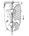
- FIGS. 1, 2 and 3 there is shown a tractor 10 having a frame 12 in which are journaled two sprockets one of which 14 is illustrated in detail.
- the sprockets are journaled in the frame between the side plates 16 and 18 thereof.
- the sprocket 14 is driven by a drive shaft.
- the tractor is clamped on a support shaft by a floating collet clamp mechanism 20.
- a lid 22 is pivotally mounted on the frame by hinge assemblies 24.
- a belt 26 having pins 27 and lugs 28 (see FIG.
- the pitch of the belt is equal to the pitch of the perforations so that the web (the edge perforated paper 30) is driven with and by the belt as the sprocket 14 is rotated by the drive shaft.
- the drive shaft may be connected through suitable gearing, belting or other transmission means to a stepper motor for feeding the paper 30 stepwise at high acceleration and with high speed.
- the lid 22 may be flipped upwardly about the pins 25 of the hinge assembly 24 so as to enable the paper to be placed in the tractor with the pins 27 in the perforations 29.
- a surface 34 in the side plate 16 This surface 34 and a corresponding surface (not shown) are adjacent to the hinge assemblies 24.
- the lid, when turned down toward the belt 26 is yieldably biased by a spring 36.
- the pitch line of the belt is essentially at its feeding surface since the belt is very thin (say 5 mils). By convention the pitch line is in the center of the belt.
- the pitch line of the belt also corresponds to the pitch line of the sprocket 14.
- the linear path of the belt is defined by a support 32 in the frame. A portion of the path is curvilinear and extends around the sprocket. Both the lid 22 and the frame 12 extend beyond the sprockets and are spaced from each other by a lid gap (see FIG. 3).
- the lid gap is straight so that the paper 30 is maintained in a plane and tensioned between a pair of tractors 10 and 11 which drive the paper (see FIG. 5). So far described the tractor is of conventional design and generally of the type described in U.S.
- Patents 3,825,162 and 4,129,239 issued to Leo James H ubbard.
- the earlier patent may be referred to for information concerning the design of the tractor generally and the later Hubbard patent may be referred to for information respecting the design of the floating collet clamp mechanism 20 used therein.
- the lid 22 has a slot 38 through which the pins 27 may be viewed from the top of the tractor through the lid.
- the slot 38 continues as a blind slot outwardly toward the ends of the lid as shown at 40 in FIG. 3.
- the side of the lid defined by the inside wall 42 of the slot is formed with a rib 44.
- the lower surface of the rib 44 which faces the belt 26 defines the lid gap. This lower surface is shown at 48 in FIG. 4.
- the surface 48 extends along a linear path opposite to the region of the belt where the pins 27 enter and engage the perforations 29.
- the use and location of the rib 44 is critical, as described above, to the precision feeding of the paper 30 through the tractor.
- the surface 48 is located so that the paper 30 is at or substantially at the pitch line of the belt.
- the spacing between the upper or paper guide surfaces 50 and 52 of the side frames 16 and 18 and the bottom surface 48 of the rib is less than 10 mils. This spacing is enlarged in FIG. 4 to facilitate the illustration. The spacing may be such that the paper 30 is on the surface of the belt 26.
- the pressure on the lid 22 is relieved by reason of the yieldable connection of the lid to the frame provided by the spring 36.
- the spacing of the paper 30 assures that the perforations will engage the pins below the position of repose.
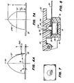
- the position of repose is determined by considering the pin surface as an inclined plane.
- the pin surface is preferably an involute which is defined by a radius, R (see FIG. 4A), which is equal to the diameter of the pin and in cross section has its center at the base of the pin where it contacts the flat, flexible portion of the belt 26.
- This portion is preferably made of polyamide such as Kapton (a trademark of the E.I. DuPont Company) but may be some other flexible material of suitable flexibility and tensile strength.
- the pin surface in cross section is essentially an involute in shape. It is almost a perfect involute to approximately 60% of the height of the tooth and then is slightly less steep than a perfect involute shape. As noted above such a substantially involute shape enables the pins to enter and leave the perforations in the paper 30 without significant ticking which may deform or tear the paper at the perforations.
- the effective force, F eff . (the reaction force of the paper against the pin which is perpendicular to the wall of the pin), will tend to hold and maintain the paper against the pin depending upon the coefficient of friction between the materials constituting the paper and the pin.
- the angle of repose, ⁇ defined by that position of repose may be determined by inclined plane principles to be equal to the tangent of the angle OC which is between the diameter and the surface of the belt as taken in cross section through the axis 50 of the pin.
- FIG. 4 shows two interference curves, one generated by the radius R 1 where the lid gap is such that the paper is substantially at the pitch line.
- Radius R 2 defines another interference curve shown in dash lines for the case where the paper is well above the pitch line for example with a conventional 35 to 40 mil lid gap.
- the critical position of repose may be determined by the product of the sine of the angle of repose ( ⁇ ) and the diameter of the pin R as will be apparent from FIG. 4A. Accordingly, based upon the criteria provided in accordance with the invention, a tractor may be designed so as to provide for accurate, precision feeding even at high speeds and accelerations.
- the driving forces F on the paper 30 produce components which tension the paper toward the center thereof. At high driving speeds and accelerations, these forces produce couples on the pins and tend to twist the belt. These forces are opposed by the thrust surface 42 provided by the inside wall of the lid slot 38. This wall is placed so that it is in contact with the surface of the pins along diameters through the pins which are perpendicular to the feeding direction of the paper and also perpendicular to the belt edges.
- While a single thrust surface wall 42 may be used, it may be desirable to extend the inside surface 54 of the slot 38 downwardly to define another rib 56 in addition to the rib 44 (see FIG. 8) then the pins are completely restrained against twisting.
- the surface 42 may be_extended outwardly as shown at 42A in F IG. 6.
- the pin 27A is truncated along the side thereof which engages the thrust surface provided by the wall 42A to approximately half-the height of the pin (h/2) as shown in FIG. 7A. Then a segment of approximately 60° to 90°, illustrated by the angle A in FIG. 7, is truncated from the pin shape. Since this angle is centered along a diameter perpendicular to the edge of the belt 26 and extends only 60° to 90°, less than 10% of the driving surface of the pin is affected.
- the invention may be summarized as follows:
Landscapes
- Handling Of Sheets (AREA)
- Advancing Webs (AREA)
Applications Claiming Priority (2)
| Application Number | Priority Date | Filing Date | Title |
|---|---|---|---|
| US06/721,100 US4611737A (en) | 1985-04-08 | 1985-04-08 | Tractor apparatus |
| US721100 | 1985-04-08 |
Publications (2)
| Publication Number | Publication Date |
|---|---|
| EP0200869A2 true EP0200869A2 (de) | 1986-11-12 |
| EP0200869A3 EP0200869A3 (de) | 1988-07-13 |
Family
ID=24896539
Family Applications (1)
| Application Number | Title | Priority Date | Filing Date |
|---|---|---|---|
| EP86102800A Withdrawn EP0200869A3 (de) | 1985-04-08 | 1986-03-04 | Traktorvorrichtung |
Country Status (3)
| Country | Link |
|---|---|
| US (1) | US4611737A (de) |
| EP (1) | EP0200869A3 (de) |
| JP (1) | JPS61287774A (de) |
Families Citing this family (10)
| Publication number | Priority date | Publication date | Assignee | Title |
|---|---|---|---|---|
| US4790467A (en) * | 1986-03-25 | 1988-12-13 | International Business Machines Corporation | Web feed mechanism and door with static protrusions |
| JPS62164261U (de) * | 1986-04-08 | 1987-10-19 | ||
| US4780013A (en) * | 1986-05-02 | 1988-10-25 | Sakase Kagaku Kogyo Kabushiki Kaisha | Web feed tractor for printer |
| US4706861A (en) * | 1986-09-30 | 1987-11-17 | Precision Handling Devices, Inc. | Perforated web feeding apparatus |
| JPH0533483Y2 (de) * | 1987-05-15 | 1993-08-25 | ||
| JPH01118947U (de) * | 1988-02-04 | 1989-08-11 | ||
| US4981244A (en) * | 1988-02-08 | 1991-01-01 | International Business Machines Corp. | Pin belt for movement of perforated strip |
| US4874121A (en) * | 1988-05-03 | 1989-10-17 | Output Technology Corporation | Web feed tractor belt assembly |
| US4955520A (en) * | 1989-03-24 | 1990-09-11 | Precision Handling Devices, Inc. | Web feed device having an improved lid mechanism |
| US5139190A (en) * | 1991-04-22 | 1992-08-18 | Precision Handling Devices Inc. | Document feed tractor with height adjustable web support surface |
Family Cites Families (9)
| Publication number | Priority date | Publication date | Assignee | Title |
|---|---|---|---|---|
| US3289904A (en) * | 1965-06-01 | 1966-12-06 | Potter Instrument Co Inc | Web feeding device having magnetic hold down means |
| US3825162A (en) * | 1973-02-20 | 1974-07-23 | L Hubbard | Feed mechanism |
| US4129239A (en) * | 1977-08-10 | 1978-12-12 | Precision Handling Devices, Inc. | Clamping devices for document tractors |
| US4130230A (en) * | 1977-10-31 | 1978-12-19 | Data Motion Incorporated | Sheet feed tractor |
| US4226353A (en) * | 1979-07-25 | 1980-10-07 | International Business Machines Corporation | Forms feed tractor |
| US4316567A (en) * | 1980-04-21 | 1982-02-23 | Teletype Corporation | Tractor for engaging and advancing a web of paper |
| JPS5867486A (ja) * | 1981-10-17 | 1983-04-22 | Ricoh Co Ltd | プリンタの用紙送りトラクタ |
| US4469263A (en) * | 1982-08-11 | 1984-09-04 | Data Motion, Inc. | Paper feed tractor with compensating drive pulley |
| US4471896A (en) * | 1983-10-19 | 1984-09-18 | Data Motion, Incorporated | Sheet-feed tractor with resilient spring clamping subassembly |
-
1985
- 1985-04-08 US US06/721,100 patent/US4611737A/en not_active Expired - Fee Related
-
1986
- 1986-03-04 EP EP86102800A patent/EP0200869A3/de not_active Withdrawn
- 1986-04-08 JP JP61080951A patent/JPS61287774A/ja active Pending
Also Published As
| Publication number | Publication date |
|---|---|
| EP0200869A3 (de) | 1988-07-13 |
| JPS61287774A (ja) | 1986-12-18 |
| US4611737A (en) | 1986-09-16 |
Similar Documents
| Publication | Publication Date | Title |
|---|---|---|
| US4611737A (en) | Tractor apparatus | |
| US4054235A (en) | Continuous forms sheet separator | |
| US4341480A (en) | Feed mechanism for continuous and cut form paper | |
| EP0166132B1 (de) | Drucker mit einem Zuführungssystem für mehrfache Wirkungsweise | |
| EP0798123A2 (de) | Mechanismus zum Führen von Endlos- und Einzelpapier für ein Bildaufzeichnungsgerät | |
| EP0181818A2 (de) | Blattzuführung für einen drehbaren Druckkopf | |
| EP0163933B1 (de) | Drucker mit integrierter Papierzuführvorrichtung | |
| EP0297486B1 (de) | Papierzuführvorrichtung für Drucker | |
| US4311401A (en) | Printing apparatus with inked ribbon lift restrainer | |
| US4925076A (en) | Paper feeder | |
| US5018887A (en) | Forms feed tractor having modified pin spacing | |
| US4706861A (en) | Perforated web feeding apparatus | |
| US4989771A (en) | Forms feeding apparatus | |
| US4473179A (en) | Pin feed mechanism for transporting continuous stationery | |
| US5139190A (en) | Document feed tractor with height adjustable web support surface | |
| US4714185A (en) | Perforated web feeding apparatus | |
| US5961233A (en) | Continuous paper cutting device for a thermal printer | |
| EP0359963A1 (de) | Formularvorschubziehvorrichtung | |
| EP0326393A1 (de) | Papierzuführmechanismus | |
| JPH0211175Y2 (de) | ||
| JPS58155977A (ja) | 紙送り装置 | |
| JPH0237565Y2 (de) | ||
| KR200146636Y1 (ko) | 프린터의 용지 선택 가압 장치 | |
| JP2855631B2 (ja) | プリンタの紙送り機構 | |
| JPH0131489Y2 (de) |
Legal Events
| Date | Code | Title | Description |
|---|---|---|---|
| PUAI | Public reference made under article 153(3) epc to a published international application that has entered the european phase |
Free format text: ORIGINAL CODE: 0009012 |
|
| AK | Designated contracting states |
Kind code of ref document: A2 Designated state(s): AT BE CH DE FR GB IT LI LU NL SE |
|
| RBV | Designated contracting states (corrected) |
Designated state(s): AT BE CH DE FR GB IT LI NL SE |
|
| PUAL | Search report despatched |
Free format text: ORIGINAL CODE: 0009013 |
|
| AK | Designated contracting states |
Kind code of ref document: A3 Designated state(s): AT BE CH DE FR GB IT LI NL SE |
|
| 17P | Request for examination filed |
Effective date: 19890112 |
|
| 17Q | First examination report despatched |
Effective date: 19900706 |
|
| STAA | Information on the status of an ep patent application or granted ep patent |
Free format text: STATUS: THE APPLICATION IS DEEMED TO BE WITHDRAWN |
|
| 18D | Application deemed to be withdrawn |
Effective date: 19921001 |
|
| RIN1 | Information on inventor provided before grant (corrected) |
Inventor name: KERIVAN, LEO J. Inventor name: HUBBARD, JOHN D. |