EP0200858B1 - Method and apparatus for removing substances adhering to surface - Google Patents
Method and apparatus for removing substances adhering to surface Download PDFInfo
- Publication number
- EP0200858B1 EP0200858B1 EP86102460A EP86102460A EP0200858B1 EP 0200858 B1 EP0200858 B1 EP 0200858B1 EP 86102460 A EP86102460 A EP 86102460A EP 86102460 A EP86102460 A EP 86102460A EP 0200858 B1 EP0200858 B1 EP 0200858B1
- Authority
- EP
- European Patent Office
- Prior art keywords
- nozzle
- nozzles
- nozzle head
- water
- nozzle tip
- Prior art date
- Legal status (The legal status is an assumption and is not a legal conclusion. Google has not performed a legal analysis and makes no representation as to the accuracy of the status listed.)
- Expired - Lifetime
Links
Images



Classifications
-
- E—FIXED CONSTRUCTIONS
- E04—BUILDING
- E04G—SCAFFOLDING; FORMS; SHUTTERING; BUILDING IMPLEMENTS OR AIDS, OR THEIR USE; HANDLING BUILDING MATERIALS ON THE SITE; REPAIRING, BREAKING-UP OR OTHER WORK ON EXISTING BUILDINGS
- E04G23/00—Working measures on existing buildings
- E04G23/002—Arrangements for cleaning building facades
-
- B—PERFORMING OPERATIONS; TRANSPORTING
- B05—SPRAYING OR ATOMISING IN GENERAL; APPLYING FLUENT MATERIALS TO SURFACES, IN GENERAL
- B05B—SPRAYING APPARATUS; ATOMISING APPARATUS; NOZZLES
- B05B1/00—Nozzles, spray heads or other outlets, with or without auxiliary devices such as valves, heating means
- B05B1/14—Nozzles, spray heads or other outlets, with or without auxiliary devices such as valves, heating means with multiple outlet openings; with strainers in or outside the outlet opening
-
- B—PERFORMING OPERATIONS; TRANSPORTING
- B05—SPRAYING OR ATOMISING IN GENERAL; APPLYING FLUENT MATERIALS TO SURFACES, IN GENERAL
- B05B—SPRAYING APPARATUS; ATOMISING APPARATUS; NOZZLES
- B05B1/00—Nozzles, spray heads or other outlets, with or without auxiliary devices such as valves, heating means
- B05B1/14—Nozzles, spray heads or other outlets, with or without auxiliary devices such as valves, heating means with multiple outlet openings; with strainers in or outside the outlet opening
- B05B1/1421—Nozzles, spray heads or other outlets, with or without auxiliary devices such as valves, heating means with multiple outlet openings; with strainers in or outside the outlet opening the multiple outlet openings arranged in plural groups or rows
- B05B1/1423—Nozzles, spray heads or other outlets, with or without auxiliary devices such as valves, heating means with multiple outlet openings; with strainers in or outside the outlet opening the multiple outlet openings arranged in plural groups or rows comprising concentric or coaxial groups
-
- B—PERFORMING OPERATIONS; TRANSPORTING
- B05—SPRAYING OR ATOMISING IN GENERAL; APPLYING FLUENT MATERIALS TO SURFACES, IN GENERAL
- B05B—SPRAYING APPARATUS; ATOMISING APPARATUS; NOZZLES
- B05B13/00—Machines or plants for applying liquids or other fluent materials to surfaces of objects or other work by spraying, not covered by groups B05B1/00 - B05B11/00
- B05B13/02—Means for supporting work; Arrangement or mounting of spray heads; Adaptation or arrangement of means for feeding work
- B05B13/04—Means for supporting work; Arrangement or mounting of spray heads; Adaptation or arrangement of means for feeding work the spray heads being moved during spraying operation
- B05B13/0421—Means for supporting work; Arrangement or mounting of spray heads; Adaptation or arrangement of means for feeding work the spray heads being moved during spraying operation with rotating spray heads
-
- B—PERFORMING OPERATIONS; TRANSPORTING
- B05—SPRAYING OR ATOMISING IN GENERAL; APPLYING FLUENT MATERIALS TO SURFACES, IN GENERAL
- B05B—SPRAYING APPARATUS; ATOMISING APPARATUS; NOZZLES
- B05B15/00—Details of spraying plant or spraying apparatus not otherwise provided for; Accessories
- B05B15/14—Arrangements for preventing or controlling structural damage to spraying apparatus or its outlets, e.g. for breaking at desired places; Arrangements for handling or replacing damaged parts
- B05B15/16—Arrangements for preventing or controlling structural damage to spraying apparatus or its outlets, e.g. for breaking at desired places; Arrangements for handling or replacing damaged parts for preventing non-intended contact between spray heads or nozzles and foreign bodies, e.g. nozzle guards
-
- B—PERFORMING OPERATIONS; TRANSPORTING
- B05—SPRAYING OR ATOMISING IN GENERAL; APPLYING FLUENT MATERIALS TO SURFACES, IN GENERAL
- B05B—SPRAYING APPARATUS; ATOMISING APPARATUS; NOZZLES
- B05B3/00—Spraying or sprinkling apparatus with moving outlet elements or moving deflecting elements
- B05B3/02—Spraying or sprinkling apparatus with moving outlet elements or moving deflecting elements with rotating elements
-
- B—PERFORMING OPERATIONS; TRANSPORTING
- B05—SPRAYING OR ATOMISING IN GENERAL; APPLYING FLUENT MATERIALS TO SURFACES, IN GENERAL
- B05B—SPRAYING APPARATUS; ATOMISING APPARATUS; NOZZLES
- B05B3/00—Spraying or sprinkling apparatus with moving outlet elements or moving deflecting elements
- B05B3/02—Spraying or sprinkling apparatus with moving outlet elements or moving deflecting elements with rotating elements
- B05B3/025—Rotational joints
- B05B3/026—Rotational joints the fluid passing axially from one joint element to another
-
- B—PERFORMING OPERATIONS; TRANSPORTING
- B05—SPRAYING OR ATOMISING IN GENERAL; APPLYING FLUENT MATERIALS TO SURFACES, IN GENERAL
- B05B—SPRAYING APPARATUS; ATOMISING APPARATUS; NOZZLES
- B05B9/00—Spraying apparatus for discharge of liquids or other fluent material, without essentially mixing with gas or vapour
- B05B9/01—Spray pistols, discharge devices
-
- B—PERFORMING OPERATIONS; TRANSPORTING
- B08—CLEANING
- B08B—CLEANING IN GENERAL; PREVENTION OF FOULING IN GENERAL
- B08B3/00—Cleaning by methods involving the use or presence of liquid or steam
- B08B3/02—Cleaning by the force of jets or sprays
- B08B3/026—Cleaning by making use of hand-held spray guns; Fluid preparations therefor
- B08B3/028—Spray guns
-
- Y—GENERAL TAGGING OF NEW TECHNOLOGICAL DEVELOPMENTS; GENERAL TAGGING OF CROSS-SECTIONAL TECHNOLOGIES SPANNING OVER SEVERAL SECTIONS OF THE IPC; TECHNICAL SUBJECTS COVERED BY FORMER USPC CROSS-REFERENCE ART COLLECTIONS [XRACs] AND DIGESTS
- Y10—TECHNICAL SUBJECTS COVERED BY FORMER USPC
- Y10S—TECHNICAL SUBJECTS COVERED BY FORMER USPC CROSS-REFERENCE ART COLLECTIONS [XRACs] AND DIGESTS
- Y10S239/00—Fluid sprinkling, spraying, and diffusing
- Y10S239/19—Nozzle materials
Definitions
- the invention relates to a method for removing substances adhering on a surface of the type mentioned in the preamble of the patent claim 1 and further relates to a nozzle structure for use in the method (preamble of claim 4).
- a nozzle structure for use in a spraying apparatus which comprises a nozzle tip formed with an opening having a reduced diameter portion and a tapering portion, nozzle tip holding members fitted in a recess formed in a nozzle head for holding the nozzle tip and a nut for fixing the nozzle tip in a position within the recess.
- the external wall of a building gets dirt or contaminated by dust contained in air or rain with the passage of time.
- the wall is needed to be renovated, for example by re-painting, every ten years or so.
- the wall should be washed every two or three years to remove dirt thereon.
- Washing of the wall is generally carried out by using water or washing chemicals.
- water When water is used, relatively high-pressure water of about 40 to 200 kp/cm 2 is jetted through a nozzle having a diameter of about 2 mm at a flow rate of 25 to 45 I/min.
- Stripping or peeling of the coating of the wall is carried out by using a sander, a chip-cleaner or a concrete-planer. Alternatively, chemicals are also used for stripping or peeling.
- Sanding or planing can effectively remove dirt or contaminant on the wall together with a surface thereof, but it has such a fatal defect that it makes dust, compromising the safety of the operator and contaminating the surroundings. If water is used in sanding or planing to prevent dusting, the sander or planer will be clogged and the operation efficiency will be lowered.
- the method using high-pressure water is free from the problems as described above and it is advantageous in that water can be easily obtained at low cost.
- the conventional method of this type is not satisfactory in that water is only jetted from a single nozzle and therefore washing or stripping is only made linearly when the nozzle is moved. Thus, the operation efficiency is extremely low.
- the present invention may be applied to washing of an outer wall of buildings or the like for removal of dirt or contaminant, stripping or peeling of coatings such as Lithine or paints, removing of deteriorated sprayed tiles, removing of concrete dust or removing of scale or rust of steel plates.
- the invention may further be applied to removal of burr on an inner wall of a tank.
- the holder 10 is a holder which is substantially cylindrical.
- the holder 10 comprises a front portion 10A and a rear portion 10B which are coupled by a bolt 12 in a position for use but they are disengageable from each other according to necessity, for example, when the holder is required to be repaired.
- the front portion 10A has a handle 14 provided integrally therewith at a lower portion thereof.
- a revolving follower-gear 16 is supported by bearings 18A and 18B and adapted to be rotated around its axis.
- the revolving follower gear 16 is provided with a liquid feed pipe 20 having an axis C2 at a position deviated for example by 5 mm from the axis C1 of the holder 10 and the liquid feeding pipe 20 is supported by bearings 22 and 24.
- An attachment 26 is integrally secured to the forward end of the liquid feeding pipe 20 through a thrust bearing 28.
- a nozzle head 30 as will be described in detail later is connected integrally with the attachment 26 in such a manner that its axis may be aligned with the axis C2.
- the rear end of the liquid feeding pipe 20 is coupled through a semi-spherical seat 20a to a flexible tube 32 which is in turn connected to an external pump (not shown) for high-pressure water W.
- 34 is a holding member for holding the coupling portion.
- the rear end of the flexible tube 32 is fixed in a protection pipe 36 mounted on the rear portion 10B of the holder 10 through a bush 38 and a securing nut 40.
- the air motor 42 is an air motor driven by air ai.
- the air motor is adapted to be held by a right hand of an operator and cooperates with the handle 14 to be held by a left hand of the operator to support the entire structure of the holder 10.
- the air motor 42 includes a switch 44 and it is coupled to the protection pipe 36 by a mounting bracket 46.
- a prime gear 50 Within the space 48 is rotatably supported a prime gear 50 by bearings 52 and 54.
- the output shaft of the air motor 42 and the prime gear 50 are coupled by a connecting rod 56 and the prime gear 50 is in mesh with the follower gear 16.
- the front end of the holder 10 is protected by a flexible cover 58 made of a flexible material such as rubber for preventing rebound of dust from the surface being treated.
- the nozzle head 30 is also protected by a cover 60.
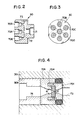
- a plurality of nozzles 70A, 70B ..., for example, seven nozzles are provided on the nozzle head as illustrated in Figs. 2 and 3.
- one nozzle is at a center and the remaining six nozzles are disposed at angular intervals of 60 so as to surround the center one.
- the nozzle head 30 has, at a central portion thereof, an inlet 71 communicating with the liquid feeding pipe 20, communicating passages 72 extending radially therefrom and introducing passages 73 communicating therewith.
- each of the nozzles 70A, 70B ... is communicated with the liquid feeding pipe 20 forming a liquid feeding path.
- the nozzle comprises a nozzle tip 70a of diamond fitted in a hole 30a which is formed on the nozzle head 30 made of a titanium alloy.
- the nozzle tip 70a is held by holding pieces 70b, 70c made of a monel metal and fixed in a position by a nut 74 made of stainless steel and having a hexagonal hole.
- the thickness T of the nozzle tip 70a is, for example, 0.5 to 2 mm and more preferably 0.5 to 1.5 mm and it has an opening having a reduced diameter portion where the diameter D is about 0.15 mm and a tapering portion where the opening has an angle 6 of 25 to 55°, preferably 35 to 45°.
- the length I of the reduced diameter portion is preferably 1/2T ⁇ I Z 2/3T. In case the length I is larger than 2/3T, there may be caused turbulent flow and in case the length I is smaller than 1/2T, the nozzle tip 70a is liable to be worn out.
- the angle 6 of the opening is larger than 55°, water jetted through the nozzle is atomized and the energy of water per unit area is lowered.
- the angle is smaller than 25°, not only water jetted through the nozzle becomes turbulent, but the operation efficiency is lowered.
- the pressure of water fed to each of the nozzles 70A, 70B ... is above 800 kg/cm 2 and preferably 1000 kg/cm 2 or more.
- the loci of jetted water are as shown in Fig. 5.
- the loci of the nozzles 70F and 70G are omitted.
- the high-pressure water acts all over the surface to be treated and washing and peeling of the substances adhering thereto may be attained over a wide area.
- the number of the nozzles on the nozzle head is not critical and it may be selected according to necessity. It may, for example, be seven as illustrated in Fig. 3, twelve as illustrated in Fig. 7 and twenty as illustrated in Fig. 8. However, the positions of the nozzles may be selected in relation with the distance of the deviation so that the locus of each of the nozzles may overlap as illustrated in Fig. 6.
- the diameter D of the nozzles, the pressure P of water, the amount q of jet flow per nozzle, the amount Q of total jet flow and the number R of revolutions of the nozzle head are selected so as to be within the following ranges.
- the optimum ranges are denoted within the parentheses.
- the diameter D of the nozzle, the jet flow q per nozzle and the total jet flow Q have relationships as shown in Figs. 9 and 10.
- the nozzle diameter D is smaller than the specified limit, the jet energy is too small to obtain sufficient washing and peeling effects even if the pressure of water is raised.
- clog may possibly be caused at a nozzle, especially at a nozzle tip.
- the diameter D is larger than the specified limit, the flow q and Q become too large for an operator to hold the apparatus by hand and too large to drain without a draining system.
- the pressure P is small, the washing and peeling effects are insufficient and in case the pressure P is large, desired washing and peeling effects can be obtained.
- the reacting force caused by jetting of water onto the surface to be treated acts on the holder 10.
- Q is about 5 I and the reaction force is about 9.5 kg.
- the weight of the apparatus is about 5 kg.
- the weight including the reaction which the operator can hold safely is about 15 kg.
- the total weight should be considered.
- the holder 10 is mounted on a machine or the holder itself is a part of the machine, the reaction may be larger.
- the nozzle head having a plurality of unit nozzles is revoluted eccentrically, whereby washing or peeling can be effected over a wide area at a time as shown in Fig. 6.
- This feature is different from the conventional technique in which washing or peeling is effected only linearly.
- Another characteristic feature of the present invention lies in that a small amount of water is jetted at an extremely high pressure.
- a large amount of water is jetted through a nozzle of large diameter at a pressure of 40 to 200 kg/cm 2 .
- the effect of washing, especially effect of peeling is rather small for the amount of water used.
- the consumption of large amount of water brings further disadvantages that the operation efficiency is lowered and that water drainage system is needed.
Landscapes
- Engineering & Computer Science (AREA)
- Architecture (AREA)
- Chemical & Material Sciences (AREA)
- Chemical Kinetics & Catalysis (AREA)
- Electrochemistry (AREA)
- Mechanical Engineering (AREA)
- Civil Engineering (AREA)
- Structural Engineering (AREA)
- Nozzles (AREA)
- Cleaning By Liquid Or Steam (AREA)
- Mechanical Treatment Of Semiconductor (AREA)
- Cleaning In General (AREA)
Abstract
Description
- The invention relates to a method for removing substances adhering on a surface of the type mentioned in the preamble of the patent claim 1 and further relates to a nozzle structure for use in the method (preamble of claim 4).
- With such a method known from the DE-A-3 234 419 the water pressure to be supplied to each of the unit nozzles is 1000 bar.
- Furthermore from the CH-A-567 907 a nozzle structure for use in a spraying apparatus is known which comprises a nozzle tip formed with an opening having a reduced diameter portion and a tapering portion, nozzle tip holding members fitted in a recess formed in a nozzle head for holding the nozzle tip and a nut for fixing the nozzle tip in a position within the recess.
- The external wall of a building gets dirt or contaminated by dust contained in air or rain with the passage of time. In general, the wall is needed to be renovated, for example by re-painting, every ten years or so. In case of a special kind of wall such as a so-called curtain wall, the wall should be washed every two or three years to remove dirt thereon. Or, as the case may be, there is a need for stripping a coating on the wall to expose a surface thereof.
- Washing of the wall is generally carried out by using water or washing chemicals. When water is used, relatively high-pressure water of about 40 to 200 kp/cm2 is jetted through a nozzle having a diameter of about 2 mm at a flow rate of 25 to 45 I/min.
- Stripping or peeling of the coating of the wall is carried out by using a sander, a chip-cleaner or a concrete-planer. Alternatively, chemicals are also used for stripping or peeling.
- However, these conventional methods have various disadvantages. When chemicals are used in washing, there is no problem of dusting, but the chemicals usually contain acids and they give undesirable influence upon plants on the ground and possibly deteriorate or change the properties of the surface of the wall.
- Sanding or planing can effectively remove dirt or contaminant on the wall together with a surface thereof, but it has such a fatal defect that it makes dust, compromising the safety of the operator and contaminating the surroundings. If water is used in sanding or planing to prevent dusting, the sander or planer will be clogged and the operation efficiency will be lowered.
- In contrast, the method using high-pressure water is free from the problems as described above and it is advantageous in that water can be easily obtained at low cost. However, the conventional method of this type is not satisfactory in that water is only jetted from a single nozzle and therefore washing or stripping is only made linearly when the nozzle is moved. Thus, the operation efficiency is extremely low.
- It is therefore the object of the present invention to provide a method for removing substances adhering of a surface of the type mentioned in the preamble of the patent claim 1 which is excellent in operation efficiency and free from dusting which assures the safety of the operator.
- According to the present invention this is obtained by the steps mentioned in the characterizing part of the patent claim 1.
- Preferred embodiments of the method according to the present invention are subject matter of the patent claims 2 and 3. A nozzle structure for use in an apparatus for removing substances adhering on a surface in the method of the invention is subject matter of claim 4.
- The present invention may be applied to washing of an outer wall of buildings or the like for removal of dirt or contaminant, stripping or peeling of coatings such as Lithine or paints, removing of deteriorated sprayed tiles, removing of concrete dust or removing of scale or rust of steel plates. The invention may further be applied to removal of burr on an inner wall of a tank.
- Fig. 1 is a longitudinal sectional view of an apparatus embodying the present invention;
- Fig. 2 is a sectional view of a nozzle head employable in the present invention;
- Fig. 3 is a left side elevational view of the nozzle head of Fig. 2;
- Fig. 4 is a detailed sectional view of a nozzle provided in the nozzle head;
- Fig. 5 shows loci of nozzles when the nozzle head is held at a position;
- Fig. 6 shows loci of nozzles when the nozzle head is moved sidewardly;
- Figs. 7 and 8 are front side elevational views of alternative nozzle heads, respectively; and
- Figs. 9 and 10 are graphs showing the relationships between the nozzle diameter and the flow rate.
- The invention will be described in detail referring to the drawings.
- The structure of an apparatus embodying the present invention will be first described.
- 10 is a holder which is substantially cylindrical. The
holder 10 comprises a front portion 10A and arear portion 10B which are coupled by abolt 12 in a position for use but they are disengageable from each other according to necessity, for example, when the holder is required to be repaired. The front portion 10A has a handle 14 provided integrally therewith at a lower portion thereof. Within the front portion 10A, a revolving follower-gear 16 is supported bybearings follower gear 16 is provided with aliquid feed pipe 20 having an axis C2 at a position deviated for example by 5 mm from the axis C1 of theholder 10 and theliquid feeding pipe 20 is supported bybearings attachment 26 is integrally secured to the forward end of theliquid feeding pipe 20 through a thrust bearing 28. Anozzle head 30 as will be described in detail later is connected integrally with theattachment 26 in such a manner that its axis may be aligned with the axis C2. - The rear end of the
liquid feeding pipe 20 is coupled through a semi-spherical seat 20a to aflexible tube 32 which is in turn connected to an external pump (not shown) for high-pressure water W. 34 is a holding member for holding the coupling portion. The rear end of theflexible tube 32 is fixed in aprotection pipe 36 mounted on therear portion 10B of theholder 10 through abush 38 and asecuring nut 40. - 42 is an air motor driven by air ai. The air motor is adapted to be held by a right hand of an operator and cooperates with the handle 14 to be held by a left hand of the operator to support the entire structure of the
holder 10. Theair motor 42 includes aswitch 44 and it is coupled to theprotection pipe 36 by amounting bracket 46. There remains aspace 48 between the front portion 10A and therear portion 10B of theholder 10. Within thespace 48 is rotatably supported aprime gear 50 bybearings air motor 42 and theprime gear 50 are coupled by a connecting rod 56 and theprime gear 50 is in mesh with thefollower gear 16. - The front end of the
holder 10 is protected by a flexible cover 58 made of a flexible material such as rubber for preventing rebound of dust from the surface being treated. Thenozzle head 30 is also protected by acover 60. - With this arrangement, when high-pressure water W is fed to the
flexible tube 32 through the pump, the water W passes through theliquid feeding pipe 20 to thenozzle head 30 through which water is jetted onto the surface to be treated. At this time, theair motor 42 is rotated and thefollower gear 16 is rotated through theprime gear 50. Since thefollower gear 16 has theliquid feeding pipe 20 at a position deviated from the axis C1 of theholder 10, thenozzle head 30 is revolved around the axis C1 as illustrated in Fig. 5. The forward portion of theflexible shaft 32 is revolved following the revolution of thenozzle head 30. The shaking of the nozzle head caused at this time is absorbed by thebearings - According to the present invention, a plurality of
nozzles nozzle head 30 has, at a central portion thereof, aninlet 71 communicating with theliquid feeding pipe 20, communicatingpassages 72 extending radially therefrom and introducingpassages 73 communicating therewith. Thus, each of thenozzles liquid feeding pipe 20 forming a liquid feeding path. - The details of each of the nozzles are illustrated in Fig. 4. For example, the nozzle comprises a nozzle tip 70a of diamond fitted in a hole 30a which is formed on the
nozzle head 30 made of a titanium alloy. The nozzle tip 70a is held byholding pieces 70b, 70c made of a monel metal and fixed in a position by anut 74 made of stainless steel and having a hexagonal hole. - The thickness T of the nozzle tip 70a is, for example, 0.5 to 2 mm and more preferably 0.5 to 1.5 mm and it has an opening having a reduced diameter portion where the diameter D is about 0.15 mm and a tapering portion where the opening has an angle 6 of 25 to 55°, preferably 35 to 45°. The length I of the reduced diameter portion is preferably 1/2T ≦ I Z 2/3T. In case the length I is larger than 2/3T, there may be caused turbulent flow and in case the length I is smaller than 1/2T, the nozzle tip 70a is liable to be worn out. When the angle 6 of the opening is larger than 55°, water jetted through the nozzle is atomized and the energy of water per unit area is lowered. When the angle is smaller than 25°, not only water jetted through the nozzle becomes turbulent, but the operation efficiency is lowered.
- In the present invention, the pressure of water fed to each of the
nozzles nozzle head 30 is being revolved as illustrated in Fig. 5, the loci of jetted water are as shown in Fig. 5. In this state, when thenozzle head 30 is moved sidewardly, the loci become as illustrated in Fig. 6. In the figure, the loci of thenozzles 70F and 70G are omitted. Thus, the high-pressure water acts all over the surface to be treated and washing and peeling of the substances adhering thereto may be attained over a wide area. - The number of the nozzles on the nozzle head is not critical and it may be selected according to necessity. It may, for example, be seven as illustrated in Fig. 3, twelve as illustrated in Fig. 7 and twenty as illustrated in Fig. 8. However, the positions of the nozzles may be selected in relation with the distance of the deviation so that the locus of each of the nozzles may overlap as illustrated in Fig. 6.
- The diameter D of the nozzles, the pressure P of water, the amount q of jet flow per nozzle, the amount Q of total jet flow and the number R of revolutions of the nozzle head are selected so as to be within the following ranges. The optimum ranges are denoted within the parentheses.


- The diameter D of the nozzle, the jet flow q per nozzle and the total jet flow Q have relationships as shown in Figs. 9 and 10. In case the nozzle diameter D is smaller than the specified limit, the jet energy is too small to obtain sufficient washing and peeling effects even if the pressure of water is raised. In addition, clog may possibly be caused at a nozzle, especially at a nozzle tip. In case the diameter D is larger than the specified limit, the flow q and Q become too large for an operator to hold the apparatus by hand and too large to drain without a draining system. In case the pressure P is small, the washing and peeling effects are insufficient and in case the pressure P is large, desired washing and peeling effects can be obtained. However, in the latter case, there are such disadvantages that the wearing of the nozzle tip is large and therefore the material of the nozzle tip should be selected so as to have sufficient strength to tolerate the wearing. If the number R of revolutions is small, each of the nozzles stays at one position long, which results in harming the surface and lowering of operation efficiency. Whereas, if the number R of the revolutions is too large, the strength of the member for eccentrically holding the water feeding pipe cannot be assured.
- However, if Q or P is raised, the reacting force caused by jetting of water onto the surface to be treated acts on the
holder 10. When the nozzle head has seven nozzles each having a diameter D = 0.2 mm, Q is about 5 I and the reaction force is about 9.5 kg. The weight of the apparatus is about 5 kg. In this connection, it is to be noted that the weight including the reaction which the operator can hold safely is about 15 kg. Thus, there is a limit in weight which the operator can support with safety and therefore the total weight should be considered. However, if theholder 10 is mounted on a machine or the holder itself is a part of the machine, the reaction may be larger. - As described above, according to the present invention, the nozzle head having a plurality of unit nozzles is revoluted eccentrically, whereby washing or peeling can be effected over a wide area at a time as shown in Fig. 6. This feature is different from the conventional technique in which washing or peeling is effected only linearly.
- Another characteristic feature of the present invention lies in that a small amount of water is jetted at an extremely high pressure. In a conventional technique, a large amount of water is jetted through a nozzle of large diameter at a pressure of 40 to 200 kg/cm2. However, the effect of washing, especially effect of peeling is rather small for the amount of water used. The consumption of large amount of water brings further disadvantages that the operation efficiency is lowered and that water drainage system is needed.
- In contrast, according to the present invention, small amount of water is jetted at an extremely high pressure, so that the jet stream from each of the nozzles strongly taps the surface to be treated. Thus, large effect of washing and peeling can be obtained. Furthermore, plurality of such jet streams are provided from the nozzle head which is rotated at a rate as high as 800 to 4000 rpm. As a result, the washing and peeling effects can be easily spread all over the surface. Thus, operation efficiency can be improved.
Claims (4)
Priority Applications (1)
| Application Number | Priority Date | Filing Date | Title |
|---|---|---|---|
| AT86102460T ATE57980T1 (en) | 1985-04-02 | 1986-02-25 | METHOD AND EQUIPMENT FOR REMOVING SUBSTANCES ADHERED TO SURFACE. |
Applications Claiming Priority (2)
| Application Number | Priority Date | Filing Date | Title |
|---|---|---|---|
| JP70561/85 | 1985-04-02 | ||
| JP60070561A JPH0737199B2 (en) | 1985-04-02 | 1985-04-02 | How to remove surface deposits |
Publications (3)
| Publication Number | Publication Date |
|---|---|
| EP0200858A2 EP0200858A2 (en) | 1986-11-12 |
| EP0200858A3 EP0200858A3 (en) | 1987-08-05 |
| EP0200858B1 true EP0200858B1 (en) | 1990-10-31 |
Family
ID=13435065
Family Applications (1)
| Application Number | Title | Priority Date | Filing Date |
|---|---|---|---|
| EP86102460A Expired - Lifetime EP0200858B1 (en) | 1985-04-02 | 1986-02-25 | Method and apparatus for removing substances adhering to surface |
Country Status (6)
| Country | Link |
|---|---|
| US (1) | US4806172A (en) |
| EP (1) | EP0200858B1 (en) |
| JP (1) | JPH0737199B2 (en) |
| AT (1) | ATE57980T1 (en) |
| DE (1) | DE3675250D1 (en) |
| SG (1) | SG47692G (en) |
Families Citing this family (31)
| Publication number | Priority date | Publication date | Assignee | Title |
|---|---|---|---|---|
| DE3643446A1 (en) * | 1986-12-19 | 1988-06-30 | Henkel Kgaa | METHOD FOR DETACHING A GLUED COATING AND DEVICE FOR CARRYING OUT THE METHOD |
| JP2668696B2 (en) * | 1988-03-04 | 1997-10-27 | 大成建設株式会社 | Method to prevent peeling and scattering of asbestos-containing substances |
| FR2643673B1 (en) * | 1989-02-24 | 1991-06-14 | Diat Christian | FACADE CLEANING DEVICE |
| US5078161A (en) * | 1989-05-31 | 1992-01-07 | Flow International Corporation | Airport runway cleaning method |
| US5220935A (en) * | 1990-12-28 | 1993-06-22 | Carolina Equipment & Supply Co., Inc. | Apparatus and method for cleaning with a focused fluid stream |
| US5263504A (en) * | 1990-12-28 | 1993-11-23 | Carolina Equipment And Supply Company, Inc. | Apparatus and method for cleaning with a focused fluid stream |
| JP3073261B2 (en) * | 1991-06-03 | 2000-08-07 | 株式会社ジェイエスイー | Stone surface processing method and device |
| JPH0796360B2 (en) * | 1991-11-02 | 1995-10-18 | 太平商工株式会社 | Coating film peeling device |
| CZ285789B6 (en) * | 1991-12-11 | 1999-11-17 | Christian Diat | Apparatus for micro-cleaning of surfaces |
| CA2135173A1 (en) * | 1992-05-20 | 1993-11-25 | Bruce E. Witzel | Ester derivatives of 4-aza-steroids |
| US7299732B1 (en) * | 1994-10-24 | 2007-11-27 | United Technologies Corporation | Honeycomb removal |
| US5617886A (en) * | 1995-03-01 | 1997-04-08 | Mathieus; George J. | Rotating nozzle |
| US5647201A (en) * | 1995-08-02 | 1997-07-15 | Trw Inc. | Cavitating venturi for low reynolds number flows |
| US5730358A (en) * | 1995-12-22 | 1998-03-24 | Flow International Corporation | Tunable ultrahigh-pressure nozzle |
| GB9625892D0 (en) * | 1996-12-13 | 1997-01-29 | Cooper Brett | Fluid gun |
| US5855219A (en) * | 1996-12-20 | 1999-01-05 | Spencer; Michael P. | Bottle washing apparatus |
| US6029746A (en) * | 1997-07-22 | 2000-02-29 | Vortech, Inc. | Self-excited jet stimulation tool for cleaning and stimulating wells |
| US6470980B1 (en) | 1997-07-22 | 2002-10-29 | Rex A. Dodd | Self-excited drill bit sub |
| US6675548B2 (en) * | 2000-08-31 | 2004-01-13 | Dyk Incorporated | Method and apparatus for texturizing tank walls |
| US7007865B2 (en) * | 2003-08-14 | 2006-03-07 | Rex A. Dodd | Self-adjusting nozzle |
| US7744021B2 (en) * | 2006-03-09 | 2010-06-29 | Belanger, Inc. | Carwash spray nozzle and washing system using same |
| JP5110990B2 (en) * | 2007-07-12 | 2012-12-26 | 鹿島建設株式会社 | Asbestos removal method |
| US9180496B2 (en) * | 2008-02-28 | 2015-11-10 | Waterblasting, Llc | Water blasting head with through feeding hydraulic motor |
| JP2013120025A (en) * | 2011-12-08 | 2013-06-17 | Nisshin Kiko Kk | Repairing method of heat transfer tube |
| US9908068B2 (en) | 2012-02-14 | 2018-03-06 | Waterblasting, Llc | Water and debris recovery system |
| FR3002863A1 (en) | 2013-03-07 | 2014-09-12 | Air Liquide | DEVICE FOR DISPENSING CRYOGENIC FLUID JETS WITH FLEXIBLE PROTECTIVE ENVELOPE |
| ES2874531T3 (en) * | 2015-05-29 | 2021-11-05 | Medaxis Ag | Nozzle element for projecting a jet of water |
| BR112018007219A2 (en) * | 2015-11-12 | 2018-10-16 | Halliburton Energy Services Inc | system and method of injecting a chemical |
| BE1023188B1 (en) * | 2015-11-26 | 2016-12-14 | Depannage Service Bvba | METHOD AND DEVICE FOR CLEANING SURFACES AND / OR PANELS LIKE FORMWORK PANELS |
| CH714354A2 (en) * | 2017-11-17 | 2019-05-31 | Mvt Micro Verschleiss Technik Ag | A fluid jet nozzle device, method of manufacturing a nozzle device, and kit comprising a rotor and a hollow needle for a nozzle device. |
| WO2020150601A1 (en) * | 2019-01-19 | 2020-07-23 | Waterblasting, Llc | Grinder head |
Family Cites Families (13)
| Publication number | Priority date | Publication date | Assignee | Title |
|---|---|---|---|---|
| BE400210A (en) * | ||||
| US1919027A (en) * | 1932-01-23 | 1933-07-18 | May Oil Burner Corp | Atomizer |
| US3709436A (en) * | 1971-01-06 | 1973-01-09 | Heist Corp C H | High pressure jet cleaning device |
| CH567907A5 (en) * | 1973-02-22 | 1975-10-15 | Bendix Corp | Textile fluid jet cutter - nozzle geometry permitting formation of long lasting coherent cutting jet |
| JPS602489B2 (en) * | 1977-05-02 | 1985-01-22 | 株式会社豊田中央研究所 | Pressure fluid release device for low noise |
| DE2814165C2 (en) * | 1978-04-01 | 1980-04-30 | Bochumer Eisenhuette Heintzmann Gmbh & Co, 4630 Bochum | High pressure water nozzle |
| DE2906648C3 (en) * | 1979-02-21 | 1981-09-10 | Alfred Kärcher GmbH & Co, 7057 Winnenden | Spray nozzle arrangement for high pressure cleaning devices |
| JPS5711100A (en) * | 1980-06-26 | 1982-01-20 | Nochi Seikou Kk | Method and apparatus for exfoliating metallic body adhering substance and extra-high pressure water pump |
| US4369850B2 (en) * | 1980-07-28 | 1989-06-06 | High pressure fluid jet cutting and drilling apparatus | |
| DE3032191C2 (en) * | 1980-08-27 | 1986-11-20 | Heinrich-Josef 4840 Rheda-Wiedenbrück Lettmann | Device for cleaning the walls of tall structures |
| FR2506428A1 (en) * | 1981-05-22 | 1982-11-26 | Framatome Sa | METHOD AND DEVICE FOR DECOLMATING THE UPPER FACE OF THE TUBULAR PLATE OF A STEAM GENERATOR |
| FR2514108B1 (en) * | 1981-10-06 | 1986-06-13 | Framatome Sa | PROCESS AND DEVICE FOR REMOVING SLUDGE FROM THE TUBULAR PLATE OF STEAM GENERATORS |
| DE3234419A1 (en) * | 1982-09-16 | 1984-03-22 | Gabler Gmbh & Co Kg, 4230 Wesel | Rotational washing head |
-
1985
- 1985-04-02 JP JP60070561A patent/JPH0737199B2/en not_active Expired - Lifetime
- 1985-07-03 US US06/752,206 patent/US4806172A/en not_active Expired - Lifetime
-
1986
- 1986-02-25 AT AT86102460T patent/ATE57980T1/en active
- 1986-02-25 EP EP86102460A patent/EP0200858B1/en not_active Expired - Lifetime
- 1986-02-25 DE DE8686102460T patent/DE3675250D1/en not_active Expired - Fee Related
-
1992
- 1992-04-29 SG SG47692A patent/SG47692G/en unknown
Also Published As
| Publication number | Publication date |
|---|---|
| EP0200858A2 (en) | 1986-11-12 |
| ATE57980T1 (en) | 1990-11-15 |
| SG47692G (en) | 1992-06-12 |
| DE3675250D1 (en) | 1990-12-06 |
| US4806172A (en) | 1989-02-21 |
| EP0200858A3 (en) | 1987-08-05 |
| JPS61229000A (en) | 1986-10-13 |
| JPH0737199B2 (en) | 1995-04-26 |
Similar Documents
| Publication | Publication Date | Title |
|---|---|---|
| US4806172A (en) | Method and apparatus for removing substances adhering to surface | |
| JP5926196B2 (en) | Tools and methods for cleaning underwater surfaces | |
| DE68907234T2 (en) | Process for separating asbestos-containing material and preventing floating dust. | |
| US20020011259A1 (en) | Filter cleaning device and system | |
| KR102654015B1 (en) | The scale of the pipeline, the impurity removal device, and the cleaning method using it | |
| EP3749165A1 (en) | Manually guided surface cleaning device having a scrubbing brush roller unit | |
| KR20010006372A (en) | Method and device for cleaning piping with a vertical section | |
| CZ285789B6 (en) | Apparatus for micro-cleaning of surfaces | |
| KR100404053B1 (en) | Stripping apparatus and method for removing material from a surface | |
| US6219921B1 (en) | Chain saw guide bar with cleaning means | |
| US6789553B2 (en) | Coatings removal head assembly and method of use | |
| DE19735266C2 (en) | Device for high pressure cleaning of golf clubs with water | |
| EP0204655A2 (en) | Cleaning device for damping rollers | |
| JPH0825160B2 (en) | Surface deposit remover | |
| CN211948159U (en) | Highway concrete retaining wall cleaning machine | |
| KR100806543B1 (en) | Moss Removal Device for Sewage Treatment Plant | |
| US6604696B1 (en) | Ultra-high pressure water jet ring with angled nozzles and a conical dispersion pattern | |
| WO1993024717A1 (en) | Cleaning apparatus for roof plates | |
| JPH0791901B2 (en) | Equipment for peeling of concrete surfaces | |
| KR200410472Y1 (en) | Moss Removal Device for Sewage Treatment Plant | |
| KR100854699B1 (en) | Injector for water pipe tunnel regeneration automation. | |
| JPH02224975A (en) | Dust collecting type local treating device | |
| JPH0414087Y2 (en) | ||
| JPH07157996A (en) | Paper machine suction roll cleaning machine and paper machine suction roll cleaning method | |
| JPH0756166Y2 (en) | Hopper cleaning device |
Legal Events
| Date | Code | Title | Description |
|---|---|---|---|
| PUAI | Public reference made under article 153(3) epc to a published international application that has entered the european phase |
Free format text: ORIGINAL CODE: 0009012 |
|
| AK | Designated contracting states |
Kind code of ref document: A2 Designated state(s): AT BE CH DE FR GB IT LI NL SE |
|
| PUAL | Search report despatched |
Free format text: ORIGINAL CODE: 0009013 |
|
| AK | Designated contracting states |
Kind code of ref document: A3 Designated state(s): AT BE CH DE FR GB IT LI NL SE |
|
| 17P | Request for examination filed |
Effective date: 19871207 |
|
| RAP1 | Party data changed (applicant data changed or rights of an application transferred) |
Owner name: JSE CORPORATION |
|
| 17Q | First examination report despatched |
Effective date: 19881031 |
|
| GRAA | (expected) grant |
Free format text: ORIGINAL CODE: 0009210 |
|
| AK | Designated contracting states |
Kind code of ref document: B1 Designated state(s): AT BE CH DE FR GB IT LI NL SE |
|
| REF | Corresponds to: |
Ref document number: 57980 Country of ref document: AT Date of ref document: 19901115 Kind code of ref document: T |
|
| ITF | It: translation for a ep patent filed | ||
| REF | Corresponds to: |
Ref document number: 3675250 Country of ref document: DE Date of ref document: 19901206 |
|
| ET | Fr: translation filed | ||
| PLBE | No opposition filed within time limit |
Free format text: ORIGINAL CODE: 0009261 |
|
| STAA | Information on the status of an ep patent application or granted ep patent |
Free format text: STATUS: NO OPPOSITION FILED WITHIN TIME LIMIT |
|
| 26N | No opposition filed | ||
| ITTA | It: last paid annual fee | ||
| EAL | Se: european patent in force in sweden |
Ref document number: 86102460.2 |
|
| PGFP | Annual fee paid to national office [announced via postgrant information from national office to epo] |
Ref country code: SE Payment date: 19970212 Year of fee payment: 12 Ref country code: BE Payment date: 19970212 Year of fee payment: 12 |
|
| PGFP | Annual fee paid to national office [announced via postgrant information from national office to epo] |
Ref country code: CH Payment date: 19970217 Year of fee payment: 12 |
|
| PGFP | Annual fee paid to national office [announced via postgrant information from national office to epo] |
Ref country code: AT Payment date: 19970219 Year of fee payment: 12 |
|
| PGFP | Annual fee paid to national office [announced via postgrant information from national office to epo] |
Ref country code: NL Payment date: 19970228 Year of fee payment: 12 |
|
| PG25 | Lapsed in a contracting state [announced via postgrant information from national office to epo] |
Ref country code: AT Free format text: LAPSE BECAUSE OF NON-PAYMENT OF DUE FEES Effective date: 19980225 |
|
| PG25 | Lapsed in a contracting state [announced via postgrant information from national office to epo] |
Ref country code: SE Free format text: LAPSE BECAUSE OF NON-PAYMENT OF DUE FEES Effective date: 19980226 |
|
| PG25 | Lapsed in a contracting state [announced via postgrant information from national office to epo] |
Ref country code: LI Free format text: LAPSE BECAUSE OF NON-PAYMENT OF DUE FEES Effective date: 19980228 Ref country code: CH Free format text: LAPSE BECAUSE OF NON-PAYMENT OF DUE FEES Effective date: 19980228 Ref country code: BE Free format text: LAPSE BECAUSE OF NON-PAYMENT OF DUE FEES Effective date: 19980228 |
|
| BERE | Be: lapsed |
Owner name: JSE CORP. Effective date: 19980228 |
|
| PG25 | Lapsed in a contracting state [announced via postgrant information from national office to epo] |
Ref country code: NL Free format text: LAPSE BECAUSE OF NON-PAYMENT OF DUE FEES Effective date: 19980901 |
|
| REG | Reference to a national code |
Ref country code: CH Ref legal event code: PL |
|
| EUG | Se: european patent has lapsed |
Ref document number: 86102460.2 |
|
| NLV4 | Nl: lapsed or anulled due to non-payment of the annual fee |
Effective date: 19980901 |
|
| PGFP | Annual fee paid to national office [announced via postgrant information from national office to epo] |
Ref country code: DE Payment date: 19991231 Year of fee payment: 15 |
|
| PGFP | Annual fee paid to national office [announced via postgrant information from national office to epo] |
Ref country code: FR Payment date: 20000127 Year of fee payment: 15 |
|
| PGFP | Annual fee paid to national office [announced via postgrant information from national office to epo] |
Ref country code: GB Payment date: 20000207 Year of fee payment: 15 |
|
| PG25 | Lapsed in a contracting state [announced via postgrant information from national office to epo] |
Ref country code: GB Free format text: LAPSE BECAUSE OF NON-PAYMENT OF DUE FEES Effective date: 20010225 |
|
| GBPC | Gb: european patent ceased through non-payment of renewal fee |
Effective date: 20010225 |
|
| PG25 | Lapsed in a contracting state [announced via postgrant information from national office to epo] |
Ref country code: FR Free format text: LAPSE BECAUSE OF NON-PAYMENT OF DUE FEES Effective date: 20011031 |
|
| REG | Reference to a national code |
Ref country code: FR Ref legal event code: ST |
|
| PG25 | Lapsed in a contracting state [announced via postgrant information from national office to epo] |
Ref country code: DE Free format text: LAPSE BECAUSE OF NON-PAYMENT OF DUE FEES Effective date: 20011201 |
|
| PG25 | Lapsed in a contracting state [announced via postgrant information from national office to epo] |
Ref country code: IT Free format text: LAPSE BECAUSE OF NON-PAYMENT OF DUE FEES;WARNING: LAPSES OF ITALIAN PATENTS WITH EFFECTIVE DATE BEFORE 2007 MAY HAVE OCCURRED AT ANY TIME BEFORE 2007. THE CORRECT EFFECTIVE DATE MAY BE DIFFERENT FROM THE ONE RECORDED. Effective date: 20050225 |