EP0200809A2 - Oil filter having a heat exchanger integrated therein - Google Patents
Oil filter having a heat exchanger integrated therein Download PDFInfo
- Publication number
- EP0200809A2 EP0200809A2 EP85106783A EP85106783A EP0200809A2 EP 0200809 A2 EP0200809 A2 EP 0200809A2 EP 85106783 A EP85106783 A EP 85106783A EP 85106783 A EP85106783 A EP 85106783A EP 0200809 A2 EP0200809 A2 EP 0200809A2
- Authority
- EP
- European Patent Office
- Prior art keywords
- oil
- base
- coolant
- channels
- channel
- Prior art date
- Legal status (The legal status is an assumption and is not a legal conclusion. Google has not performed a legal analysis and makes no representation as to the accuracy of the status listed.)
- Withdrawn
Links
Images
Classifications
-
- B—PERFORMING OPERATIONS; TRANSPORTING
- B01—PHYSICAL OR CHEMICAL PROCESSES OR APPARATUS IN GENERAL
- B01D—SEPARATION
- B01D35/00—Filtering devices having features not specifically covered by groups B01D24/00 - B01D33/00, or for applications not specifically covered by groups B01D24/00 - B01D33/00; Auxiliary devices for filtration; Filter housing constructions
- B01D35/18—Heating or cooling the filters
-
- F—MECHANICAL ENGINEERING; LIGHTING; HEATING; WEAPONS; BLASTING
- F01—MACHINES OR ENGINES IN GENERAL; ENGINE PLANTS IN GENERAL; STEAM ENGINES
- F01M—LUBRICATING OF MACHINES OR ENGINES IN GENERAL; LUBRICATING INTERNAL COMBUSTION ENGINES; CRANKCASE VENTILATING
- F01M1/00—Pressure lubrication
- F01M1/10—Lubricating systems characterised by the provision therein of lubricant venting or purifying means, e.g. of filters
-
- F—MECHANICAL ENGINEERING; LIGHTING; HEATING; WEAPONS; BLASTING
- F01—MACHINES OR ENGINES IN GENERAL; ENGINE PLANTS IN GENERAL; STEAM ENGINES
- F01M—LUBRICATING OF MACHINES OR ENGINES IN GENERAL; LUBRICATING INTERNAL COMBUSTION ENGINES; CRANKCASE VENTILATING
- F01M5/00—Heating, cooling, or controlling temperature of lubricant; Lubrication means facilitating engine starting
- F01M5/002—Cooling
-
- F—MECHANICAL ENGINEERING; LIGHTING; HEATING; WEAPONS; BLASTING
- F28—HEAT EXCHANGE IN GENERAL
- F28D—HEAT-EXCHANGE APPARATUS, NOT PROVIDED FOR IN ANOTHER SUBCLASS, IN WHICH THE HEAT-EXCHANGE MEDIA DO NOT COME INTO DIRECT CONTACT
- F28D7/00—Heat-exchange apparatus having stationary tubular conduit assemblies for both heat-exchange media, the media being in contact with different sides of a conduit wall
- F28D7/10—Heat-exchange apparatus having stationary tubular conduit assemblies for both heat-exchange media, the media being in contact with different sides of a conduit wall the conduits being arranged one within the other, e.g. concentrically
- F28D7/103—Heat-exchange apparatus having stationary tubular conduit assemblies for both heat-exchange media, the media being in contact with different sides of a conduit wall the conduits being arranged one within the other, e.g. concentrically consisting of more than two coaxial conduits or modules of more than two coaxial conduits
-
- F—MECHANICAL ENGINEERING; LIGHTING; HEATING; WEAPONS; BLASTING
- F28—HEAT EXCHANGE IN GENERAL
- F28D—HEAT-EXCHANGE APPARATUS, NOT PROVIDED FOR IN ANOTHER SUBCLASS, IN WHICH THE HEAT-EXCHANGE MEDIA DO NOT COME INTO DIRECT CONTACT
- F28D9/00—Heat-exchange apparatus having stationary plate-like or laminated conduit assemblies for both heat-exchange media, the media being in contact with different sides of a conduit wall
- F28D9/0012—Heat-exchange apparatus having stationary plate-like or laminated conduit assemblies for both heat-exchange media, the media being in contact with different sides of a conduit wall the apparatus having an annular form
-
- F—MECHANICAL ENGINEERING; LIGHTING; HEATING; WEAPONS; BLASTING
- F01—MACHINES OR ENGINES IN GENERAL; ENGINE PLANTS IN GENERAL; STEAM ENGINES
- F01M—LUBRICATING OF MACHINES OR ENGINES IN GENERAL; LUBRICATING INTERNAL COMBUSTION ENGINES; CRANKCASE VENTILATING
- F01M11/00—Component parts, details or accessories, not provided for in, or of interest apart from, groups F01M1/00 - F01M9/00
- F01M11/03—Mounting or connecting of lubricant purifying means relative to the machine or engine; Details of lubricant purifying means
-
- F—MECHANICAL ENGINEERING; LIGHTING; HEATING; WEAPONS; BLASTING
- F01—MACHINES OR ENGINES IN GENERAL; ENGINE PLANTS IN GENERAL; STEAM ENGINES
- F01M—LUBRICATING OF MACHINES OR ENGINES IN GENERAL; LUBRICATING INTERNAL COMBUSTION ENGINES; CRANKCASE VENTILATING
- F01M1/00—Pressure lubrication
- F01M1/10—Lubricating systems characterised by the provision therein of lubricant venting or purifying means, e.g. of filters
- F01M2001/1007—Lubricating systems characterised by the provision therein of lubricant venting or purifying means, e.g. of filters characterised by the purification means combined with other functions
- F01M2001/1014—Lubricating systems characterised by the provision therein of lubricant venting or purifying means, e.g. of filters characterised by the purification means combined with other functions comprising supply of additives
-
- F—MECHANICAL ENGINEERING; LIGHTING; HEATING; WEAPONS; BLASTING
- F01—MACHINES OR ENGINES IN GENERAL; ENGINE PLANTS IN GENERAL; STEAM ENGINES
- F01M—LUBRICATING OF MACHINES OR ENGINES IN GENERAL; LUBRICATING INTERNAL COMBUSTION ENGINES; CRANKCASE VENTILATING
- F01M1/00—Pressure lubrication
- F01M1/10—Lubricating systems characterised by the provision therein of lubricant venting or purifying means, e.g. of filters
- F01M2001/105—Lubricating systems characterised by the provision therein of lubricant venting or purifying means, e.g. of filters characterised by the layout of the purification arrangements
- F01M2001/1092—Lubricating systems characterised by the provision therein of lubricant venting or purifying means, e.g. of filters characterised by the layout of the purification arrangements comprising valves bypassing the filter
-
- F—MECHANICAL ENGINEERING; LIGHTING; HEATING; WEAPONS; BLASTING
- F01—MACHINES OR ENGINES IN GENERAL; ENGINE PLANTS IN GENERAL; STEAM ENGINES
- F01M—LUBRICATING OF MACHINES OR ENGINES IN GENERAL; LUBRICATING INTERNAL COMBUSTION ENGINES; CRANKCASE VENTILATING
- F01M11/00—Component parts, details or accessories, not provided for in, or of interest apart from, groups F01M1/00 - F01M9/00
- F01M11/03—Mounting or connecting of lubricant purifying means relative to the machine or engine; Details of lubricant purifying means
- F01M2011/031—Mounting or connecting of lubricant purifying means relative to the machine or engine; Details of lubricant purifying means characterised by mounting means
- F01M2011/033—Mounting or connecting of lubricant purifying means relative to the machine or engine; Details of lubricant purifying means characterised by mounting means comprising coolers or heat exchangers
-
- F—MECHANICAL ENGINEERING; LIGHTING; HEATING; WEAPONS; BLASTING
- F28—HEAT EXCHANGE IN GENERAL
- F28F—DETAILS OF HEAT-EXCHANGE AND HEAT-TRANSFER APPARATUS, OF GENERAL APPLICATION
- F28F2250/00—Arrangements for modifying the flow of the heat exchange media, e.g. flow guiding means; Particular flow patterns
- F28F2250/10—Particular pattern of flow of the heat exchange media
- F28F2250/102—Particular pattern of flow of the heat exchange media with change of flow direction
Definitions
- the invention relates to an oil filter with an integrated heat exchanger, in particular for motor vehicle engines, consisting of a filter insert and a filter housing which receives the insert and has a base connected to the engine, and the oil on the underside of the base flows into the base on the underside of the engine and after Flows through inlet channels in the base and the filter insert through a central outlet channel that passes through the base in the longitudinal direction and flows to the engine.
- a filter with an integrated heat exchanger is known.
- the heat exchange takes place in the filter housing completely surrounding the filter insert.
- an additional, external annular space is provided in the housing, through which a cooling medium flows essentially in cross flow to the medium to be filtered and cooled or heated.
- the integration of the heat exchanger in the already existing base of the filter housing ideally solves the requirement for minimizing the size, while the high efficiency of the heat exchanger is achieved by guiding the two media in counterflow.
- the concentric arrangement of the channels ensures optimal use of space that does not contain any dead space.
- the circular flow of coolant is achieved by having coolant inlet and outlet close lie adjacent to this or beyond a radially extending partition, so that the coolant flowing through describes an approximate 360 ° arc. This results in a clearly defined, uniform flow direction of the cooling medium in the heat exchanger.
- the closely adjacent position of the coolant inlet and outlet allows space-saving, parallel routing of the associated lines or hoses.
- the cross-sectional shape of the coolant channel is preferably that of a high, narrow rectangle, since a relatively large wall area is thus achieved with a small radial space requirement.
- the arrangement of chamber-like channels described is provided.
- the chamber cross-sectional shape is similar to that of the coolant channel, but is only about half its height.
- the circular extent of the chambers is such that it clearly exceeds the height of the chambers.
- an arrangement can comprise at least two chambers per level, but it can also be a larger number.
- a plurality of chamber arrangements and coolant channels can also be present in the radial direction.
- a good heat transfer also contributes to the fact that the walls are largely covered by oil on one side and the coolant on the other. The There are no interfaces or gaps that prevent heat transfer.
- a preferred embodiment of the oil filter provides that the base has three concentric, parallel flow channels for the coolant and between these two concentric chamber arrangements for the oil. On the one hand, this achieves a sufficiently large heat exchange area, but on the other hand, a sufficiently large duct cross section is still ensured, in which pressure losses of oil and coolant do not become too high.
- ribs or projections are provided on the walls of the channels and chambers, preferably on the heat-exchanging walls. The ribs sensibly extend perpendicular to the Flow direction, ie parallel to the central drainage channel, in order to ensure the best possible swirl. At the same time, the heat exchange area is further increased.
- the ribs are arranged alternately on opposite walls of a channel and have a height that extends approximately to the middle of the channel.
- a meandering flow of the media and thus an extended flow path are achieved with the result of an improved heat exchange.
- the base consists of two nested parts that are sealed against one another, namely a cup part with the central drainage channel and an insert part.
- the insert part comprises at least one annular chamber arrangement, but can also have two or more such arrangements.
- the two parts can be sealed off from one another, for example by O-rings or by gluing.
- the nested parts are covered or closed at the top by the housing receiving the filter insert. Due to the described construction of the base in two parts, the assembly effort during manufacture is very low.
- aluminum has both good thermal conductivity and low weight and is very easy to machine.
- the oil filter according to the invention with an integrated heat exchanger is therefore both more efficient and less expensive to produce and more effective than known oil filters of this type.
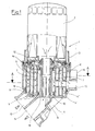
- the oil filter 1 consists of a filter housing 3 which receives a filter insert 2 and which is arranged on a filter base 4.
- the housing 3 surrounds the filter insert 2 only in its lower part, since in the exemplary embodiment a disposable Filter cartridge is inserted.
- the filter base 4 consists of two parts 4 'and 4 ", namely a cup part 4' (hatching increasing to the right) and an insert part 4" (hatching increasing to the left).
- the cup part 4 ' has a central drain channel 5 which runs in the direction of the longitudinal axis of the oil filter 1. This opens into the lower part of the base 4 in a line 14 which leads to a motor (not shown). Parallel to this is a second line 13 coming from the engine. Both lines 13 and 14 are used to guide engine oil.
- the insert part 4 is inserted against the cup part 4' by means of seals 18.
- the insert part 4" has four walls 9 parallel to one another and to the central drainage channel 5 in the example of the invention shown, thereby interacting with the cup part 4 'channels 6 and 7 are formed, the cross-sectional shape of which corresponds to that of a tall, narrow rectangle.
- the channels 7 are used to guide the oil that gets there through inlets 11 on the underside of the channels 7.
- the connection of the channels 7 to the filter housing 3 or the filter insert 2 located therein produce outlets 12 at the upper ends of the channels 7.
- the channels 6, which alternate with the channels 7 when viewed in the radial direction, serve to guide a coolant which is expediently cooling water from the engine cooling water circuit.
- the coolant channels 6 are closed by the underside of the filter housing 3, so that there are two completely separate circuits in which mixing of oil and coolant is excluded.
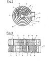
- FIG. 2 shows a section along the line AA in FIG.
- the central drainage channel 5 In the middle, the central drainage channel 5 can be seen, which has on its inside surface-enlarging ribs 10 'which run in the direction of the oil flow.
- the coolant passes through an inlet connector 15 on the outside of the base 3 into the channels 6, which are arranged concentrically with the outlet channel 5 at different distances.
- the channels 6 describe a reasonable 0 360 approaching bend and terminating at an outlet 16 for discharging the coolant, wherein the separation is effected from the inlet by a partition 17th
- two channels 7 are arranged for guiding the oil, these being divided into sections extending from one inlet 8 to the next inlet 8.
- the design of the channels 7 is particularly clear from the rolled-up representation of a part of a wall 9 of a channel 7 shown in FIG. 3.
- the channel 7 is divided into chamber-like channels 7 'and 7 ", arranged in two superimposed levels, the length of the Channels or chambers 7 'and 7 "is greater than their height.
- At one of the lower corners of the lower chambers 7 ' there is an inlet 11 through which oil flows into the chamber 7'.
- a passage 8 which in turn lies at the beginning of a chamber 7 "of the upper level.
- the upper chamber 7" in turn has an outlet 12 diagonally opposite the passage 8.
- ribs 10 on the walls 9 the heat exchanger area is increased and turbulence is generated in the flowing media.
- the height, number and spacing of the ribs 10 are at the discretion of the person skilled in the art and judge according to the requirements regarding heat exchange and pressure loss.
- An embodiment of the base without ribs or with ribs only in part of the channels is also conceivable.
- the engine oil to be filtered passes through line 13 coming from the engine into the base 4 of the oil filter. From there it is distributed through the inlets 11 into the chamber-like channels or chambers 7 '. After flowing through the chambers 7 'of the lower level in a circular direction, in the example clockwise, the transition into the chambers 7 "of the upper level follows through the passages 8. The chambers 7" are also flowed through by the oil in a circular direction in a clockwise direction and leave through outlets 12. Furthermore, the oil flows through the filter housing 3 and the filter insert 2 into the central drain channel 5 and from there through the line 14 back to the engine.
- coolant flows through the inlet port, i. a. Cooling water in the channels 6, this flows in a circular direction opposite to the oil, that is counterclockwise and exits through the outlet port 16 and is z. B. returned to the engine's cooling water circuit.
- a heat exchange takes place through the common walls 9 of the channels 6 and chambers 7 'and 7 ", the effectiveness of which is very high due to the fact that the media flowing past one another - coolant and oil - flow in countercurrent.
- the main purpose of the heat exchanger is to cool the with high temperature oil coming from the engine, but is also in the cold start phase the reverse effect is advantageous because the cooling water heats up faster than the engine oil.
- the already heated cooling water gives off heat to the oil, which improves its flow and lubricity in a desirable manner.
Landscapes
- Engineering & Computer Science (AREA)
- Mechanical Engineering (AREA)
- General Engineering & Computer Science (AREA)
- Physics & Mathematics (AREA)
- Thermal Sciences (AREA)
- Chemical & Material Sciences (AREA)
- Chemical Kinetics & Catalysis (AREA)
- Lubrication Details And Ventilation Of Internal Combustion Engines (AREA)
- Lubrication Of Internal Combustion Engines (AREA)
- Heat-Exchange Devices With Radiators And Conduit Assemblies (AREA)
Abstract
@ Ölfilter mit integriertem Wärmetauscher, insbesondere für Kraftfahrzeugmotoren, bestehend aus einem Filtereinsatz und einem den Einsatz aufnehmenden Filtergehäuse, das einen mit dem Motor verbundenen Sockel aufweist, und wobei das Öl an der Sockelunterseite vom Motor kommend randseitig in den Sockel einströmt und nach Durchströmen von Zulaufkanälen im Sockel und des Filtereinsatzes durch einen den Sockel in Längsrichtung durchsetzenden zentralen Ablaufkanal zum Motor abfließt, bei dem der Sockel (4) zusätzlich wenigstens einen Kanal (6) für die Führung eines Kühlmittels aufweist und die Kanäle (7) für das Öl und der Kanal/die Kanäle (6) für das Kühlmittel derart in wärmeleitendem Kontakt angeordnet sind, daß Öl und Kühlmittel weitgehend im Gegenstrom zueinander unter Wärmeaustausch fließen.
Description
Die Erfindung betrifft einen Ölfilter mit integriertem Wärmetauscher, insbesondere für Kraftfahrzeugmotoren, bestehend aus einem Filtereinsatz und einem den Einsatz aufnehmenden Filtergehäuse, das einen mit dem Motor verbundenen Sockel aufweist, und wobei das Öl an der Sockelunterseite vom Motor kommend randseitig in den Sockel einströmt und nach Durchströmen von Zulaufkanälen im Sockel und des Filtereinsatzes durch einen den Sockel in Längsrichtung durchsetzenden zentralen Ablaufkanal zum Motor abfließt.The invention relates to an oil filter with an integrated heat exchanger, in particular for motor vehicle engines, consisting of a filter insert and a filter housing which receives the insert and has a base connected to the engine, and the oil on the underside of the base flows into the base on the underside of the engine and after Flows through inlet channels in the base and the filter insert through a central outlet channel that passes through the base in the longitudinal direction and flows to the engine.
Aus der DE-OS 33 17 008 ist ein Filter mit integriertem Wärmetauscher bekannt. Bei diesem Filter erfolgt der Wärmetausch in dem den Filtereinsatz vollständig umgebenden Filtergehäuse. Hierzu ist im Gehäuse ein zusätzlicher, außenliegender Ringraum vorgesehen, der von einem Kühlmedium im wesentlichen im Querstrom zu dem zu filternden und zu kühlenden bzw. zu erwärmenden Medium durchströmt wird.From DE-OS 33 17 008 a filter with an integrated heat exchanger is known. With this filter, the heat exchange takes place in the filter housing completely surrounding the filter insert. For this purpose, an additional, external annular space is provided in the housing, through which a cooling medium flows essentially in cross flow to the medium to be filtered and cooled or heated.
Nachteilig bei diesem Filter ist, daß die Wärmeaustauschfläche relativ klein und damit der Wirkungsgrad gering ist und daß die Baugröße, hier vor allem der Durchmesser des Filtergehäuses, durch das Integrieren des Wärmetauschers erheblich vergrößert wird, was bei den häufig beengten Verhältnissen in Pkw-Motorräumen zu Problemen führt.The disadvantage of this filter is that the heat exchange area is relatively small and thus the efficiency is low and that the size, especially the diameter of the filter housing, is considerably increased by integrating the heat exchanger, which is due to the often cramped conditions in car engine rooms Leads to problems.
Es stellt sich daher die Aufgabe, einen Ölfilter der eingangs genannten Art zu schaffen, der die genannten Nachteile vermeidet und in dem ohne Zunahme der Baugröße ein Wärmeaustauscher mit hohem Wirkungsgrad integriert ist und der rationell und kostengünstig herstellbar ist.It is therefore the task of creating an oil filter of the type mentioned at the outset, which avoids the disadvantages mentioned and in which a heat exchanger with high efficiency is integrated without increasing the size and which can be produced economically and economically.
Die Lösung der Aufgabe gelingt erfindungsgemäß durch einen Ölfilter der eingangs genannten Art nach dem kennzeichnenden Teil des Anspruchs l.The object is achieved according to the invention by an oil filter of the type mentioned in the characterizing part of claim 1.
Durch die Integration des Wärmeaustauschers in den ohnehin vorhandenen Sockel des Filtergehäuses wird die Anforderung der Baugrößenminimierung in idealer Weise gelöst, während der hohe Wirkungsgrad des Wärmeaustauschers durch die Führung der beiden Medien im Gegenstrom erreicht wird.The integration of the heat exchanger in the already existing base of the filter housing ideally solves the requirement for minimizing the size, while the high efficiency of the heat exchanger is achieved by guiding the two media in counterflow.
Eine Ausgestaltung der Erfindung sieht die folgenden Merkmale vor:
- - wenigstens einen konzetrisch um den zentralen Ablaufkanal angeordnet, von dem Kühlmittel zirkular durchströmten Kanal und
- - durch zum Ablaufkanal konzentrisch wenigstens in einem Abstand in zwei Ebenen übereinander angeordnete, gegeneinander winkelversetzte und jeweils zu zweit übereinander durch einen Durchlaß in Verbindung stehende, in Gegenstromrichtung zum Kühlmittel öldurchströmte kammerartige Kanäle, deren Wandungen wenigstens teilweise zugleich die Wandungen des Kühlmittelkanals / der Kühlmittelkanäle bilden.
- - Arranged at least one concentrically around the central drain channel, through which the coolant flows and
- - Through chamber-like channels concentrically arranged at least at a distance in two planes one above the other, angularly offset from one another and in each case one above the other through a passage, through which oil flows in countercurrent direction to the coolant, the walls of which at least partially form the walls of the coolant channel / coolant channels .
Durch die konzentrische Anordnung der Kanäle wird eine optimale Raumausnutzung erreicht, die keinen toten Raum enthält. Die zirkulare Strömung des Kühlmittels wird dadurch erreicht, daß Kühlmitteleinlaß und -auslaß nahe benachbart diesseits bzw. jenseits einer radial verlaufenden Trennwand liegen, so daß das durchfließende Kühlmittel einen angenäherten 360 -Bogen beschreibt. Dies ergibt eine eindeutig definierte, einheitliche Strömungsrichtung des Kühlmediums im Wärmetauscher. Die eng benachbarte Lage von Kühlmitteleinlaß und -auslaß erlaubt eine platzsparende, parallele Führung der zugehörigen Leitungen bzw. Schläuche. Die Querschnittsform des Kühlmittelkanals ist vorzugsweise die eines hohen, schmalen Rechteckes, da so eine relativ große Wandungsfläche bei einem geringen radialen Platzbedarf erzielt wird.The concentric arrangement of the channels ensures optimal use of space that does not contain any dead space. The circular flow of coolant is achieved by having coolant inlet and outlet close lie adjacent to this or beyond a radially extending partition, so that the coolant flowing through describes an approximate 360 ° arc. This results in a clearly defined, uniform flow direction of the cooling medium in the heat exchanger. The closely adjacent position of the coolant inlet and outlet allows space-saving, parallel routing of the associated lines or hoses. The cross-sectional shape of the coolant channel is preferably that of a high, narrow rectangle, since a relatively large wall area is thus achieved with a small radial space requirement.
Um das zu filternde und zu kühlende Motoröl in den für einen guten Wirkungsgrad vorteilhaften Gegenstrom zum Kühlmittel zu bringen, ist die beschriebene Anordnung von kammerartigen Kanälen vorgesehen. Die Kammerquerschnittsform ähnelt der des Kühlmittelkanals, hat aber nur etwa deren halbe Höhe. Die zirkulare Erstreckung der Kammern ist so bemessen, daß diese die Höhe der Kammern deutlich übertrifft. Nach dem Einströmen in eine Kammer der unteren Ebene an deren einem Ende fließt also das Öl in zirkularer Richtung, d. h. der Haupterstreckungsrichtung der Kammer bis zum gegenüberliegenden Ende, steigt von dort durch einen Durchlaß in eine Kammer der oberen Ebene und verläßt diese an deren Ende nach oben und tritt in den Filtereinsatz ein. Je nach Höhe und Durchmesser des Filtersockels sowie Abstand der Kammern vom zentralen Kanal kann eine Anordnung mindestens je zwei Kammern pro Ebene umfassen, es kann aber auch eine größere Anzahl sein. Auch können in radialer Richtung gesehen mehrere Kammeranordnungen und Kühlmittelkanäle vorhanden sein.In order to bring the engine oil to be filtered and cooled in the counterflow to the coolant, which is advantageous for good efficiency, the arrangement of chamber-like channels described is provided. The chamber cross-sectional shape is similar to that of the coolant channel, but is only about half its height. The circular extent of the chambers is such that it clearly exceeds the height of the chambers. Thus, after flowing into a lower level chamber at one end, the oil flows in a circular direction, i. H. the main direction of extension of the chamber to the opposite end, rises from there through a passage into a chamber of the upper level and leaves this at its end upwards and enters the filter insert. Depending on the height and diameter of the filter base and the distance of the chambers from the central channel, an arrangement can comprise at least two chambers per level, but it can also be a larger number. A plurality of chamber arrangements and coolant channels can also be present in the radial direction.
Zu einer guten Wärmeübertragung trägt weiterhin bei, daß die Wandungen zum großen Teil auf einer Seite vom Öl und auf der anderen vom Kühlmittel überstrichen werden. Den Wärmeübergang behindernde Grenzflächen oder Zwischenräume sind nicht vorhanden.A good heat transfer also contributes to the fact that the walls are largely covered by oil on one side and the coolant on the other. The There are no interfaces or gaps that prevent heat transfer.
Der günstigste Strömungsverlauf des Öls ergibt sich in den Kammern, wenn die beiden miteinander verbundenen Kammern um einen solchen Winkel gegeneinander zirkular versetzt sind, daß die Überschneidung gerade noch die für den Durchlaß erforderliche Größe hat. Hierdurch wird das bestmögliche Verhältnis von zirkularem zu axialem Strömungsweg erreicht, so daß zwischen Öl und Kühlmittel weitgehend ein Gegenstrom besteht. Lediglich im Bereich von Kühlmitteleinlaß und -auslaß und zentralem Ablaufkanal ist dies nicht der Fall.The most favorable flow of the oil results in the chambers if the two interconnected chambers are offset circularly from one another by such an angle that the overlap is just the size required for the passage. As a result, the best possible ratio of circular to axial flow path is achieved, so that there is largely a counterflow between oil and coolant. This is not the case only in the area of the coolant inlet and outlet and the central drain channel.
Eine bevorzugte Ausführungsform des Ölfilters sieht vor, daß der Sockel drei konzentrische, parallel durchströmte Kanäle für das Kühlmittel und zwischen diesen zwei konzentrische Kammeranordnungen für das Öl aufweist. Hiermit wird einerseits eine genügend große Wärmeaustauschfläche erreicht, andererseits wird aber noch ein ausreichend großer Kanalquerschnitt gewährleistet, bei dem Druckverluste von Öl und Kühlmittel noch nicht zu hoch werden.A preferred embodiment of the oil filter provides that the base has three concentric, parallel flow channels for the coolant and between these two concentric chamber arrangements for the oil. On the one hand, this achieves a sufficiently large heat exchange area, but on the other hand, a sufficiently large duct cross section is still ensured, in which pressure losses of oil and coolant do not become too high.
Bei glattflächigen Wandungen der Kanäle stellt sich eine im wesentlichen laminare Strömung im Öl und im Kühlmittel ein, was einen Temperaturgradienten im fließenden Medium zur Folge hat. Hierbei erwärmen sich die wandungsnahen Schichten des Kühlmittels und die mittleren Schichten des Kühlmittels bleiben kühler. Umgekehrtes gilt für das Öl. Abhilfe schafft hier die Erzeugung von Turbulenzen, die eine gleichmäßigere Wärmeverteilung in den fließenden Medien und damit einen verstärkten Wärmeaustausch bewirken. Hierfür sind Rippen oder Vorsprünge auf den Wandungen der Kanäle und Kammern, bevorzugt auf den wärmeaustauschenden Wandungen, vorgesehen. Die Rippen erstrecken sich sinnvollerweise senkrecht zur Strömungsrichtung, d. h. parallel zum zentralen Ablaufkanal, um bestmöglich für eine Verwirbelung zu sorgen. Parallel wird die Wärmeaustauschfläche hierdurch weiter vergrößert.In the case of smooth-walled walls of the channels, an essentially laminar flow occurs in the oil and in the coolant, which results in a temperature gradient in the flowing medium. The layers of the coolant close to the wall heat up and the middle layers of the coolant remain cooler. The reverse applies to the oil. This is remedied by the generation of turbulence, which results in a more even heat distribution in the flowing media and thus an increased heat exchange. For this purpose, ribs or projections are provided on the walls of the channels and chambers, preferably on the heat-exchanging walls. The ribs sensibly extend perpendicular to the Flow direction, ie parallel to the central drainage channel, in order to ensure the best possible swirl. At the same time, the heat exchange area is further increased.
Weiterhin vorteilhaft ist es, wenn die Rippen abwechselnd auf einander gegenüberliegenden Wandungen eines Kanals angeordnet sind und eine Höhe haben, die etwa bis zur Mitte des Kanals reicht. Es wird so zusätzlich ein mäandrierender Fluß der Medien und so ein verlängerter Fließweg mit dem Ergebnis eines verbesserten Wärmeaustausches erzielt.It is also advantageous if the ribs are arranged alternately on opposite walls of a channel and have a height that extends approximately to the middle of the channel. In addition, a meandering flow of the media and thus an extended flow path are achieved with the result of an improved heat exchange.
Zur Verbesserung des Wärmeaustausches durch die Wandung des zentralen Ablaufkanals ist dieser vorteilhaft auf seiner Innenseite mit in Strömungsrichtung des Öls verlaufenden Rippen versehen. So wird die Wärmeaustauschfläche vergrößert, der Durchflußwiderstand aber nicht mehr nennenswert erhöht.In order to improve the heat exchange through the wall of the central drainage channel, it is advantageously provided on its inside with ribs running in the direction of flow of the oil. The heat exchange surface is increased, but the flow resistance is no longer significantly increased.
Um eine kostengünstige und rationelle Herstellung zu gewährleisten, ist vorgesehen, daß der Sockel aus zwei ineinandergesetzten, gegeneinander abgedichteten Teilen besteht, nämlich aus einem Becherteil mit dem zentralen Ablaufkanal und einem Einsatzteil. Der Einsatzteil umfaßt zumindest eine ringförmige Kammeranordnung, kann aber auch zwei oder mehr derartiger Anordnungen aufweisen. Die Abdichtung der beiden Teile gegeneinander kann beispielsweise durch O-Ringe oder auch durch Verklebung erfolgen. Nach oben werden die ineinandergesteckten Teile durch das den Filtereinsatz aufnehmende Gehäuse abgedeckt bzw. verschlossen. Durch die beschriebene Konstruktion des Sockels in zwei Teilen wird der Montageaufwand bei der Herstellung sehr gering.In order to ensure cost-effective and efficient production, it is provided that the base consists of two nested parts that are sealed against one another, namely a cup part with the central drainage channel and an insert part. The insert part comprises at least one annular chamber arrangement, but can also have two or more such arrangements. The two parts can be sealed off from one another, for example by O-rings or by gluing. The nested parts are covered or closed at the top by the housing receiving the filter insert. Due to the described construction of the base in two parts, the assembly effort during manufacture is very low.
Besonders vorteilhaft ist es, zumindest die wärmeaustauschenden Wandungen aus Aluminium herzustellen. Aluminium hat sowohl eine gute Wärmeleitfähigkeit als auch ein geringes Gewicht und läßt sich sehr leicht bearbeiten.It is particularly advantageous to produce at least the heat-exchanging walls from aluminum. aluminum has both good thermal conductivity and low weight and is very easy to machine.
Besondere wirtschaftliche Vorteile ergeben sich daraus, daß vorgesehen ist, zumindest den Becherteil und den Einsatzteil im Druckgußverfahren herzustellen. Dies ist bei der beschriebenen Ausführung der Sockelteile problemlos möglich, da die Voraussetzung der Entformbarkeit, d. h. die Möglichkeit, Gußformen nach dem Gießen von dem Gußteil einfach zu trennen, gegeben ist. Nach dem Guß ist lediglich eine Bearbeitung von geringem Umfang erforderlich.Particular economic advantages result from the fact that provision is made for at least the cup part and the insert part to be produced by the die-casting process. This is easily possible with the described design of the base parts, since the requirement of demoldability, i. H. it is possible to easily separate molds from the casting after casting. After casting, only a small amount of machining is required.
Der erfindungsgemäße Ölfilter mit integriertem Wärmeaustauscher ist damit im Vergleich zu bekannten derartigen Ölfiltern sowohl rationeller und kostengünstiger herstellbar als auch wirkungsvoller.The oil filter according to the invention with an integrated heat exchanger is therefore both more efficient and less expensive to produce and more effective than known oil filters of this type.
Eine bevorzugte Ausführungsform der Erfindung wird im folgenden anhand einer Zeichnung näher beschrieben. Es zeigen im einzelnen:
- Figur 1 einen erfindungsgemäßen Ölfilter in Vertikalschnitt,
Figur 2 einen Filtersockel des erfindungsgemäßen Ölfilters im Horizontalschnitt entlang der Linie A - A in Figur 1 undFigur 3 eine Anordnung von kammerartigen Kanälen im Filtersockel in abgerollter Darstellung.
- FIG. 1 shows an oil filter according to the invention in vertical section,
- Figure 2 shows a filter base of the oil filter according to the invention in horizontal section along the line A - A in Figure 1 and
- Figure 3 shows an arrangement of chamber-like channels in the filter base in a rolled representation.
Wie Figur 1 zeigt, besteht der erfindungsgemäße Ölfilter 1 aus einem einen Filtereinsatz 2 aufnehmenden Filtergehäuse 3, das auf einem Filtersockel 4 angeordnet ist. Das Gehäuse 3 umgibt den Filtereinsatz 2 nur in seinem unteren Teil, da im Ausführungsbeispiel eine Wegwerf-Filterpatrone eingesetzt ist.As FIG. 1 shows, the oil filter 1 according to the invention consists of a
Der Filtersockel 4 besteht aus zwei Teilen 4' und 4", nämlich einem Becherteil 4' (Schraffur nach rechts steigend) und einem Einsatzteil 4" (Schraffur nach links steigend). In seiner Mitte weist der Becherteil 4' einen zentralen, in Richtung der Längsachse des Ölfilters 1 verlaufenden Ablaufkanal 5 auf. Dieser mündet im unteren Teil des Sockels 4 in eine Leitung 14, die zu einem Motor (nicht dargestellt) führt. Parallel hierzu verläuft eine zweite, vom Motor kommende Leitung 13. Beide Leitungen 13 und 14 dienen zur Führung von Motoröl.The
In den Becherteil 4' ist der Einsatzteil 4" unter Abdichtung mittels Dichtungen 18 gegen den Becherteil 4' eingesetzt. Der Einsatzteil 4" weist im dargestellten Beispiel der Erfindung vier zueinander und zum zentralen Ablaufkanal 5 parallele Wandungen 9 auf, wodurch im Zusammenwirken mit dem Becherteil 4' Kanäle 6 und 7 gebildet werden, deren Querschnittsform der eines hohen schmalen Rechteckes entspricht. Die Kanäle 7 dienen der Führung des Öls, das durch Einlässe 11 an der Unterseite der Kanäle 7 dorthin gelangt. Die Verbindung der Kanäle 7 mit dem Filtergehäuse 3 bzw. dem darin befindlichen Filtereinsatz 2 stellen Auslässe 12 an den oberen Enden der Kanäle 7 her. Die Kanäle 6, die sich in radialer Richtung gesehen mit den Kanälen 7 abwechseln, dienen der Führung eines Kühlmittels, das zweckmäßig Kühlwasser aus dem Motorkühlwasserkreislauf ist. Nach oben sind die Kühlmittelkanäle 6 durch die Unterseite des Filtergehäuses 3 verschlossen, so daß zwei völlig getrennte Kreisläufe gegeben sind, bei denen eine Vermischung von Öl und Kühlmittel ausgeschlossen ist.In the cup part 4 ', the
Die wechselweise Anordnung der Kanäle 6 und 7 für Kühlmittel und Öl zeigt besonders deutlich Figur 2, die einen Schnitt entlang der Linie A - A in Figur 1 zeigt.The alternate arrangement of the
In der Mitte ist der zentrale Ablaufkanal 5 zu erkennen, der auf seiner Innenseite oberflächenvergrößernde Rippen 10' aufweist, die in Richtung der Ölströmung verlaufen. Das Kühlmittel gelangt durch einen Einlaufstutzen 15 an der Außenseite des Sockels 3 in die Kanäle 6, die mit unterschiedlichen Abständen konzentrisch zum Ablaufkanal 5 angeordnet sind. Die Kanäle 6 beschreiben einen ange- 0 näherten 360 -Bogen und enden an einem Auslaßstutzen 16 zum Abführen des Kühlmittels, wobei die Trennung vom Einlaß durch eine Trennwand 17 erfolgt. Zwischen den drei Kühlmittelkanälen 6 sind zwei Kanäle 7 zur Führung des Öls angeordnet, wobei diese in von einem Einlaß 8 bis zum nächsten Einlaß 8 sich erstreckende Teilabschnitte unterteilt sind.In the middle, the
Die Gestaltung der Kanäle 7 wird besonders deutlich aus der in Figur 3 gezeigten abgerollten Darstellung eines Teiles einer Wandung 9 eines Kanals 7. Der Kanal 7 ist in kammerartige Kanäle 7' und 7", angeordnet in zwei übereinanderliegenden Ebenen, unterteilt, wobei die Längenerstreckung der Kanäle bzw. Kammern 7' und 7" größer ist als deren Höhe. An einer der unteren Ecken der unteren Kammern 7' ist jeweils ein Einlaß 11 angeordnet, durch den Öl in die Kammer 7' einströmt. An der diagonal gegenüberliegenden Ecke ist ein Durchlaß 8 vorhanden, der seinerseits am Anfang einer Kammer 7" der oberen Ebene liegt. Die obere Kammer 7" verfügt wiederum diagonal gegenüber dem Durchlaß 8 über einen Auslaß 12. Diese Anordnung von je zwei versetzt übereinander angeordneten Kammern 7' und 7" wiederholt sich je nach dem verfügbaren Raum, abhängig vom Abstand vom zentralen Ablaufkanal 5, ein- bis mehrmal.The design of the
Durch Rippen 10 auf den Wandungen 9 wird die Wärmetauscherfläche vergrößert und es werden Turbulenzen in den fließenden Medien erzeugt. Höhe, Anzahl und Abstand der Rippen 10 liegen im Ermessen des Fachmannes und richten sich nach den Erfordernissen bezüglich Wärmeaustausch und Druckverlust. Auch eine Ausführung des Sockels ohne Rippen oder mit Rippen nur in einem Teil der Kanäle ist denkbar.By
Schließlich wird im folgenden noch kurz die Funktionsweise des erfindungsgemäßen Ölfilters mit integriertem Wärmeaustauscher erläutert.Finally, the mode of operation of the oil filter according to the invention with an integrated heat exchanger is briefly explained below.
Das zu filternde Motoröl gelangt durch die Leitung 13 vom Motor kommend in den Sockel 4 des Ölfilters. Von dort wird es durch die Einlässe 11 in die kammerartigen Kanäle bzw. Kammern 7' verteilt. Nach dem Durchströmen der Kammern 7' der unteren Ebene in zirkularer Richtung, im Beispiel mit dem Uhrzeigersinn, folgt der Übergang in die Kammern 7" der oberenen Ebene durch die Durchlässe 8. Die Kammern 7" werden ebenfalls in zirkularer Richtung im Uhrzeigersinn vom Öl durchströmt und durch Auslässe 12 verlassen. Weiter fließt das Öl durch das Filtergehäuse 3 und den Filtereinsatz 2 in den zentralen Ablaufkanal 5 und von dort durch die Leitung 14 zurück zum Motor.The engine oil to be filtered passes through
Parallel hierzu strömt durch den Einlaßstutzen 15 Kühlmittel, i. a. Kühlwasser in die Kanäle 6 ein, durchfließt diese in zirkularer Richtung entgegengesetzt zum Öl, also gegen den Uhrzeigersinn und tritt durch den Auslaßstutzen 16 wieder aus und wird z. B. in den Kühlwasserkreislauf des Motors zurückgeführt.In parallel, 15 coolant flows through the inlet port, i. a. Cooling water in the
Durch die gemeinsamen Wandungen 9 der Kanäle 6 und Kammern 7' und 7" findet ein Wärmeaustausch statt, dessen Effektivität dadurch, daß die aneinander vorbeifließenden Medien - Kühlmittel und Öl - im Gegenstrom fließen, sehr hoch ist. Der Hauptzweck des Wärmeaustauschers ist die Kühlung des mit hoher Temperatur vom Motor kommenden Öls. In der Kaltstartphase ist aber auch der umgekehrte Effekt vorteilhaft, denn das Kühlwasser erwärmt sich schneller als das Motoröl. Somit gibt in der Kaltstartphase das schon erwärmte Kühlwasser Wärme an das Öl ab, wodurch dessen Fließ- und Schmierfähigkeit in wünschenswerter Weise verbessert wird.A heat exchange takes place through the
Claims (9)
dadurch gekennzeichnet, daß der Sockel (4) zusätzlich wenigstens einen Kanal (6) für die Führung eines Kühlmittels aufweist und daß die Kanäle (7) für das Öl und der Kanal/die Kanäle (6) für das Kühlmittel derart in wärmeleitendem Kontakt angeordnet sind, daß Öl und Kühlmittel weitgehend im Gegenstrom zueinander unter Wärmeaustausch fließen.1. Oil filter with an integrated heat exchanger, in particular for motor vehicle engines, consisting of a filter insert and a filter housing that receives the insert, which has a base connected to the engine, and where the oil on the underside of the base flows into the base on the underside of the engine and after it flows through Inlet channels in the base and the filter insert flow to the engine through a central outlet channel that extends through the base in the longitudinal direction,
characterized in that the base (4) additionally has at least one channel (6) for guiding a coolant and in that the channels (7) for the oil and the channel (s) (6) for the coolant are arranged in such a way in heat-conducting contact that oil and coolant flow largely in countercurrent to each other with heat exchange.
durch zum AblaufkanaJ (5) konzentrisch wenigstens in einem Abstand in zwei Ebenen übereinander angeordnete, gegeneinander winkelversetzte und jeweils zu zweit übereinander durch einen Durchlaß (8) in Verbindung stehende, in Gegenstromrichtung zum Kühlmittel öldurchströmte, kammerartige Kanäle (7', 7"), deren Wandungen (9) wenigstens teilweise zugleich die Wandungen (9) des Kühlmittelkanals / der Kühlmittelkanäle (6) bilden.2. Oil filter according to claim 1, characterized by at least one concentrically arranged around the central drain channel (5), circularly flowed through by the coolant channel (6) and
through chamber-like channels (7 ', 7 ") concentrically arranged at least at a distance from one another in two planes, offset at an angle to one another and each one above the other through a passage (8) and through which oil flows in the countercurrent direction to the coolant, the walls (9) of which at least partially form the walls (9) of the coolant channel (s) (6).
Applications Claiming Priority (2)
| Application Number | Priority Date | Filing Date | Title |
|---|---|---|---|
| DE3508834 | 1985-03-13 | ||
| DE19853508834 DE3508834A1 (en) | 1985-03-13 | 1985-03-13 | OIL FILTER WITH INTEGRATED HEAT EXCHANGER |
Publications (2)
| Publication Number | Publication Date |
|---|---|
| EP0200809A2 true EP0200809A2 (en) | 1986-11-12 |
| EP0200809A3 EP0200809A3 (en) | 1987-10-07 |
Family
ID=6264971
Family Applications (1)
| Application Number | Title | Priority Date | Filing Date |
|---|---|---|---|
| EP85106783A Withdrawn EP0200809A3 (en) | 1985-03-13 | 1985-06-01 | Oil filter having a heat exchanger integrated therein |
Country Status (2)
| Country | Link |
|---|---|
| EP (1) | EP0200809A3 (en) |
| DE (1) | DE3508834A1 (en) |
Cited By (13)
| Publication number | Priority date | Publication date | Assignee | Title |
|---|---|---|---|---|
| WO1992009794A1 (en) * | 1990-12-03 | 1992-06-11 | Allied-Signal Inc. | Modular lubrication/filter system |
| DE4242831C1 (en) * | 1992-12-18 | 1994-03-10 | Goetze Ag | Oil cooler for IC engines - has anchoring elements in oil intake/discharge apertures, to connect sealing plate and insert |
| EP0622600A1 (en) * | 1993-04-24 | 1994-11-02 | Knecht Filterwerke Gmbh | Flat plate oil cooler assembly |
| EP0631804A1 (en) * | 1993-07-02 | 1995-01-04 | Filtrauto | Oil filter with cooling device |
| DE19544088A1 (en) * | 1995-11-27 | 1997-05-28 | Knecht Filterwerke Gmbh | Liquid filter with a stacked disc heat exchanger |
| EP0800850A1 (en) * | 1996-04-10 | 1997-10-15 | Filtrauto | Oil filtering and cooling device |
| EP0748646A3 (en) * | 1995-06-16 | 1998-02-25 | Ing. Walter Hengst GmbH & Co. KG | Liquid filter |
| WO1998010176A1 (en) * | 1996-09-04 | 1998-03-12 | Filterwerk Mann + Hummel Gmbh | Subassembly for an internal combustion engine |
| DE19701066A1 (en) * | 1997-01-15 | 1998-07-16 | Mann & Hummel Filter | Device for filtering oil |
| EP0874140A1 (en) * | 1997-04-23 | 1998-10-28 | Längerer & Reich GmbH | Cooler and filter apparatus |
| US5975245A (en) * | 1995-02-18 | 1999-11-02 | The Glacier Metal Company Limited | Temperature regulating liquid conditioning arrangement |
| CN104329157A (en) * | 2014-09-04 | 2015-02-04 | 浙江环球滤清器有限公司 | Integrated engine oil lubricating module system and engine oil filtering lubricating method thereof |
| CN115977763A (en) * | 2022-12-21 | 2023-04-18 | 江门市大长江集团有限公司 | Engine oil cooler, engine assembly and motorcycle |
Families Citing this family (2)
| Publication number | Priority date | Publication date | Assignee | Title |
|---|---|---|---|---|
| DE3605825C1 (en) * | 1986-02-22 | 1987-08-20 | Hengst Walter Gmbh & Co Kg | Heat exchanger for two fluid media |
| DE9309741U1 (en) * | 1993-06-30 | 1993-08-26 | Filterwerk Mann & Hummel Gmbh, 71638 Ludwigsburg | Heat exchanger |
Family Cites Families (6)
| Publication number | Priority date | Publication date | Assignee | Title |
|---|---|---|---|---|
| US1723741A (en) * | 1929-08-06 | manning | ||
| DE1934193C3 (en) * | 1969-07-05 | 1979-04-26 | Farymann - Diesel Farny & Weidmann Gmbh & Co Kg, 6840 Lampertheim | Oil cooler training and fastening together with an oil filter in the water-cooled lubricating oil circuit of an internal combustion engine |
| DE2845520C2 (en) * | 1978-10-19 | 1987-03-26 | Robert Bosch Gmbh, 7000 Stuttgart | Screw-on filter unit for liquids, especially diesel fuel |
| DE3317008C2 (en) * | 1983-05-10 | 1985-04-04 | Knecht Filterwerke Gmbh, 7000 Stuttgart | Filter housing with integrated heat exchanger |
| JPS6144294A (en) * | 1984-08-07 | 1986-03-03 | Nippon Denso Co Ltd | Heat exchanger |
| DE3444267C3 (en) * | 1984-12-05 | 1993-12-02 | Hengst Walter Gmbh & Co Kg | Liquid filter |
-
1985
- 1985-03-13 DE DE19853508834 patent/DE3508834A1/en not_active Ceased
- 1985-06-01 EP EP85106783A patent/EP0200809A3/en not_active Withdrawn
Cited By (17)
| Publication number | Priority date | Publication date | Assignee | Title |
|---|---|---|---|---|
| WO1992009794A1 (en) * | 1990-12-03 | 1992-06-11 | Allied-Signal Inc. | Modular lubrication/filter system |
| DE4242831C1 (en) * | 1992-12-18 | 1994-03-10 | Goetze Ag | Oil cooler for IC engines - has anchoring elements in oil intake/discharge apertures, to connect sealing plate and insert |
| EP0622600A1 (en) * | 1993-04-24 | 1994-11-02 | Knecht Filterwerke Gmbh | Flat plate oil cooler assembly |
| EP0631804A1 (en) * | 1993-07-02 | 1995-01-04 | Filtrauto | Oil filter with cooling device |
| FR2707519A1 (en) * | 1993-07-02 | 1995-01-20 | Labinal | Oil filter associated with a cooling device. |
| US5975245A (en) * | 1995-02-18 | 1999-11-02 | The Glacier Metal Company Limited | Temperature regulating liquid conditioning arrangement |
| EP0748646A3 (en) * | 1995-06-16 | 1998-02-25 | Ing. Walter Hengst GmbH & Co. KG | Liquid filter |
| DE19544088A1 (en) * | 1995-11-27 | 1997-05-28 | Knecht Filterwerke Gmbh | Liquid filter with a stacked disc heat exchanger |
| FR2747318A1 (en) * | 1996-04-10 | 1997-10-17 | Filtrauto | OIL FILTERING AND COOLING DEVICE |
| EP0800850A1 (en) * | 1996-04-10 | 1997-10-15 | Filtrauto | Oil filtering and cooling device |
| WO1998010176A1 (en) * | 1996-09-04 | 1998-03-12 | Filterwerk Mann + Hummel Gmbh | Subassembly for an internal combustion engine |
| DE19701066A1 (en) * | 1997-01-15 | 1998-07-16 | Mann & Hummel Filter | Device for filtering oil |
| WO1998031449A1 (en) * | 1997-01-15 | 1998-07-23 | Filterwerk Mann + Hummel Gmbh | Oil-filtering device |
| DE19701066B4 (en) * | 1997-01-15 | 2016-12-15 | Mann + Hummel Gmbh | Device for filtering oil |
| EP0874140A1 (en) * | 1997-04-23 | 1998-10-28 | Längerer & Reich GmbH | Cooler and filter apparatus |
| CN104329157A (en) * | 2014-09-04 | 2015-02-04 | 浙江环球滤清器有限公司 | Integrated engine oil lubricating module system and engine oil filtering lubricating method thereof |
| CN115977763A (en) * | 2022-12-21 | 2023-04-18 | 江门市大长江集团有限公司 | Engine oil cooler, engine assembly and motorcycle |
Also Published As
| Publication number | Publication date |
|---|---|
| EP0200809A3 (en) | 1987-10-07 |
| DE3508834A1 (en) | 1986-09-25 |
Similar Documents
| Publication | Publication Date | Title |
|---|---|---|
| DE69004220T2 (en) | Heat exchanger with a circumferential circulation. | |
| DE69414474T2 (en) | Heat exchanger with an integrated filter | |
| DE69216389T2 (en) | OFFSET STRIP-SHAPED RIB FOR A COMPACT HEAT EXCHANGER | |
| EP1682840B1 (en) | Heat exchanger in particular for motor vehicles | |
| EP0200809A2 (en) | Oil filter having a heat exchanger integrated therein | |
| DE3017701A1 (en) | HEAT EXCHANGER FOR MULTIPLE FLUIDS | |
| DE1937122C3 (en) | Tubular heat transfer device | |
| EP0180086B1 (en) | Oil cooler | |
| EP2798297A1 (en) | Kit for heat exchanger, a heat exchanger core, and a heat exchanger | |
| DE3513936C2 (en) | Cooling device for a multi-stage compressor | |
| EP0286704B1 (en) | Heat exchanger for two fluid media | |
| DE4327213C2 (en) | Recuperative heat exchangers, in particular coolers for motor vehicles | |
| DE69700220T2 (en) | Method for producing a distribution device for evenly distributing the medium in a plurality of heat exchanger tubes | |
| DE2111387A1 (en) | Multipass tube heat exchanger - with variable numbers of passes for both fluids | |
| DE3209760C2 (en) | Heat exchanger | |
| DE2306426A1 (en) | HEAT EXCHANGER | |
| EP0386131B1 (en) | Countercurrent heat-exchanger | |
| DE10049890B4 (en) | Stacked-plate heat exchanger | |
| DE2216586A1 (en) | CIRCULATING HEAT EXCHANGER | |
| DE830804C (en) | Heat exchanger | |
| EP2049859B1 (en) | Motor vehicle air conditioning system | |
| EP0197169B1 (en) | Oil cooler | |
| DE807939C (en) | Heat exchanger | |
| AT411624B (en) | PLATE HEAT EXCHANGERS, ESPECIALLY OIL COOLERS | |
| DE3510441A1 (en) | Heat exchanger, in particular for two liquid media |
Legal Events
| Date | Code | Title | Description |
|---|---|---|---|
| PUAI | Public reference made under article 153(3) epc to a published international application that has entered the european phase |
Free format text: ORIGINAL CODE: 0009012 |
|
| AK | Designated contracting states |
Kind code of ref document: A2 Designated state(s): AT BE CH DE FR GB IT LI LU NL SE |
|
| PUAL | Search report despatched |
Free format text: ORIGINAL CODE: 0009013 |
|
| AK | Designated contracting states |
Kind code of ref document: A3 Designated state(s): AT BE CH DE FR GB IT LI LU NL SE |
|
| STAA | Information on the status of an ep patent application or granted ep patent |
Free format text: STATUS: THE APPLICATION IS DEEMED TO BE WITHDRAWN |
|
| 18D | Application deemed to be withdrawn |
Effective date: 19870701 |
|
| RIN1 | Information on inventor provided before grant (corrected) |
Inventor name: BAUMANN, DIETER, DIPL.-ING. |