EP0200753B1 - Erosion-protecting surface covering for laying out on earth surfaces exposed to water - Google Patents
Erosion-protecting surface covering for laying out on earth surfaces exposed to water Download PDFInfo
- Publication number
- EP0200753B1 EP0200753B1 EP19850905321 EP85905321A EP0200753B1 EP 0200753 B1 EP0200753 B1 EP 0200753B1 EP 19850905321 EP19850905321 EP 19850905321 EP 85905321 A EP85905321 A EP 85905321A EP 0200753 B1 EP0200753 B1 EP 0200753B1
- Authority
- EP
- European Patent Office
- Prior art keywords
- erosion
- surface covering
- mat
- protecting surface
- blocks
- Prior art date
- Legal status (The legal status is an assumption and is not a legal conclusion. Google has not performed a legal analysis and makes no representation as to the accuracy of the status listed.)
- Expired
Links
Images

Classifications
-
- E—FIXED CONSTRUCTIONS
- E02—HYDRAULIC ENGINEERING; FOUNDATIONS; SOIL SHIFTING
- E02B—HYDRAULIC ENGINEERING
- E02B3/00—Engineering works in connection with control or use of streams, rivers, coasts, or other marine sites; Sealings or joints for engineering works in general
- E02B3/04—Structures or apparatus for, or methods of, protecting banks, coasts, or harbours
- E02B3/12—Revetment of banks, dams, watercourses, or the like, e.g. the sea-floor
- E02B3/122—Flexible prefabricated covering elements, e.g. mats, strips
- E02B3/123—Flexible prefabricated covering elements, e.g. mats, strips mainly consisting of stone, concrete or similar stony material
Definitions
- the invention relates to an erosion-protecting surface covering for laying out on the sea bed, coastal areas and other earth surfaces which are exposed to water, said covering comprising a mat with concrete blocks resting on the top side.
- a covering is known, for example, from FR-A-2 411 269.
- Erosion can arise during storms and floods, while harbours are exposed to a bottom erosion which occurs particularly in sailing channels, and at ferry ports where the ferries are so large that the propellers are only a few metres above the sea bed.
- the providing of a resilient bush in at least the hole in the upper block prevents the formation of cracks and destruction of the blocks by powerful influence from the bolts by dimensional changes, frost and the like.
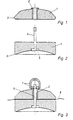
- FIG. 1 a preferred embodiment of the covering according to the invention. It is built up of hexagon-shaped concrete blocks, as shown in flg. 4, which shows the upper block 1 seen from above, mounted on a mat 8.
- the blocks comprise an upper block 1, which is shown in fig. 1, and a lower block 4, which is shown in fig. 2.
- the blocks 1, 4 have plane upper and lower sides respectively, so that they can lie up against the flexible loom in the form of the mat 8.
- the blocks 1 and 4 there are holes through which a bolt 6 with a bent-over head can be inserted with the bent head in a countersinking 5 in the bottom of the lower block 4.
- the upper block 1 is provided with an elastic bush 2 of synthetic material or rubber for the absorption of possible stresses. As will appear from fig. 3, the parts are tightened together around the mat 8 by means of an eyebolt 7.
- the underside of the lower block 4 is also made concave, and it can suck itself firmly to the bottom after the laying out. Furthermore, the upper block 1 is tapered upwards in order to reduce the resistance to current.
- the blocks are made by being moulded in concrete, and can have a breadth of about 50 cm and thickness of about 15 cm.
- the blocks 1 and 4 are rounded off 3 on the undersides along the side edges in order to make them more resistant to external influences.
- staggered rows of blocks are secured to the mat, which can be of synthetic fibres or the like.
- the mat can have a breadth of about 2.5 m and a length of about 6 m.
- Such an assembled covering will have a weight of about 6,000 kg.
- the laying out can be effected by suspension in a lifting arrangement comprising a yoke 10 with lifting lines 11 and a lifting cable 12 for a crane.
- the mats 8a and 8b can be positioned in such way that they overlap each other, after which a diver can bore holes through the mats and place concrete blocks under and over the mats respectively as shown in the drawing.
Landscapes
- Engineering & Computer Science (AREA)
- General Engineering & Computer Science (AREA)
- Environmental & Geological Engineering (AREA)
- Ocean & Marine Engineering (AREA)
- Mechanical Engineering (AREA)
- Civil Engineering (AREA)
- Structural Engineering (AREA)
- Revetment (AREA)
Abstract
Description
- The invention relates to an erosion-protecting surface covering for laying out on the sea bed, coastal areas and other earth surfaces which are exposed to water, said covering comprising a mat with concrete blocks resting on the top side. Such a covering is known, for example, from FR-A-2 411 269.
- Erosion can arise during storms and floods, while harbours are exposed to a bottom erosion which occurs particularly in sailing channels, and at ferry ports where the ferries are so large that the propellers are only a few metres above the sea bed.
- When the ships execute the necessary man- aeuvres, the propellers frequently flush sand away from the bottom and from the area near the piling walls, so that the lower ends of the piles are more or less exposed, and thus there is danger of collapse of the quay and its approaches.
- In order to moderate the effects of the current from the propellers, it is known to lay mats on the sea bed, self-locking slabs, gabions or the like. The mats are secured by large sea-stones of up to 3 tonnes with eyebolts inserted, which are held together by heavy iron chains through these eyebolts.
- However, when such a securing of a strongly- influenced bottom area has taken place, there occurs a violent erosion of the non-secured sea bed along the edges of the mats, whereby the large sea-stones can come to hang freely in their chains over the sea bed, with the risk of the mats being ruined, and thereby the securing of the bottom.
- The use of mutually interlocking concrete slabs demands a levelling of the sea bed and a securing of the outer edge area of the concrete slabs, which can be effected by means of large gabions which are buried down in the bottom. These slabs must be controlled and firmly locked by divers. This is an extremely difficult and time-consuming procedure, and in the event of an eventual break in the slabs, repair operations are very difficult and expensive to carry out.
- It is also known to lay out a membrane made of synthetic material, steel mesh or asphalt to which concrete elements are affixed or secured. However, this is an expensive and complicated laying- out procedure, in that the construction of. this securing arrangement demands that it be layed out in one continuous course.
- It is the object of the invention to remedy these deficiences in the known surface coverings, and at the same time to improve and reduce the cost of bottom securing, and also to make it possible for eventual repairs to be carried out in a good and convenient manner for the divers.
- This is achieved by a surface covering where on the underside of the mat, opposite each of the concrete blocks resting on it, there is mounted a further concrete block in such a manner that the mat is clamped between the pairs of opposite-facing concrete blocks. There is thus achieved a protection covering which can remain on the bottom, in that it can normally be laid down completely without levelling of the bottom, with possibility of adapting of the weight of the elements in accordance with the current conditions and the type of bottom. The mat functions as a protection layer against erosion brought about by water currents from above, and gradually it will become an integral part of the sea bottom, the reason being that earth, sand and the like will be deposited under the mat, so that it will finally become embedded in the bottom.
- As presented in
claim 2, by bolting the concrete blocks together around the mat, the possibility is achieved of constructing the covering in modules on land, and by means of lifting cables through the eyes, the covering can be lowered down into place, where a diver can then assemble adjacent modules in a safe and simple manner. - As presented in
claim 3, the providing of a resilient bush in at least the hole in the upper block prevents the formation of cracks and destruction of the blocks by powerful influence from the bolts by dimensional changes, frost and the like. - As presented in claim 4, by providing the concrete blocks with plane assembly surfaces, the greatest possible degree of protection is achieved for the mat and the blocks.
- As presented in claim 5, by providing the lower blocks with a hollowed-out bottom, these can suck themselves firmly to the sea bed, and by making the upper blocks tapered, the surface of attack is smaller and therefore less exposed to the influences of the current.
- Finally, as presented in
claim 6, it is expedient to provide the blocks with a hexagon form, in that they will then be able to be placed at the same mutual intervals in staggered rows on the mat. - The invention will now be described in closer detail with reference to the drawing, where
- fig. 1 shows a cross-section of the upper concrete block,
- fig. 2 shows a cross-section of the lower concrete block,
- fig. 3 shows a cross-section of the blocks bolted together on a mat,
- fig. 4 shows the covering from above,
- fig. 5 shows the covering with lifting arrangement,. and
- fig. 6 shows the assembly of adjacent covering modules.
- In the drawing is shown a preferred embodiment of the covering according to the invention. It is built up of hexagon-shaped concrete blocks, as shown in flg. 4, which shows the
upper block 1 seen from above, mounted on amat 8. - The blocks comprise an
upper block 1, which is shown in fig. 1, and a lower block 4, which is shown in fig. 2. - The
blocks 1, 4 have plane upper and lower sides respectively, so that they can lie up against the flexible loom in the form of themat 8. - Through the
blocks 1 and 4 there are holes through which abolt 6 with a bent-over head can be inserted with the bent head in a countersinking 5 in the bottom of the lower block 4. Theupper block 1 is provided with anelastic bush 2 of synthetic material or rubber for the absorption of possible stresses. As will appear from fig. 3, the parts are tightened together around themat 8 by means of aneyebolt 7. - The underside of the lower block 4 is also made concave, and it can suck itself firmly to the bottom after the laying out. Furthermore, the
upper block 1 is tapered upwards in order to reduce the resistance to current. - Preferably, the blocks are made by being moulded in concrete, and can have a breadth of about 50 cm and thickness of about 15 cm. Moreover, the
blocks 1 and 4 are rounded off 3 on the undersides along the side edges in order to make them more resistant to external influences. - As will appear from fig. 4, staggered rows of blocks are secured to the mat, which can be of synthetic fibres or the like. The mat can have a breadth of about 2.5 m and a length of about 6 m. Such an assembled covering will have a weight of about 6,000 kg.
- As shown in fig. 5, the laying out can be effected by suspension in a lifting arrangement comprising a
yoke 10 withlifting lines 11 and alifting cable 12 for a crane. - When the covering is placed on the sea bottom, as shown in fig. 6, the
mats - In this way, a coherent covering can be built up on the sea bed, and this can be effected in a hitherto unknown simple and effective manner.
Claims (6)
Applications Claiming Priority (2)
| Application Number | Priority Date | Filing Date | Title |
|---|---|---|---|
| DK5028/84 | 1984-10-22 | ||
| DK502884A DK153897C (en) | 1984-10-22 | 1984-10-22 | EROSION PROTECTIVE COATING FOR WATER-SURFACING SURFACES |
Publications (2)
| Publication Number | Publication Date |
|---|---|
| EP0200753A1 EP0200753A1 (en) | 1986-11-12 |
| EP0200753B1 true EP0200753B1 (en) | 1989-02-22 |
Family
ID=8138797
Family Applications (1)
| Application Number | Title | Priority Date | Filing Date |
|---|---|---|---|
| EP19850905321 Expired EP0200753B1 (en) | 1984-10-22 | 1985-10-22 | Erosion-protecting surface covering for laying out on earth surfaces exposed to water |
Country Status (5)
| Country | Link |
|---|---|
| EP (1) | EP0200753B1 (en) |
| AU (1) | AU4867885A (en) |
| DE (1) | DE3568360D1 (en) |
| DK (1) | DK153897C (en) |
| WO (1) | WO1986002680A1 (en) |
Families Citing this family (2)
| Publication number | Priority date | Publication date | Assignee | Title |
|---|---|---|---|---|
| ES2061562T3 (en) * | 1988-06-06 | 1994-12-16 | Sanipor International Ag | METHOD TO IMPROVE THE RESISTANCE AND WATERPROOFNESS OF SOILS AND ENGINEERING STRUCTURES. |
| US20100310313A1 (en) * | 2009-06-05 | 2010-12-09 | James Kohlenberg | System and Method for Rebuilding a Sand Beach |
Family Cites Families (5)
| Publication number | Priority date | Publication date | Assignee | Title |
|---|---|---|---|---|
| NL6717542A (en) * | 1967-12-22 | 1969-06-24 | ||
| GB1224209A (en) * | 1968-07-18 | 1971-03-03 | Henderson Andrew B | Element for minimizing scouring action in water flow channels |
| FR2411269A1 (en) * | 1977-12-12 | 1979-07-06 | Sotubema Sa | River bank anti-erosion cladding slab fixing - has nail which enters hole from below for barbed shaft to be engaged by driven wedge sleeve with inner barbs |
| NL8005159A (en) * | 1980-09-15 | 1982-04-01 | Nicolon Nv | PROTECTIVE MAT FOR EROSION. |
| CA1145573A (en) * | 1980-09-17 | 1983-05-03 | Robert E. Crowe | Erosion control blocks |
-
1984
- 1984-10-22 DK DK502884A patent/DK153897C/en not_active IP Right Cessation
-
1985
- 1985-10-22 EP EP19850905321 patent/EP0200753B1/en not_active Expired
- 1985-10-22 AU AU48678/85A patent/AU4867885A/en not_active Abandoned
- 1985-10-22 DE DE8585905321T patent/DE3568360D1/en not_active Expired
- 1985-10-22 WO PCT/DK1985/000098 patent/WO1986002680A1/en active IP Right Grant
Also Published As
| Publication number | Publication date |
|---|---|
| DE3568360D1 (en) | 1989-03-30 |
| DK153897C (en) | 1989-01-30 |
| WO1986002680A1 (en) | 1986-05-09 |
| DK502884A (en) | 1986-04-23 |
| EP0200753A1 (en) | 1986-11-12 |
| DK502884D0 (en) | 1984-10-22 |
| AU4867885A (en) | 1986-05-15 |
| DK153897B (en) | 1988-09-19 |
Similar Documents
| Publication | Publication Date | Title |
|---|---|---|
| US4242010A (en) | Method and means for protecting a sea bottom surface and an installation on same | |
| US5484230A (en) | Concrete block revetment system for soil erosion prevention | |
| US3977344A (en) | Floatable concrete structures | |
| US6659686B2 (en) | Precast modular intermodal concrete shapes and methods of installation to form shoreline stabilization, marine and terrestrial structures | |
| US4683156A (en) | Flexible blanket | |
| US4564311A (en) | Protective jacket for use in revetment structures | |
| US5632571A (en) | Concrete geomattress | |
| US4913595A (en) | Shoreline breakwater | |
| EP0165659B1 (en) | Flexible blanket | |
| US2502757A (en) | Revetment | |
| EP0200753B1 (en) | Erosion-protecting surface covering for laying out on earth surfaces exposed to water | |
| Rasmussen | Concrete immersed tunnels—Forty years of experience | |
| EP0152232A2 (en) | Stabilisation mat | |
| US5507594A (en) | Method and apparatus for constructing an artificial reef | |
| KR102616709B1 (en) | Scour protection for underwater bottoms along the sides of quay walls and methods for providing such scour protection | |
| JP3230189B2 (en) | Underwater construction device and method for concrete block mat, underwater ground flattening device and method using concrete block mat | |
| KR100674477B1 (en) | Method for constructing the coastline covering structures having a buffering function preventing the coastal erosion | |
| WO1979000108A1 (en) | A system for depositing sediment and/or protecting an installation on the floor of a body of water | |
| KR100253849B1 (en) | Block mat of revetment and construction method | |
| KR102008877B1 (en) | Concrete mattress for protecting submarine cable | |
| US4869620A (en) | Method and apparatus for constructing seawalls and docks | |
| GB2345198A (en) | Subsea cable protection | |
| KR0132756Y1 (en) | Cable protection covering on the sea-bottom | |
| JPS6314909A (en) | Scour-proof construction for underwater structure | |
| GB2234002A (en) | Protective structure for sub-sea well heads or Xmas trees |
Legal Events
| Date | Code | Title | Description |
|---|---|---|---|
| PUAI | Public reference made under article 153(3) epc to a published international application that has entered the european phase |
Free format text: ORIGINAL CODE: 0009012 |
|
| AK | Designated contracting states |
Kind code of ref document: A1 Designated state(s): DE FR GB IT NL SE |
|
| 17P | Request for examination filed |
Effective date: 19861030 |
|
| 17Q | First examination report despatched |
Effective date: 19880412 |
|
| GRAA | (expected) grant |
Free format text: ORIGINAL CODE: 0009210 |
|
| ITF | It: translation for a ep patent filed |
Owner name: FUMERO BREVETTI S.N.C. |
|
| AK | Designated contracting states |
Kind code of ref document: B1 Designated state(s): DE FR GB IT NL SE |
|
| REF | Corresponds to: |
Ref document number: 3568360 Country of ref document: DE Date of ref document: 19890330 |
|
| ET | Fr: translation filed | ||
| PGFP | Annual fee paid to national office [announced via postgrant information from national office to epo] |
Ref country code: FR Payment date: 19891006 Year of fee payment: 5 |
|
| PGFP | Annual fee paid to national office [announced via postgrant information from national office to epo] |
Ref country code: SE Payment date: 19891013 Year of fee payment: 5 |
|
| ITTA | It: last paid annual fee | ||
| PGFP | Annual fee paid to national office [announced via postgrant information from national office to epo] |
Ref country code: NL Payment date: 19891031 Year of fee payment: 5 Ref country code: GB Payment date: 19891031 Year of fee payment: 5 |
|
| PGFP | Annual fee paid to national office [announced via postgrant information from national office to epo] |
Ref country code: DE Payment date: 19891128 Year of fee payment: 5 |
|
| PLBE | No opposition filed within time limit |
Free format text: ORIGINAL CODE: 0009261 |
|
| STAA | Information on the status of an ep patent application or granted ep patent |
Free format text: STATUS: NO OPPOSITION FILED WITHIN TIME LIMIT |
|
| 26N | No opposition filed | ||
| PG25 | Lapsed in a contracting state [announced via postgrant information from national office to epo] |
Ref country code: GB Effective date: 19901022 |
|
| PG25 | Lapsed in a contracting state [announced via postgrant information from national office to epo] |
Ref country code: SE Effective date: 19901023 |
|
| PG25 | Lapsed in a contracting state [announced via postgrant information from national office to epo] |
Ref country code: NL Effective date: 19910501 |
|
| NLV4 | Nl: lapsed or anulled due to non-payment of the annual fee | ||
| GBPC | Gb: european patent ceased through non-payment of renewal fee | ||
| PG25 | Lapsed in a contracting state [announced via postgrant information from national office to epo] |
Ref country code: FR Effective date: 19910628 |
|
| PG25 | Lapsed in a contracting state [announced via postgrant information from national office to epo] |
Ref country code: DE Effective date: 19910702 |
|
| REG | Reference to a national code |
Ref country code: FR Ref legal event code: ST |
|
| EUG | Se: european patent has lapsed |
Ref document number: 85905321.7 Effective date: 19910603 |