EP0165659B1 - Flexible blanket - Google Patents
Flexible blanket Download PDFInfo
- Publication number
- EP0165659B1 EP0165659B1 EP85302022A EP85302022A EP0165659B1 EP 0165659 B1 EP0165659 B1 EP 0165659B1 EP 85302022 A EP85302022 A EP 85302022A EP 85302022 A EP85302022 A EP 85302022A EP 0165659 B1 EP0165659 B1 EP 0165659B1
- Authority
- EP
- European Patent Office
- Prior art keywords
- segments
- blanket
- segment
- further characterised
- blanket according
- Prior art date
- Legal status (The legal status is an assumption and is not a legal conclusion. Google has not performed a legal analysis and makes no representation as to the accuracy of the status listed.)
- Expired - Lifetime
Links
Images

Classifications
-
- E—FIXED CONSTRUCTIONS
- E02—HYDRAULIC ENGINEERING; FOUNDATIONS; SOIL SHIFTING
- E02B—HYDRAULIC ENGINEERING
- E02B3/00—Engineering works in connection with control or use of streams, rivers, coasts, or other marine sites; Sealings or joints for engineering works in general
- E02B3/04—Structures or apparatus for, or methods of, protecting banks, coasts, or harbours
- E02B3/12—Revetment of banks, dams, watercourses, or the like, e.g. the sea-floor
- E02B3/122—Flexible prefabricated covering elements, e.g. mats, strips
-
- F—MECHANICAL ENGINEERING; LIGHTING; HEATING; WEAPONS; BLASTING
- F16—ENGINEERING ELEMENTS AND UNITS; GENERAL MEASURES FOR PRODUCING AND MAINTAINING EFFECTIVE FUNCTIONING OF MACHINES OR INSTALLATIONS; THERMAL INSULATION IN GENERAL
- F16L—PIPES; JOINTS OR FITTINGS FOR PIPES; SUPPORTS FOR PIPES, CABLES OR PROTECTIVE TUBING; MEANS FOR THERMAL INSULATION IN GENERAL
- F16L1/00—Laying or reclaiming pipes; Repairing or joining pipes on or under water
- F16L1/12—Laying or reclaiming pipes on or under water
- F16L1/123—Devices for the protection of pipes under water
-
- Y—GENERAL TAGGING OF NEW TECHNOLOGICAL DEVELOPMENTS; GENERAL TAGGING OF CROSS-SECTIONAL TECHNOLOGIES SPANNING OVER SEVERAL SECTIONS OF THE IPC; TECHNICAL SUBJECTS COVERED BY FORMER USPC CROSS-REFERENCE ART COLLECTIONS [XRACs] AND DIGESTS
- Y02—TECHNOLOGIES OR APPLICATIONS FOR MITIGATION OR ADAPTATION AGAINST CLIMATE CHANGE
- Y02A—TECHNOLOGIES FOR ADAPTATION TO CLIMATE CHANGE
- Y02A10/00—TECHNOLOGIES FOR ADAPTATION TO CLIMATE CHANGE at coastal zones; at river basins
- Y02A10/30—Flood prevention; Flood or storm water management, e.g. using flood barriers
Definitions
- each of the mats disclosed comprise a plurality of elongate rectangular concrete slabs cast about linking wires to be coupled to one another in two perpendicular directions.
- the edges of the slabs are bevelled to aid flexibility although in some of the blocks the flexibility is limited by their shape.
- the flexibility between adjacent blocks does not have to be great since only substantially even surfaces need to be protected.
- These blankets cannot provide a structure of mutually contiguous segments which can move in all directions to give the flexibility required to conform to a variety of underwater structures.
Landscapes
- Engineering & Computer Science (AREA)
- General Engineering & Computer Science (AREA)
- Mechanical Engineering (AREA)
- Environmental & Geological Engineering (AREA)
- Ocean & Marine Engineering (AREA)
- Civil Engineering (AREA)
- Structural Engineering (AREA)
- Earth Drilling (AREA)
- Secondary Cells (AREA)
Description
- The present invention relates to flexible blankets, and more particularly to such blankets for protection or stabilisation of underwater structures and pipe lines, sea and river beds, embankments and other situations subject to instability and erosion.
- It is common practice to lay pipe lines on the sea bed between for example oil production platforms and onshore processing facilities. However, as a result of strong currents the sea bed is a very unstable environment. Scouring can remove the sea bed from beneath any object which interrupts the flow of the currents and sand waves can erode the entire sea bed over a considerable area. Furthermore the temperature and viscosity of the product conveyed may induce regular movement and oscillation of the pipe line. Many methods of pipe line stabilisation have been employed with varying degrees of limited success.
- Damage from trawl boards, anchors, debris and the like is another problem facing pipe lines. Further, anchor chains or construction lines may cut through protective concrete coatings and damage exposed pipes. A stabilisation system therefore which can additionally provide significant mechanical resistance has particular advantages.
- It is known to provide pipe lines with a pre-cast reinforced concrete coating. This provides ballast and mechanical protection but renders the pipes more difficult to install and necessitates more sophisticated installation vessels as required coating thicknesses increase. In order to obtain sufficient ballast, the thickness of concrete may need to be quite considerable and in order to remain within practicable limits, supplementary ballast may still be needed. Such coatings do not address the problems of sea bed scour since their external contour, like that of a pipe, maximises turbulance and thereby underscour of the pipe line foundation.
- It is also known to entrench pipe lines but this again does not overcome the problem of sand wave erosion which may cause the sea bed elevation to reduce by more than the limit of trenching depth capability.
- Another method used in an attempt to overcome the problem of erosion is rock dumping. However, the prevent scavenging of sediment through the rock, a filter bed of graded particles needs to be built up as a preliminary. The particles of rock are not bound one to another and hence movement and sifting occurs in hydrodynamic surge. Erosion at the perimeters is progressive and unavoidable. Positioning of the rock is difficult to control and the potential of damage from the drop is considerable.
- Another method tried is the provision of concrete saddles. However, this method, in common with other methods using rigid protection is only successful when the unit is laid on stable foundations. Such methods are completely unable to withstand or prevent erosion of foundations by sea bed scour.
- A more flexible version of the concrete saddle is the provision of concrete grout bags. These are only flexible at a limited number of hinge points and are expensive to install.
- Another known method is the provision of filled bitumen mattresses. There are in theory flexible but the theory is severely limited by the disadvantageous properties of the bitumen. In warm weather bitumen is comparatively fluid and the mattresses must be subject to considerable constraint in handling, transportation, storage and installation. However, in cold weather, bitumen becomes so hard that the mattresses are rigid and brittle. Temperatures at the sea bed are low and thus once installed, the mattresses lose their ductility and flex only very slowly. This slow flexing may be sufficient to accommodate gradual changes in the sea bed caused by erosion but is not sufficient to accommodate the degree of flexing caused if it is desired to move the mattress after installation to a new location on the pipe line or if the mattress is disturbed by anchors, trawl boards etc. Furthermore, bitumen becomes gradually more brittle with age and thus mattresses using bitumen have a limited period of practical benefit.
- Different types of revetments mat have been proposed for protection of a surface against soil erosion. Two such mats are described in US Patent Specification Numbers 2,454,292 and 2,674,856. Each of the mats disclosed comprise a plurality of elongate rectangular concrete slabs cast about linking wires to be coupled to one another in two perpendicular directions. The edges of the slabs are bevelled to aid flexibility although in some of the blocks the flexibility is limited by their shape. The flexibility between adjacent blocks does not have to be great since only substantially even surfaces need to be protected. These blankets cannot provide a structure of mutually contiguous segments which can move in all directions to give the flexibility required to conform to a variety of underwater structures.
- The object of the present invention is to provide a blanket which gives flexibility in all directions to conform to a variety of underwater structures which also protects the underlying structure.
- According to a first aspect of the present invention, there is provided a flexible blanket for protection or stabilisation of underwater structures and pipe lines, unstable beds and embankments, the blanket comprising a plurality of segments arranged in one or more layers each one segment in height, each segment including a top and a bottom, and between the top and bottom a middle zone through which the central plane of the segment passes; and the segments in the or each layer being substantially contiguous at least at their middle zones, characterised in that each segment is in plan view, a hexagon; each segment tapers substantially regularly from a maximum hexagonal cross-section at its middle zone to a minimum hexagonal cross-section at one or both ends thereof; each segment is so joined to each adjacent segment in the region of their respective median zones that the segments are held substantially contiguously but are free to pivot relatively one to another insofar as is permitted by said taper; and, in that, in plan view each layer resembles a honeycomb where the segments are arranged in a series of parallel rows such that the centres of the segments in one row are off-set from the centres of the segments in an adjacent row so that there are no straight line joins between adjacent rows of segments.
- Thus a flexible blanket is produced which is flexible in all directions due to the relative pivot between segments. Because the segments in a layer are contiguous at their middle zone the blanket forms a continuous protective surface. The honeycomb arrangement which provides no straight line joins helps to prevent sawing by anchor cables or construction lines.
- The segments may taper from the middle zone to one end only, the other end being parallel- sided; or alternatively they may taper from the middle zone toward each end.
- The segments may be joined one to another by rope means extending between adjacent segments.
- The rope means preferably forms an interwoven network extending throughout the blanket and being embedded in the material of each segment.
- The rope means are preferably plastics material, advantageously nylon or polyester.
- The material of each segment may comprise an aggregate, a filler and a binder. The preferred aggregate may be stone, granite, magnetite or haemetite. The preferred fillers and binders are crushed limestone, cement and epoxy resin.
- The segments may taper at an included angle in the region of 25° to 30°.
- The blanket may comprise a variety of layers, some of which need not extend over the entire area of the blanket.
- The blanket is preferably bendable about a 300 millimetre radius in any direction.
- Embodiments of the present invention will now be more particularly described by way of example and with reference to the accompanying drawings, in which:
- Figure 1 is a perspective view of a segment for use in a blanket embodying the invention;
- Figure 2 is a perspective view of an alternative form of segment for use in a blanket embodying the invention.
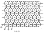
- Figure 3 is a schematic plan view of a blanket embodying the invention;
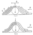
- Figure 4 shows a multi-layer blanket embodying the invention is use;
- Figure 5 shows another form of multi-layer blanket in use;
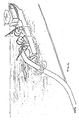
- Figure 6 shows a continuous length of blanket in typical installation procedure; and
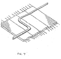
- Figure 7 shows blankets laid contiguously in the form of surface paving.
- Referring now to the drawings, Figures 1 and 2 show alternative forms of
segment 1 for use in a blanket embodying the invention. Each segment has awaist portion 2 where the segment is of maximum cross-sectional area. It is at this point that each segment touches the next adjacent segment in the blanket. The segment shown in Figure 1 is parallel-sided at one end and tapered at an angle between 25° and 30° toward the other end. This enables a blanket made of such segments to either sag-bend or over-bend depending on which way up the segments are used. The segment shown in Figure 2 tapers from thewaist portion 2 toward each end to an equal degree. Such segments can be used to make a blanket which will both sag-bend and over-bend as is required. - The segments are ideally 100 mm side length at the waist, have a total height between 150 mm and 200 mm, a taper of 20 mm-25 mm and are adapted to bend around radii down to approximately 300 mm.
- The segments are constructed from a settable compound comprising an aggregate, a filler and a binder. Materials which may be used are stone, granite, magnetite, haematite, sand, crushed limestone, cement and/or epoxy resin.
- The blankets have a variety of functions. One is to act as a ballast to hold pipe lines or structures in place in which case their prime characteristic is a high density. In such cases, the heaviest possible filler, such as haematite, is used and the product density may be as high as 3.7 tonnes/m3. Alternatively, the blanket may be provided to protect against anchor or construction line sawing in which case hardness is the prime characteristic required. In this case, a hard filler, such as granite is used, and the hardness may be as high as 7 on the Mohs scale. In some circumstances, both density and hardness may be required in which case a compromise is reached between the characteristics.
- The segments are formed into a blanket as shown in Figure 3. They are arranged with their
waist portions 2 touching and are held together by a network of ropes. Longitudinal lifting ropes 3 extend parallely through the blanket and are 10 mm to 20 mm thick three-strand nylon for individual blankets depending on length and up to 48 mm thick for continuous blanket lengths. The blanket may be lifted by means of these ropes either by both ends or by a single end. Each of these lifting ropes 3 extends through a line of segments. Each line of segments is connected to the next adjacent line by criss-crossing linking ropes 5. These linking ropes are generally 4 mm to 7 mm diameter three-strand nylon and extend diagonally through the blanket. At the edges of the blanket, they emerge from the segments in the form of loops 4. - Preferred individual blanket sizes are 2.5 m wide and up to 10 m long. This is a convenient size for lifting and transportation. However, for certain applications such as continuous pipe cover the blanket is produced in longer lengths and supplied on reels which can be attached to suitable vessels for installation as shown in Figure 6.
- Figure 4 shows one method of using the blanket.
Pipe line 6 is ballasted by a multi-layer blanket in which the layers are held together at the loops 4. Thelowermost layer 7 is the primary layer by which the entire assembly can be lifted. Theoutermost part 8 of this primary layer forms a scour skirt to adapt to changes in condition of the sea bed which may be caused by the introduction of the pipe line and its effect on water currents. At the central part 9 of the blanket, there is again only the primary layer since bulk here may tend to facilitate snagging and dislodgement of individual blankets by anchors, trawl boards etc. Between theoutermost part 8 and the central part 9 are a number ofsecondary layers 10 adapted to provide weight at the points where it will most advantageously hold the pipe line in position. - Figure 5 shows an alternative form in which two
layers 7 and 11 are provided each of identical width but the upper layer being of reduced length. A shear membrane (not shown) is provided between the layers to enable relative movement between them and accommodate the over-bend and sag-bend differentials. - Figure 6 shows the installation of a continuous length of blanket which would be particularly advantageous where mechanical protection is paramount. In this format snagging contingency and dislodgement is virtually eliminated.
- Figure 7 shows the blanket laid in contiguous paving on the sea bed enabling the perimeter to operate as a scour skirt to protect the elevation of the inner area for use as a constant elevation slip- pad under, for example a pipe line expansion loop or as a protected foundation raft for superimposed structures, pipe lines, equipment and the like.
- The blankets are manufactured by providing either a number of lower half-moulds which are assembled in continuous relationship or by providing a multi-form lower half-mould having a plurality of pockets. The lifting ropes 3 and linking
ropes 5 are interwoven and laid out on top of the lower half-mould and a corresponding upper half placed in position. The material is then cast into the mould thereby embedding the ropes. If so desired, the ropes can be welded or clamped together at their crossing points at the centre of each segment. - As stated above, the ideal shape for each segment is, in plan view, a regular hexagon. This enables flexibility in any direction and also helps prevent sawing by anchor cables or construction lines since there are no straight line joins through which the sawing can be facilitated.
- The blankets have been more specifically described in relation to stabilisation and protection of underwater structures and pipe lines, but other uses, both underwater and on land are intended. For example, the combination of integrated tie ropes at a point where they are protected from damage, and in a manner whereby structural integrity is not impaired by accidental destruction of one or more of the segments or its relative tie ropes, together with the multi-directional ductility of the blanket makes it ideal for paving any unstable surface.
- Also the use of 150 mm and 200 mm high segments in alternate horizontal rows on tidal embankments would afford unsurpassed resistance to tidal run-up which, together with its structural integrity, makes the blanket superior to alternative forms of protection for coastal and inland water embankments.
Claims (12)
Applications Claiming Priority (2)
| Application Number | Priority Date | Filing Date | Title |
|---|---|---|---|
| GB8407514 | 1984-03-22 | ||
| GB848407514A GB8407514D0 (en) | 1984-03-22 | 1984-03-22 | Flexible blanket |
Publications (3)
| Publication Number | Publication Date |
|---|---|
| EP0165659A2 EP0165659A2 (en) | 1985-12-27 |
| EP0165659A3 EP0165659A3 (en) | 1986-12-10 |
| EP0165659B1 true EP0165659B1 (en) | 1990-06-20 |
Family
ID=10558537
Family Applications (1)
| Application Number | Title | Priority Date | Filing Date |
|---|---|---|---|
| EP85302022A Expired - Lifetime EP0165659B1 (en) | 1984-03-22 | 1985-03-22 | Flexible blanket |
Country Status (5)
| Country | Link |
|---|---|
| EP (1) | EP0165659B1 (en) |
| AU (1) | AU583575B2 (en) |
| DE (1) | DE3578342D1 (en) |
| GB (2) | GB8407514D0 (en) |
| NO (1) | NO161932C (en) |
Families Citing this family (15)
| Publication number | Priority date | Publication date | Assignee | Title |
|---|---|---|---|---|
| GB2178127B (en) * | 1985-07-16 | 1989-05-10 | British Gas Corp | A stabilizing and protection mat for underwater installations |
| NO863063L (en) * | 1985-07-31 | 1987-02-02 | Waters Charles M | FLEXIBLE CARPET. |
| GB2212195A (en) * | 1987-10-16 | 1989-07-19 | Bukasa Ltd | Cellular stabilization and protective structure |
| GB2235943A (en) * | 1988-04-08 | 1991-03-20 | Waters Charles M | Erosion protection |
| GB2219334A (en) * | 1988-04-08 | 1989-12-06 | Bukasa Ltd | Erosion protection |
| US4940364A (en) * | 1988-10-14 | 1990-07-10 | Dlugosz Leonard T | Concrete construction units and multi-ply concrete composites made therefrom |
| WO1991016502A1 (en) * | 1990-04-17 | 1991-10-31 | Dunlop Limited | Outfall monitoring |
| GB2243390A (en) * | 1990-04-26 | 1991-10-30 | Dunlop Ltd | Protective blanket |
| EP0536241B1 (en) * | 1990-06-23 | 1995-03-15 | Dunlop Limited | Fluid supply device |
| GB2245556B (en) * | 1990-06-23 | 1995-02-22 | Dunlop Ltd | Fluid supply device |
| GB9015338D0 (en) * | 1990-07-12 | 1990-08-29 | Thatcher Keith | Flexible partition |
| GB2251642A (en) * | 1991-01-11 | 1992-07-15 | Waters Charles M | Flexible cellular stabilisation and protective structure |
| AR060197A1 (en) * | 2007-03-08 | 2008-06-04 | Revol Juan Carlos Amuchastegui | ARTICULATED STRUCTURE OF SURFACE DEVELOPMENT FOR SOIL CONSOLIDATION |
| RU2581349C1 (en) * | 2014-12-29 | 2016-04-20 | Общество с ограниченной ответственностью "МОРСТРОЙТЕХНОЛОГИЯ" | Protective wave-cancelling coating of slopes of marine hydraulic structures |
| RU2645229C1 (en) * | 2017-01-23 | 2018-02-19 | Федеральное государственное бюджетное научное учреждение "Российский научно-исследовательский институт проблем мелиорации" (ФГБНУ "РосНИИПМ") | Flexible protective concrete coating |
Family Cites Families (6)
| Publication number | Priority date | Publication date | Assignee | Title |
|---|---|---|---|---|
| US2454292A (en) * | 1946-04-05 | 1948-11-23 | Andrew B Pickett | Revetment mat |
| US2674856A (en) * | 1950-05-02 | 1954-04-13 | Frank I Louckes | Flexible revetment mat |
| GB2035504A (en) * | 1978-11-23 | 1980-06-18 | Larsen O | A system for protection of an installation on the floor of a body of water |
| CA1129218A (en) * | 1980-08-14 | 1982-08-10 | David H. Hansen | Flexible concrete for soil erosion prevention |
| GB2139676A (en) * | 1983-02-12 | 1984-11-14 | Ardon International Ltd | Improvements in or relating to a method of and device for use in preventing ground erosion and maintaining earth stability |
| EP0152232A3 (en) * | 1984-02-03 | 1986-03-19 | United Wire Group Public Limited Company | Stabilisation mat |
-
1984
- 1984-03-22 GB GB848407514A patent/GB8407514D0/en active Pending
-
1985
- 1985-03-13 GB GB08506539A patent/GB2156941B/en not_active Expired
- 1985-03-22 EP EP85302022A patent/EP0165659B1/en not_active Expired - Lifetime
- 1985-03-22 NO NO851162A patent/NO161932C/en unknown
- 1985-03-22 DE DE8585302022T patent/DE3578342D1/en not_active Expired - Lifetime
- 1985-12-31 AU AU51747/85A patent/AU583575B2/en not_active Ceased
Also Published As
| Publication number | Publication date |
|---|---|
| AU583575B2 (en) | 1989-05-04 |
| AU5174785A (en) | 1987-07-02 |
| NO161932B (en) | 1989-07-03 |
| NO161932C (en) | 1989-10-11 |
| DE3578342D1 (en) | 1990-07-26 |
| GB8407514D0 (en) | 1984-05-02 |
| GB8506539D0 (en) | 1985-04-17 |
| NO851162L (en) | 1985-09-23 |
| EP0165659A2 (en) | 1985-12-27 |
| EP0165659A3 (en) | 1986-12-10 |
| GB2156941A (en) | 1985-10-16 |
| GB2156941B (en) | 1987-03-11 |
Similar Documents
| Publication | Publication Date | Title |
|---|---|---|
| US4683156A (en) | Flexible blanket | |
| EP0165659B1 (en) | Flexible blanket | |
| US4242010A (en) | Method and means for protecting a sea bottom surface and an installation on same | |
| US7708495B1 (en) | Levee system | |
| US4477206A (en) | Flexible mattress-like element usable at ballast for immobilizing and protecting underwater pipelines | |
| US4370075A (en) | Revetment grids and mats | |
| US20240229398A1 (en) | Modular multi-form breakwater construction block molding system for molding different breakwater construction blocks having different performance characteristics | |
| US5632571A (en) | Concrete geomattress | |
| US6027285A (en) | Mat installation | |
| WO1997025483A1 (en) | Ice composite bodies | |
| US5129756A (en) | Apparatus for and method of coastal erosion control using massive sea block system | |
| US10400407B2 (en) | Modular wave-break and bulkhead system | |
| US4184786A (en) | Earth dam protective covering | |
| US4820079A (en) | Method of coastal erosion control using massive sea block system | |
| WO2018085525A1 (en) | Erosion control mat system | |
| EP0152232A2 (en) | Stabilisation mat | |
| GB2099054A (en) | Marine protective structures and modular block constructions therefor | |
| US3355894A (en) | Structure for use in river and sea | |
| US5507594A (en) | Method and apparatus for constructing an artificial reef | |
| WO1990001584A1 (en) | Seabed stabilisation mattresses | |
| US5975796A (en) | Vertical flow diversion mat system | |
| WO2023177382A1 (en) | The coastal interbloc reinforced medium variable geometry variable density modular revetment system | |
| CN212480524U (en) | Ballast protection pad | |
| US4954012A (en) | Method of coastal erosion control using massive sea block system | |
| CA1126040A (en) | Earth dam protective covering |
Legal Events
| Date | Code | Title | Description |
|---|---|---|---|
| PUAI | Public reference made under article 153(3) epc to a published international application that has entered the european phase |
Free format text: ORIGINAL CODE: 0009012 |
|
| AK | Designated contracting states |
Designated state(s): BE DE FR GB NL SE |
|
| 19A | Proceedings stayed before grant |
Effective date: 19851203 |
|
| PUAL | Search report despatched |
Free format text: ORIGINAL CODE: 0009013 |
|
| AK | Designated contracting states |
Kind code of ref document: A3 Designated state(s): BE DE FR GB NL SE |
|
| RAP1 | Party data changed (applicant data changed or rights of an application transferred) |
Owner name: WATERS, CHARLES MICHAEL |
|
| RIN1 | Information on inventor provided before grant (corrected) |
Inventor name: WATERS, CHARLES MICHAEL |
|
| 19F | Resumption of proceedings before grant (after stay of proceedings) |
Effective date: 19870701 |
|
| 17P | Request for examination filed |
Effective date: 19871218 |
|
| 17Q | First examination report despatched |
Effective date: 19880603 |
|
| DIN1 | Information on inventor provided before grant (deleted) | ||
| GRAA | (expected) grant |
Free format text: ORIGINAL CODE: 0009210 |
|
| RAP1 | Party data changed (applicant data changed or rights of an application transferred) |
Owner name: DUNLOP LIMITED |
|
| RIN1 | Information on inventor provided before grant (corrected) |
Inventor name: WATERS, CHARLES MICHAEL |
|
| AK | Designated contracting states |
Kind code of ref document: B1 Designated state(s): BE DE FR NL SE |
|
| REF | Corresponds to: |
Ref document number: 3578342 Country of ref document: DE Date of ref document: 19900726 |
|
| ET | Fr: translation filed | ||
| PLBE | No opposition filed within time limit |
Free format text: ORIGINAL CODE: 0009261 |
|
| STAA | Information on the status of an ep patent application or granted ep patent |
Free format text: STATUS: NO OPPOSITION FILED WITHIN TIME LIMIT |
|
| 26N | No opposition filed | ||
| PGFP | Annual fee paid to national office [announced via postgrant information from national office to epo] |
Ref country code: SE Payment date: 19921217 Year of fee payment: 9 |
|
| PGFP | Annual fee paid to national office [announced via postgrant information from national office to epo] |
Ref country code: BE Payment date: 19930105 Year of fee payment: 9 |
|
| PGFP | Annual fee paid to national office [announced via postgrant information from national office to epo] |
Ref country code: DE Payment date: 19930331 Year of fee payment: 9 |
|
| PGFP | Annual fee paid to national office [announced via postgrant information from national office to epo] |
Ref country code: FR Payment date: 19931215 Year of fee payment: 10 |
|
| PG25 | Lapsed in a contracting state [announced via postgrant information from national office to epo] |
Ref country code: SE Free format text: LAPSE BECAUSE OF NON-PAYMENT OF DUE FEES Effective date: 19940323 |
|
| PG25 | Lapsed in a contracting state [announced via postgrant information from national office to epo] |
Ref country code: BE Effective date: 19940331 |
|
| BERE | Be: lapsed |
Owner name: DUNLOP LTD Effective date: 19940331 |
|
| PG25 | Lapsed in a contracting state [announced via postgrant information from national office to epo] |
Ref country code: DE Effective date: 19941201 |
|
| EUG | Se: european patent has lapsed |
Ref document number: 85302022.0 Effective date: 19941010 |
|
| PG25 | Lapsed in a contracting state [announced via postgrant information from national office to epo] |
Ref country code: FR Free format text: LAPSE BECAUSE OF NON-PAYMENT OF DUE FEES Effective date: 19951130 |
|
| PGFP | Annual fee paid to national office [announced via postgrant information from national office to epo] |
Ref country code: NL Payment date: 19951220 Year of fee payment: 12 |
|
| REG | Reference to a national code |
Ref country code: FR Ref legal event code: ST |
|
| PG25 | Lapsed in a contracting state [announced via postgrant information from national office to epo] |
Ref country code: NL Effective date: 19971001 |
|
| NLV4 | Nl: lapsed or anulled due to non-payment of the annual fee |
Effective date: 19971001 |