EP0200741B1 - Zieldiskriminierung unter benutzung von mittelwertfiltern - Google Patents
Zieldiskriminierung unter benutzung von mittelwertfiltern Download PDFInfo
- Publication number
- EP0200741B1 EP0200741B1 EP85905014A EP85905014A EP0200741B1 EP 0200741 B1 EP0200741 B1 EP 0200741B1 EP 85905014 A EP85905014 A EP 85905014A EP 85905014 A EP85905014 A EP 85905014A EP 0200741 B1 EP0200741 B1 EP 0200741B1
- Authority
- EP
- European Patent Office
- Prior art keywords
- objects
- output signals
- median
- size range
- filter
- Prior art date
- Legal status (The legal status is an assumption and is not a legal conclusion. Google has not performed a legal analysis and makes no representation as to the accuracy of the status listed.)
- Expired
Links
Images


Classifications
-
- G—PHYSICS
- G06—COMPUTING OR CALCULATING; COUNTING
- G06T—IMAGE DATA PROCESSING OR GENERATION, IN GENERAL
- G06T7/00—Image analysis
- G06T7/60—Analysis of geometric attributes
Definitions
- the present invention relates generally to size discrimination systems and methods, and more particularly to size discrimination systems and methods which implement nonlinear median filtering techniques.
- State-of-the-art digital target identification systems utilize numerous image processing techniques to eliminate noise and unwanted clutter from images processed thereby.
- impulse noise may be removed from a video image by means of what is referred to as a median of medians operator.
- This is a computer algorithm which is implemented in hardware that processes digital video signals by means of median filters.
- the median filter comprises a sliding window encompassing an odd number of pixels.
- the center pixel in the window is replaced by the median of the pixels within the window.
- the median pixel value is that pixel value for which half of the pixel values are smaller or equal in value and half are larger or equal in value.
- median filtering is more effective in reducing the effect of discrete impulse noises than smoothly generated noise.
- image processing techniques for industrial purposes is their employment in the IC manufacture for defect detection.
- the image processing systems used in such a field are generally comparing a measured image from a structure to be tested with a predetermined design pattern.
- E.g. US-A-4,472,738 is relating to a pattern testing apparatus providing a first and a second area being defined on a two-dimensional pattern and discriminating means for calculating defect signals. If signals are received by said discriminating means emanating from picture cells forming said first and second areas, which are not in accordance with a predetermined design pattern, a defect signal is provided.
- Size determination is a significant discriminant in determining the presence of potential targets located in an image scene. Determining the relative sizes of potential targets and more importantly, excluding those objects from the image which are clearly not potential targets would be very advantageous.
- a size discrimination system in accordance with claim 1 and a method for producing signals indicative of objects whose sizes are within a predetermined size range in accordance with claim 6 which processes digitized image data and generates output signals which are indicative of objects whose sizes are in a predetermined size range. Objects whose sizes are outside the predetermined range are removed from th image.
- the system employs median and anti-median filter combinations to accomplish the desired size filtering.
- the system comprises first filter means for processing applied digitized signals (pixels) in order to discriminate objects which have a size within a first preselected range of sizes, and for providing first output signals indicative of objects whose sizes are within the first range.
- Second filter means processes the signals in order to discriminate objects which have a size within a second preselected range of sizes, and for providing second output signals indicative of objects whose sizes are within the second range.
- At least one of the first and second preselected ranges include object sizes which are within the predetermined size range.
- Third means comprising circuit means are coupled to the first and second filter means for coupling output signals from the first and second filters in a manner which generates the output signals which are indicative of only those objects whose sizes are in the predetermined size range.
- Such coupling may, for example, include a difference function.
- the size discrimination system of the present invention may comprise median and/or anti-median filter combinations.
- the median filter transmits signals indicative of objects whose sizes are larger than a particular size limit.
- the anti-median filter transmits signals indicative of objects whose sizes are smaller than a predetermined limit. Appropriate combining of the filter types allows for selective processing of object sizes in any predetermined size range.
- the size of object passed by the filter is related to the size of the window of the filter.
- One specific embodiment of the size discrimination system of the present invention comprises an anti-median filter serially coupled to a median filter.
- This combination comprises a bandpass arrangement in which the anti-median filter passes signals indicative of objects whose sizes are below an upper limit of the predetermined range of object sizes.
- the median filter then processes the signals output from the anti-median filter and passes only signals indicative of objects whose sizes are above a lower limit of the predetermined range. Accordingly, the output signals from the combination are indicative of objects whose sizes are within the predetermined range.
- a second specific embodiment is the counterpart of the above-described embodiment, wherein a median filter is followed serially by an anti-median filter. It should be clear that substantially the same bandpass filter arrangement is accomplished by this combination.
- Another embodiment of the size discrimination system comprises a parallel combination of median filters having separate size bandpass cutoffs which correspond to the upper and lower limits of the predetermined size range, respectively.
- the signal outputs of the two parallel median filters are then processed by a differencing circuit which subtracts the two signal outputs.
- These difference signals comprise signals which are indicative of objects whose sizes are within the predetermined range.
- the counterpart of the above-described parallel filter combination is a parallel filter embodiment comprised of anti-median filters whose bandpass cutoffs represent the upper and lower limits of the predetermined size range, respectively.
- a differencing circuit combines the output signals from the two anti-median filters in the same manner as described above. It should be clear that this anti-median filter combination accomplishes substantially the same result as the parallel median filter combination.
- the present invention also provides for a method of processing applied signals representative of an image scene and which produces output signals indicative of objects from the image scene that have sizes within a predetermined size range.
- the basic method comprises the steps of processing applied signals to provide first output signals indicative of objects that have a size within a first preselected size range.
- the second step is processing applied signals to provide second output signals indicative of objects that have a size within a second preselected size range.
- At least one of the two size ranges include sizes within the predetermined size range.
- the final step is coupling the signals from the first and second steps in a manner which provides output signals indicative of objects whose sizes are within the predetermined range.
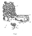
- the image scene 20 may include a forest 21, a tree 22, and a truck 23, or similarly sized objects.
- the present invention is generally employed as part of an image processing system, or target acquisition system, or the like.
- the purpose of the system is to identify and acquire target objects in the image scene 20.
- the imaging portion of the system may be a video or infrared imaging system operating in the visible or infrared portions of the spectrum, or a synthetic aperture radar system, or the like. These imaging systems produce digitized output signals, similar to video signals, which are representative of an image scene viewed thereby, such as the image scene 20 of FIG. 1.
- the size discrimination system of the present invention is employed to filter applied signals representative of the image scene 20 and provide a filtered output signal which has removed unwanted objects from the image scene 20, leaving only objects of potential interest.
- the present invention employs the use of median and anti-median filters.
- the median filter is comprised of a sliding window encompassing an odd number of pixels. The value of the center pixel in the window is replaced by the value of the median of the pixels within the window.
- the median pixel value is that pixel value for which half of the pixel values are smaller or equal in value and half are larger or equal in value.
- the median filter is nonlinear since the sum of medians is not equal to the median of sums.
- the median filter passes applied signals indicative of objects whose sizes are larger than a predetermined size.
- the anti-median filter is obtained by substracting a median filter value from the original applied input signal value at each pixel in the window. This is accomplished by passing applied signals and output signals from a median filter through a differencing circuit. The result is that the anti-median filter passes signals indicative of objects which are smaller than a predetermined size.
- the median filter as described herein is implemented by processing data from a cross-shaped window of pixels (windows of other shapes may also be used) in the image plane.
- the cross-shaped window may vary in size from three-by-three to fifteen-by-fifteen (or more) elements in size. Each element of the window is loaded with pixel data from the original image.
- the cross-shaped window is initialized to start in the top left hand corner of the image and is passed over the entire image pixel by pixel.
- the pixel magnitudes located within the elements of the window are sorted from the highest to lowest.
- the middle number in the list is the median of the list of numbers. This value has an equal amount of numbers lower and greater than it, and is usually different from the average.
- the large window median filter removes all objects less than one-half the size of the large window and the small window median filter removes all objects smaller than one-half the size of the small window.
- the objects remaining, after differencing the output of the two filters, are larger than one-half the size of the small window and smaller than one-half the size of the large window.
- the system 30 comprises a first median filter 31, which is coupled to a signal source 33, such as a video camera system, or infrared sensor system, or the like.
- the signal source 33 provides digitized output signals representative of the image scene 20 of FIG. 1.
- the first median filter 31 processes applied signals and provides first output signals indicative of objects whose sizes are within a first preselected size range.
- the first median filter 31 filters objects whose sizes are larger than a lower size limit of the predetermined range. This limit may be set at a size which is smaller than the truck 23, but larger than the tree 22 in FIG. 1, for example.
- a second median filter 34 is coupled in parallel to the signal source 33 and processes the applied signals to provide second output signals indicative of objects whose sizes are within a second preselected size range.
- the second median filter 34 filters objects whose sizes are larger than an upper limit of the predetermined size range. This limit may be set at a size which is larger than the truck 23 but smaller than the forest 21, for example.
- the signal outputs of the first and second median filters 31, 34 are coupled to a differencing circuit 35.
- the differencing circuit 35 processes the first and second output signals to provide third output signals which are the differences therebetween.
- the third output signals from the differencing circuit 35 include signals representative only of objects having a size within the predetermined size range.
- the differencing circuit 35 comprises means for coupling the signals from the two median filters 31, 34 to generate output signals which are indicative of objects whose sizes are in the predetermined size range.
- FIG. 2b illustrates the filtering performed by the first and second median filters 31, 34, respectively.
- the first median filter 31 passes objects larger than size S1.
- the second median filter 34 passes objects whose sizes are greater than size S2.
- the differencing circuit 35 substracts the output of the second filter 34 from the first filter 31 (S1-S2) which then is indicative of objects whose sizes are within the predetermined size range; namely, between sizes S1 and S2.
- FIG. 3a a second embodiment of the size discrimination system 30' of the present invention is shown.
- This embodiment is the anti-median counterpart of the embodiment of FIG. 2.
- First and second anti-median filters 36, 37 are coupled in parallel between the signal source 33 and the differencing circuit 35.
- the design and operation of this arrangement is substantially the same as the embodiment of FIG. 2a.
- the filtering operation of the parallel anti-median filter combination is shown in FIG. 3b.
- Substantially the same size range may be obtained by this filter combination as in the first embodiment.
- processing time is longer than in the first embodiment since each anti-median filter 36, 37 must perform its own differencing operation prior to application of signals to the differencing circuit 35.
- FIG. 4a shows a third embodiment of a size discrimination system 30'' in accordance with the principles of the invention.
- the system 30'' comprises an anti-median filter 36 serially coupled to a median filter 34.
- the means for coupling the signals to produce the desired size filtered output comprises the electrical connection 38 between the two filters 36, 34.
- the system 30'' operates such that the anti-median filter 36 passes objects having a size which is smaller than the first predetermined size. This size is selected to be larger than the truck 23 of FIG. 1, and hence an upper bound of the predetermined size range.
- the median filter 34 then processes the signals from the anti-median filter 36 and filters out those objects which are larger than the second predetermined size. This size is chosen to be smaller than the size of the truck 23 of FIG. 1, and represents a lower bound of the predetermined size range. Consequently, only signals indicative of objects which have sizes that are between the two size limits are passed by the filter combination.
- the filter operation of this embodiment is illustrated in FIG. 4b.
- FIG. 5a illustrates a fourth embodiment of a size discrimination system 30''' in accordance with the present invention.
- the system 30''' is a reversed serial filter combination which is substantially the same as the embodiment of FIG. 4a.
- the embodiment of FIG. 5a has the median and anti-median filters 34, 36 reversed in position.
- the system operates substantially the same as the system of FIG. 4a, and the filtering operation of this embodiment is shown in FIG. 5b.
- the method may be employed in processing video or other similar signals indicative of objects having various sizes, and is used to generate output signals that are representative of only objects whose sizes are within a predetermined size range.
- the first step in the method is processing the applied signals by means of a first filter to provide first output signals indicative of objects having a first preselected size range, as indicated in box 40.
- the second step is processing the signals by means of a second filter to provide second output signals indicative of objects having a second preselected size range, as indicated in box 42.
- the final step is coupling the first and second output signals in a manner which produces output signals indicative of objects whose sizes are within the predetermined size range, as indicated in box 44.
Landscapes
- Physics & Mathematics (AREA)
- Engineering & Computer Science (AREA)
- Geometry (AREA)
- Computer Vision & Pattern Recognition (AREA)
- General Physics & Mathematics (AREA)
- Theoretical Computer Science (AREA)
- Image Processing (AREA)
- Image Analysis (AREA)
Claims (6)
- Größenunterscheidungssystem (30) zur Verwendung in einem bildverarbeitenden System, welches Ausgangssignale bereitstellt, die die Größe von Objekten (21, 22, 23) anzeigen, deren Größen innerhalb eines vorherbestimmten Größenbereiches liegen, wobei das Größenunterscheidungssystem (30) aufweist:
eine Signalquelle (33), welche den Inhalt einer Bildszenerie (20) darstellt; dadurch gekennzeichnet, daß
das Größenunterscheidungssystem (30) desweiteren erste Filtervorrichtungen (31; 36) aufweist, zum Verarbeiten der Signale auf der Grundlage von Median-Berechnungen und zum Bereitstellen von ersten Ausgangssignalen, die die Größe von Objekten (21, 22, 23) in der Bildszenerie (20) anzeigen, deren Größen innerhalb eines ersten vorhergewählten Größenbereiches liegen, der sich von einer ersten vorhergewählten Größe erstreckt; und durch
zweite Filtervorrichtungen (34; 37), welche mit den ersten Filtervorrichtungen (31; 36) verbunden sind, zum Verarbeiten der Signale auf der Grundlage der Median-Berechnungen und zum Bereitstellen von zweiten Ausgangssignalen, welche Objekte (21, 22, 23) in der Bildszenerie (20) anzeigen, deren Größen innerhalb eines zweiten vorhergewählten Größenbereiches liegen, der sich von einer zweiten vorhergewählten Größe erstreckt; wobei
wenigstens einer der ersten und zweiten vorhergewählten Größenbereiche Objektgrößen umfaßt, welche innerhalb dem vorherbestimmten Größenbereich liegen; und durch
dritte Vorrichtungen (35), welche mit den ersten (31; 36) und zweiten (34; 37) Filtervorrichtungen verbunden sind, zum Koppeln von Ausgangssignalen aus den ersten (31; 36) und zweiten (34; 37) Filtervorrichtungen derartig, daß Ausgangssignale bereitgestellt werden, welche Objekte (21, 22, 23) in der Bildszenerie (20) anzeigen, deren Größen in dem vorherbestimmten Größenbereich liegen. - Größenunterscheidungssystem (30) nach Anspruch 1, wobei:
die ersten Filtervorrichtungen (31; 36) einen Anti-Medianfilter (36) aufweisen, der Signale hindurchläßt, die Objekte (21, 22, 23) in der Bildszenerie (20) anzeigen, deren Größen unterhalb einer oberen Grenze des vorherbestimmten Größenbereiches liegen; und
die zweiten Filtervorrichtungen (34; 37) einen Median-Filter (34) umfassen, welcher seriell mit dem Anti-Medianfilter (36) mittels den dritten Vorrichtungen (35) verbunden ist, zum Verarbeiten der dadurch bereitgestellten Ausgangssignale, und zum Hindurchlassen von Signalen, die Objekte (21, 22, 23) in der Bildszenerie (20) anzeigen, deren Größen oberhalb der unteren Grenze des vorherbestimmten Größenbereiches liegen;
der Medianfilter (34) Ausgangssignale bereitstellt, welche Objekte (21, 22, 23) in der Bildszenerie (20) anzeigen, deren Größen innerhalb des vorherbestimmten Größenbereiches liegen. - Größenunterscheidungssystem (30) nach Anspruch 1, wobei:
die ersten Filtervorrichtungen (31; 36) einen Medianfilter (31) aufweisen, welcher Signale hindurchläßt, die Objekte (21, 22, 23) in der Bildszenerie (20) anzeigen, deren Größen oberhalb einer unteren Begrenzung des vorherbestimmten Größenbereiches liegen; und
die zweiten Filtervorrichtungen (34; 37) einen Anti-Medianfilter (37) aufweisen, welcher seriell mit dem Medianfilter (31) mittels den dritten Vorrichtungen (35) verbunden ist, zum Verarbeiten der dadurch bereitgestellten Ausgangssignale, und zum Hindurchlassen von Signalen, welche Objekte (21, 22, 23) in der Bildszenerie (20) anzeigen, deren Größen unterhalb einer oberen Grenze des Größenbereiches liegen;
der Anti-Medianfilter (37) Ausgangssignale bereitstellt, die Objekte (21, 22, 23) in der Bildszenerie (20) anzeigen, deren Größen innerhalb des vorherbestimmten Größenbereiches liegen. - Größenunterscheidungssystem (30) nach Anspruch 1, wobei:
die ersten Filtervorrichtungen (31; 36) einen ersten Medianfilter (31) aufweisen, welcher Signale hindurchläßt, die Objekte (21, 22, 23) in der Bildszenerie (20) anzeigen, deren Größen oberhalb einer oberen Grenze des vorherbestimmten Größenbereiches liegen;
die zweiten Filtervorrichtungen (34; 37) einen zweiten Medianfilter (34) aufweisen, welcher parallel mit dem ersten Medianfilter (31) verbunden ist, zum Hindurchlassen von Signalen, die Objekte (21, 22, 23) in der Bildszenerie (20) anzeigen, deren Größen oberhalb einer unteren Begrenzung des vorherbestimmten Größenbereiches liegen; und
die dritten Vorrichtungen (35) einen Differenzschaltkreis (35) aufweisen, welcher mit den Ausgängen des ersten (31) und zweiten (34) Medianfilters verbunden ist, zum Subtrahieren der Ausgangssignale aus dem ersten Medianfilter (31) von den Ausgangssignalen aus dem zweiten Medianfilter (34), zum Bereitstellen von Ausgangssignalen, die Objekte (21, 22, 23) in der Bildszenerie (20) anzeigen, deren Größen innerhalb dem vorherbestimmten Größenbereich liegen. - Größenunterscheidungssystem (30) nach Anspruch 1, worin:
die ersten Filtervorrichtungen (31; 36) einen ersten Anti-Medianfilter (36) aufweisen, welcher Signale hindurchläßt, die Objekte (21, 22, 23) in der Bildszenerie (20) anzeigen, deren Größen unterhalb einer oberen Grenze des vorherbestimmten Größenbereiches liegen;
die zweiten Filtervorrichtungen (34; 37) einen zweiten Anti-Medianfilter (37) aufweisen, welcher parallel mit dem ersten Anti-Medianfilter (36) verbunden ist, zum Hindurchlassen von Signalen, die Objekte (21, 22, 23) in der Bildszenerie (20) anzeigen, deren Größen unterhalb einer unteren Begrenzung des vorherbestimmten Größenbereiches liegen; und
die dritten Vorrichtungen (35) einen Differenzschaltkreis (35) aufweisen, welcher mit den Ausgängen des ersten und zweiten Anti-Medianfilters (36; 37) verbunden ist, zum Subtrahieren der Ausgangssignale von dem zweiten Anti-Medianfilter (37) von den Ausgangssignalen von dem ersten Anti-Medianfilter (36), zum Bereitstellen von Ausgangssignalen, die Objekte (21, 22, 23) in der Bildszenerie (20) anzeigen, deren Größen innerhalb dem vorherbestimmten Größenbereich liegen. - Verfahren zum Verarbeiten von Signalen, welche eine Bildszenerie (20) darstellen, um Ausgangssignale bereitzustellen, die Objekte (21, 22, 23) in der Bildszenerie (20) anzeigen, die Größen innerhalb eines vorherbestimmten Größenbereiches aufweisen, gekennzeichnet durch:
Verarbeiten der Signale mittels erster Filtervorrichtungen (31; 36) auf der Grundlage von Median-Berechnungen, um erste Ausgangssignale bereitzustellen, welche Objekte (21, 22, 23) in der Bildszenerie (20) anzeigen, die eine Größe innerhalb eines ersten vorherbestimmten Größenbereiches aufweisen;
Verarbeiten der Signale durch zweite Filtervorrichtungen (34; 37) auf der Grundlage von Median-Berechnungen, um zweite Ausgangssignale bereitzustellen, welche Objekte (21, 22, 23) in der Bildszenerie (20) anzeigen, die eine Größe innerhalb eines zweiten vorherbestimmten Größenbereiches aufweisen; wobei
wenigstens einer der ersten und zweiten vorherbestimmten Größenbereiche Objektgrößen enthält, die innerhalb dem vorherbestimmten Größenbereich liegen; und
Koppeln der Ausgangssignale aus dem ersten und dem zweiten Schritt derartig, daß Ausgangssignale bereitgestellt werden, welche Objekte (21, 22, 23) in der Bildszenerie (20) anzeigen, deren Größen innerhalb dem vorherbestimmten Größenbereich liegen.
Applications Claiming Priority (2)
| Application Number | Priority Date | Filing Date | Title |
|---|---|---|---|
| US06/653,114 US4603430A (en) | 1984-09-21 | 1984-09-21 | Target discrimination utilizing median filters |
| US653114 | 1984-09-21 |
Publications (2)
| Publication Number | Publication Date |
|---|---|
| EP0200741A1 EP0200741A1 (de) | 1986-11-12 |
| EP0200741B1 true EP0200741B1 (de) | 1991-06-19 |
Family
ID=24619550
Family Applications (1)
| Application Number | Title | Priority Date | Filing Date |
|---|---|---|---|
| EP85905014A Expired EP0200741B1 (de) | 1984-09-21 | 1985-08-12 | Zieldiskriminierung unter benutzung von mittelwertfiltern |
Country Status (6)
| Country | Link |
|---|---|
| US (1) | US4603430A (de) |
| EP (1) | EP0200741B1 (de) |
| JP (1) | JPS62500268A (de) |
| DE (1) | DE3583292D1 (de) |
| IL (1) | IL76123A (de) |
| WO (1) | WO1986001920A1 (de) |
Families Citing this family (35)
| Publication number | Priority date | Publication date | Assignee | Title |
|---|---|---|---|---|
| US4739401A (en) * | 1985-01-25 | 1988-04-19 | Hughes Aircraft Company | Target acquisition system and method |
| US4868773A (en) * | 1985-03-15 | 1989-09-19 | Purdue Research Foundation | Digital filtering by threshold decomposition |
| JPH069061B2 (ja) * | 1986-03-26 | 1994-02-02 | 富士写真フイルム株式会社 | 画像デ−タの平滑化方法 |
| DE3631944A1 (de) * | 1986-09-19 | 1988-04-07 | Messerschmitt Boelkow Blohm | Einrichtung zur auswertung eines bildes zum zwecke der zielerkennung |
| US5712807A (en) * | 1987-10-21 | 1998-01-27 | Bangham; James Andrew | Pulse analyzing method and apparatus |
| DE3826285C2 (de) * | 1988-07-30 | 1995-02-16 | Univ Chicago | Verfahren und Anordnung zur Ermittlung von anormalen anatomischen Bereichen in einem digitalen Röntgenbild |
| US5218649A (en) * | 1990-05-04 | 1993-06-08 | U S West Advanced Technologies, Inc. | Image enhancement system |
| US5150426A (en) * | 1990-11-20 | 1992-09-22 | Hughes Aircraft Company | Moving target detection method using two-frame subtraction and a two quadrant multiplier |
| US5062142A (en) * | 1990-12-14 | 1991-10-29 | General Electric Company | Data processor producing a medial axis representation of an extended region |
| CA2060407C (en) * | 1991-03-22 | 1998-10-27 | Jack M. Sacks | Minimum difference processor |
| US5195544A (en) * | 1991-12-11 | 1993-03-23 | Vince Campagna | Nail catcher case |
| US5261012A (en) * | 1992-05-11 | 1993-11-09 | General Electric Company | Method and system for thinning images |
| US5371542A (en) * | 1992-06-23 | 1994-12-06 | The United States Of America As Represented By The Secretary Of The Navy | Dual waveband signal processing system |
| JPH08505741A (ja) * | 1993-01-16 | 1996-06-18 | バンガム,ジェイムズ・アンドリュー | 信号処理システム |
| DE69432772D1 (de) * | 1993-03-08 | 2003-07-10 | Canon Kk | Bildverarbeitungsvorrichtung und Aufzeichnungs-/Wiedergabegerät |
| US6118886A (en) * | 1993-03-30 | 2000-09-12 | The United States Of America As Represented By The United States Department Of Energy | Automatic target recognition apparatus and method |
| US5740266A (en) * | 1994-04-15 | 1998-04-14 | Base Ten Systems, Inc. | Image processing system and method |
| DE19849764B4 (de) | 1998-10-28 | 2004-10-21 | Siemens Ag | Bildgebende Diagnostikeinrichtung |
| CA2459823C (en) * | 2001-09-07 | 2012-04-03 | Intergraph Hardware Technologies Company | Method, device and computer program product for demultiplexing of video images |
| US7394944B2 (en) * | 2003-04-11 | 2008-07-01 | Seiko Epson Corporation | Method and system for finding spatial medians in a sliding window environment |
| US8031978B2 (en) * | 2004-06-30 | 2011-10-04 | Hitachi Aloka Medical, Ltd. | Method and apparatus of image processing to detect edges |
| US20060008178A1 (en) * | 2004-07-08 | 2006-01-12 | Seeger Adam A | Simulation of scanning beam images by combination of primitive features extracted from a surface model |
| US7912311B2 (en) * | 2005-03-21 | 2011-03-22 | Intel Corporation | Techniques to filter media signals |
| US8160382B2 (en) * | 2007-10-15 | 2012-04-17 | Lockheed Martin Corporation | Method of object recognition in image data using combined edge magnitude and edge direction analysis techniques |
| US8416986B2 (en) * | 2009-10-29 | 2013-04-09 | Raytheon Company | Methods and systems for processing data using non-linear slope compensation |
| US8738678B2 (en) | 2009-10-29 | 2014-05-27 | Raytheon Company | Methods and systems for determining an enhanced rank order value of a data set |
| CA2805730C (en) | 2010-07-21 | 2018-08-21 | Mbda Uk Limited | Image processing method |
| US10956485B2 (en) | 2011-08-31 | 2021-03-23 | Google Llc | Retargeting in a search environment |
| US10630751B2 (en) | 2016-12-30 | 2020-04-21 | Google Llc | Sequence dependent data message consolidation in a voice activated computer network environment |
| US8650188B1 (en) | 2011-08-31 | 2014-02-11 | Google Inc. | Retargeting in a search environment |
| US9002133B2 (en) * | 2013-02-27 | 2015-04-07 | Sharp Laboratories Of America, Inc. | Multi layered image enhancement technique |
| US9703757B2 (en) | 2013-09-30 | 2017-07-11 | Google Inc. | Automatically determining a size for a content item for a web page |
| US10431209B2 (en) | 2016-12-30 | 2019-10-01 | Google Llc | Feedback controller for data transmissions |
| US10614153B2 (en) | 2013-09-30 | 2020-04-07 | Google Llc | Resource size-based content item selection |
| RU2734655C1 (ru) * | 2020-03-17 | 2020-10-21 | федеральное государственное бюджетное образовательное учреждение высшего образования "Новгородский государственный университет имени Ярослава Мудрого" | Способ селекции изображения объекта на неоднородном фоне |
Family Cites Families (2)
| Publication number | Priority date | Publication date | Assignee | Title |
|---|---|---|---|---|
| GB1573142A (en) * | 1976-01-23 | 1980-08-13 | Hitachi Ltd | Apparatus and method for providing information relating to shape and/or position of an object |
| JPS57198851A (en) * | 1981-05-30 | 1982-12-06 | Nippon Kogaku Kk <Nikon> | Inspecting device for defect of pattern |
-
1984
- 1984-09-21 US US06/653,114 patent/US4603430A/en not_active Expired - Fee Related
-
1985
- 1985-08-12 WO PCT/US1985/001532 patent/WO1986001920A1/en not_active Ceased
- 1985-08-12 DE DE8585905014T patent/DE3583292D1/de not_active Expired - Fee Related
- 1985-08-12 JP JP60504434A patent/JPS62500268A/ja active Pending
- 1985-08-12 EP EP85905014A patent/EP0200741B1/de not_active Expired
- 1985-08-18 IL IL76123A patent/IL76123A/xx not_active IP Right Cessation
Also Published As
| Publication number | Publication date |
|---|---|
| US4603430A (en) | 1986-07-29 |
| DE3583292D1 (de) | 1991-07-25 |
| EP0200741A1 (de) | 1986-11-12 |
| IL76123A (en) | 1990-11-05 |
| IL76123A0 (en) | 1985-12-31 |
| JPS62500268A (ja) | 1987-01-29 |
| WO1986001920A1 (en) | 1986-03-27 |
Similar Documents
| Publication | Publication Date | Title |
|---|---|---|
| EP0200741B1 (de) | Zieldiskriminierung unter benutzung von mittelwertfiltern | |
| WO1986001920A2 (en) | Target discrimination utilizing median filters | |
| EP0476959B1 (de) | System und Verfahren zur Echtzeit-Mischung von Videobildern aus mehreren Quellen | |
| DE68910498T2 (de) | Signalverarbeitung zur autonomen erfassung von objekten in einem hintergrund von störechos. | |
| EP0020417B1 (de) | Elektronische bildverdeutlichung | |
| US5757977A (en) | Fuzzy logic filter for reducing noise and sharpening edges of digital image signals | |
| US5666441A (en) | Computer vision system to detect 3-D rectangular objects | |
| DE69708195T2 (de) | Detektion von beweglichen Objekten und von vorübergehenden Ereignissen aus den mit einer sich drehenden, bandförmigen Apertur gewonnenen Bildmessungen | |
| EP1496483B1 (de) | Verfahren und Einrichtung zur Detektion von Flammen | |
| Vernon | Decoupling Fourier components of dynamic image sequences: a theory of signal separation, image segmentation, and optical flow estimation | |
| Mitchell et al. | Segmentation and classification of targets in FUR imagery | |
| Hsueh et al. | Adaptive causal anomaly detection for hyperspectral imagery | |
| DE4416349A1 (de) | Unterdrückung von Störflecken unter Verwendung der Zusammenhangseigenschaft | |
| EP0585035B1 (de) | Realzeit-Zusammenhangalgorithmussystem | |
| Choudhary et al. | A novel approach for edge detection for blurry images by using digital image processing | |
| DE69325197T2 (de) | Diskriminierung des Verhältnis von Amplituden in MTI-Prozessoren | |
| EP0514390A1 (de) | Verfahren zur bestimmung der momentanen lage und form von bewegten objekten und zu deren anzeige als binärbild. | |
| Gambhir et al. | Wavelet based fusion of fuzzy enhanced images captured under improper illumination | |
| Chiandussi et al. | Nonlinear unsharp masking for the enhancement of document images | |
| Viero et al. | Non-moving regions preserving median filters for image sequence filtering | |
| Kulemin et al. | Methodology of multichannel radar image processing and interpretation | |
| Economou et al. | A novel edge detector based on nonlinear local operations | |
| Faniso-Mnyaka et al. | Image quality assessment methods for near-infrared wildfire imagery | |
| US6426684B1 (en) | Point detect filter | |
| Ling et al. | Fusion of images with different spatial resolution |
Legal Events
| Date | Code | Title | Description |
|---|---|---|---|
| PUAI | Public reference made under article 153(3) epc to a published international application that has entered the european phase |
Free format text: ORIGINAL CODE: 0009012 |
|
| 17P | Request for examination filed |
Effective date: 19860516 |
|
| AK | Designated contracting states |
Kind code of ref document: A1 Designated state(s): DE FR GB IT NL SE |
|
| 17Q | First examination report despatched |
Effective date: 19890602 |
|
| GRAA | (expected) grant |
Free format text: ORIGINAL CODE: 0009210 |
|
| AK | Designated contracting states |
Kind code of ref document: B1 Designated state(s): DE FR GB IT NL SE |
|
| ET | Fr: translation filed | ||
| REF | Corresponds to: |
Ref document number: 3583292 Country of ref document: DE Date of ref document: 19910725 |
|
| ITF | It: translation for a ep patent filed | ||
| PLBE | No opposition filed within time limit |
Free format text: ORIGINAL CODE: 0009261 |
|
| STAA | Information on the status of an ep patent application or granted ep patent |
Free format text: STATUS: NO OPPOSITION FILED WITHIN TIME LIMIT |
|
| 26N | No opposition filed | ||
| EAL | Se: european patent in force in sweden |
Ref document number: 85905014.8 |
|
| REG | Reference to a national code |
Ref country code: GB Ref legal event code: 732E |
|
| PGFP | Annual fee paid to national office [announced via postgrant information from national office to epo] |
Ref country code: FR Payment date: 19990709 Year of fee payment: 15 |
|
| PGFP | Annual fee paid to national office [announced via postgrant information from national office to epo] |
Ref country code: SE Payment date: 19990716 Year of fee payment: 15 Ref country code: GB Payment date: 19990716 Year of fee payment: 15 |
|
| PGFP | Annual fee paid to national office [announced via postgrant information from national office to epo] |
Ref country code: NL Payment date: 19990721 Year of fee payment: 15 |
|
| PGFP | Annual fee paid to national office [announced via postgrant information from national office to epo] |
Ref country code: DE Payment date: 19990726 Year of fee payment: 15 |
|
| PG25 | Lapsed in a contracting state [announced via postgrant information from national office to epo] |
Ref country code: GB Free format text: LAPSE BECAUSE OF NON-PAYMENT OF DUE FEES Effective date: 20000812 |
|
| PG25 | Lapsed in a contracting state [announced via postgrant information from national office to epo] |
Ref country code: SE Free format text: LAPSE BECAUSE OF NON-PAYMENT OF DUE FEES Effective date: 20000813 |
|
| PG25 | Lapsed in a contracting state [announced via postgrant information from national office to epo] |
Ref country code: NL Free format text: LAPSE BECAUSE OF NON-PAYMENT OF DUE FEES Effective date: 20010301 |
|
| GBPC | Gb: european patent ceased through non-payment of renewal fee |
Effective date: 20000812 |
|
| EUG | Se: european patent has lapsed |
Ref document number: 85905014.8 |
|
| PG25 | Lapsed in a contracting state [announced via postgrant information from national office to epo] |
Ref country code: FR Free format text: LAPSE BECAUSE OF NON-PAYMENT OF DUE FEES Effective date: 20010430 |
|
| NLV4 | Nl: lapsed or anulled due to non-payment of the annual fee |
Effective date: 20010301 |
|
| PG25 | Lapsed in a contracting state [announced via postgrant information from national office to epo] |
Ref country code: DE Free format text: LAPSE BECAUSE OF NON-PAYMENT OF DUE FEES Effective date: 20010501 |
|
| REG | Reference to a national code |
Ref country code: FR Ref legal event code: ST |