EP0200561A2 - Improved pipe coupling - Google Patents
Improved pipe coupling Download PDFInfo
- Publication number
- EP0200561A2 EP0200561A2 EP86303360A EP86303360A EP0200561A2 EP 0200561 A2 EP0200561 A2 EP 0200561A2 EP 86303360 A EP86303360 A EP 86303360A EP 86303360 A EP86303360 A EP 86303360A EP 0200561 A2 EP0200561 A2 EP 0200561A2
- Authority
- EP
- European Patent Office
- Prior art keywords
- coupling
- coupling part
- valve
- body portion
- hollow interior
- Prior art date
- Legal status (The legal status is an assumption and is not a legal conclusion. Google has not performed a legal analysis and makes no representation as to the accuracy of the status listed.)
- Granted
Links
Images


Classifications
-
- F—MECHANICAL ENGINEERING; LIGHTING; HEATING; WEAPONS; BLASTING
- F16—ENGINEERING ELEMENTS AND UNITS; GENERAL MEASURES FOR PRODUCING AND MAINTAINING EFFECTIVE FUNCTIONING OF MACHINES OR INSTALLATIONS; THERMAL INSULATION IN GENERAL
- F16L—PIPES; JOINTS OR FITTINGS FOR PIPES; SUPPORTS FOR PIPES, CABLES OR PROTECTIVE TUBING; MEANS FOR THERMAL INSULATION IN GENERAL
- F16L37/00—Couplings of the quick-acting type
- F16L37/28—Couplings of the quick-acting type with fluid cut-off means
- F16L37/38—Couplings of the quick-acting type with fluid cut-off means with fluid cut-off means in only one of two pipe-end fittings
- F16L37/40—Couplings of the quick-acting type with fluid cut-off means with fluid cut-off means in only one of two pipe-end fittings with a lift valve being opened automatically when the coupling is applied
- F16L37/42—Couplings of the quick-acting type with fluid cut-off means with fluid cut-off means in only one of two pipe-end fittings with a lift valve being opened automatically when the coupling is applied the valve having an axial bore communicating with lateral apertures
-
- F—MECHANICAL ENGINEERING; LIGHTING; HEATING; WEAPONS; BLASTING
- F16—ENGINEERING ELEMENTS AND UNITS; GENERAL MEASURES FOR PRODUCING AND MAINTAINING EFFECTIVE FUNCTIONING OF MACHINES OR INSTALLATIONS; THERMAL INSULATION IN GENERAL
- F16L—PIPES; JOINTS OR FITTINGS FOR PIPES; SUPPORTS FOR PIPES, CABLES OR PROTECTIVE TUBING; MEANS FOR THERMAL INSULATION IN GENERAL
- F16L37/00—Couplings of the quick-acting type
- F16L37/08—Couplings of the quick-acting type in which the connection between abutting or axially overlapping ends is maintained by locking members
- F16L37/084—Couplings of the quick-acting type in which the connection between abutting or axially overlapping ends is maintained by locking members combined with automatic locking
- F16L37/0841—Couplings of the quick-acting type in which the connection between abutting or axially overlapping ends is maintained by locking members combined with automatic locking by means of a transversally slidable locking member surrounding the tube
Definitions
- My present invention comprises an improved pipe coupling.
- Pipe couplings for coupling two sections of pipe together, or for coupling the end of a pipe to a fitting such as a tap or a machine such as a pump or the like are known in various forms.
- Such couplings comprise two major coupling parts, a first part which comprises a spigot which is in use engaged into the end of a section of pipe to be coupled and a second part which is connectable to a fitting or wliich comprises a similar spigot so that it can be fitted to a second section of pipe.
- first part which comprises a spigot which is in use engaged into the end of a section of pipe to be coupled
- a second part which is connectable to a fitting or wliich comprises a similar spigot so that it can be fitted to a second section of pipe.
- the pipe or pipe and fitting are coupled by connecting the coupling parts together.
- My invention provides an improved form of such coupling.
- my invention may be said to comprise a pipe coupling of the type comprising a first coupling part connectable to a pipe or fitting and including a body portion and a second coupling part connectable to a pipe or fitting and composing a hollow interior adapted to receive the body portion of the first coupling part in sealing engagement, characterised in that the body portion of the said first coupling part includes an annular recess and in that the said second coupling part includes a transverse slot formed therein across said hollow interior and a release bar slidably mounted in the said transverse slot and comprising an aperture thercthrough of a diameter similar to the diameter of the said first coupling part body portion, said release bar being movable between a first position wherein said aperture is substantially aligned with said hollow interior such that said body portion can be entered into or removed from the said hollow interior and a second position wherein the said aperture is offset from the said hollow interior such that an operative portion of the periphery of said aperture engages said annular recess of the body portion of the said first coupling
- the coupling of the invention includes in one of the coupling parts multi-stage flow valving arranged to control the flow of fluid through the coupling part and to be caused to open by connection of the coupling parts together, the flow valving otherwise being closed when the coupling parts are separated to prevent the escape of fluid.
- Reference numerals 1 and 2 in all figures of the drawings indicate the first and second coupling parts of both of the preferred forms of the coupling, which are suitably formed from a plastics material such as polythene, alkathene or nylon, or brass or the like.
- the first coupling part 1 generally comprises a spigot 3 and a body portion 4, which is preferably generally cylindrical in shape as shown.
- the body portion 4 comprises an annular recess 5, which is preferably shaped as shown having a first substantially vertical wall 5a adjacent the nose of the body portion 4 and a sloping rear wall 5b extending towards the rear of the body portion.
- the coupling part 1 may be secured to the end of a pipe by a conventional hose clip or alternatively by way of the arrangement snown, wherein a nut 6 (shown in Fig. 1) carried on a threaded boss portion 7 is arranged to be screwed to engage with its forward threads the exterior of the end of a pipe engaged on to the spigot 3.
- the nut 6 has a tapered interior and the spigot 3 can have a generally tapered exterior as shown.
- the exterior of the nut can be suitably ribbed as indicated at 8, to enable it to be readily gripped in use.
- Such an arrangement is described in my New Zealand patent specification No. 195771/200149 which is incorporated herein by reference.
- the second coupling part 2 is in the forms of coupling shown, at one end adapted to be connected to a fitting such as a tap, and includes a screw threaded portion 9 as shown. It could alternatively comprise a suitable spigot, for example, enabling the second coupling part to be connected to the end of another section of piping.
- the coupling could comprise as an accessory, a joiner tail adapted to be screwed into the threaded portion 9 and having a spigot in this regard.
- the second coupling part comprises a hollow interior 10 adapted to receive the body portion 4 of the first coupling part when the coupling parts are connected together.
- the coupling part 2 is shaped at 11 as shown so as to mount a longitudinally extending sealing member 12 formed of rubber or a like sealing material.
- the sealing member 12 has a circular sealing ring portion 12a adapted to seal against the end of a tap fitting onto which the second coupling part is fitted, and a portion 12b arranged to extend into and engage with the first coupling part in use (see Fig. 3).
- a transverse slot 13 is formed in the second coupling part across the hollow interior thereof as shown.
- a release bar 14 which in the preferred form shown is generally square in peripheral shape, is slidably mounted in the transverse slot 13 such that it can slide therein in the direction of arrows A.
- the sliding movement of the release bar 14 is limited and the release bar is retained in the transverse slot by nibs 15 (see Fig. 4) formed on either upper edge of the transverse slot, which engage into slight recesses 16 formed at either upper corner of the release bar 14 such that at the full extent of the outward movement of the release bar the nibs 15 will abut the bottom of the recesses 16.
- the release bar 14 has an aperture 17 therethrough as shown, which is of a diameter similar to the diameter of the body portion 4 of the coupling part 1.
- the release bar is movable between a first position wherein its aperture 17 is aligned with the hollow interior of the coupling part 2 (not shown in the drawings) and a second position (shown in the drawings and particularly in Fig. 4) wherein the aperture 17 is offset from the hollow interior.
- the relcase bar is resiliently urged towards the second position, in the preferred forms shown by spring legs 18 formed on the bottom of the release bar as shown.
- spring legs 18 When the release bar is moved from its second position to its first position, by manual pressure applied to its top 14a, the spring legs 18 will flex inwardly towards each other and be collapsed. When manual pressure is removed they will resiliently flex outwardly to urge the release bar back to its second position.
- other arrangements of urging means for the release bar may be provided.
- the coupling parts are connected by engaging the coupling part 1 and, specifically, by entering the body portion 4 into the hollow interior 10.
- the release bar 14 will be urged towards its normal second position and the arrangement is such that the release bar operative portion 14b engages into the annular recess 5 to retain the coupling part 1 in position and to secure the coupling.
- the coupling parts can be disconnected and the coupling part 1 removed from the coupling part 2 by pressing the top of the release bar 14a to move the release bar 14 to its first position, and withdrawing the coupling part 1.
- the release bar is able to be moved from its normal second position to its first position against the urging of the spring legs 18 by the engagement of the nose of the body portion 4 against the operative position 14b of the release bar as the coupling parts arc brought together, so that the first coupling part 1 may be 'snapped into' the second coupling part 2.
- the operative portion 14b of the release bar is preferably sloped towards the entry to the hollow interior 10 as shown.
- Couplings in accordance with the invention may incorporate a self-sealing flow valve arranged to prevent the flow of liquid from one coupling part when the coupling parts are disconnected.
- the second preferred forn coupling of the invention shown in Figs. 5 and 6 includes a particularly preferred form of two stage flow valving.
- the valving is incorporated in the second coupling part 2 which would normally be on the 'upstream' side of the coupling so that when the coupling parts arc disconnected the flow of fluid from the upstream pipe or fitting is prevented.
- the valving is operated to enable the flow of fluid through the coupling.
- the valving comprises a valve member 28 and a valve head 29.
- the valve member 28 is longitudinally slidably movable within the coupling part 2 between the closed position shown in Fig. 5 and the open position shown in Fig. 6.
- the valve member 28 has a valve body portion 28a having a hollow valve interior which is open at one end 28c.
- the valve member 28 terminates at its other end in an extending valve stem 28b as shown.
- Ports 30 arc providcd in the valve member 28 to communicate the hollow interior of the body portion 28a with the exterior, adjacent the base of the stem 28b.
- the valve member 28 is slidably mounted in the second coupling part 2 between an open and a closed position, through an aperture the upper peripheral edge of which forms a major valve seat.
- the valve member is mounted by way of the rubber scaling member 12.
- the upper peripheral edge 31 of this aperture forms the major valve seat against which the valve head 29 is adapted to engage when the valving is closed.
- the sealing member 12 is a friction fit within the coupling part 2 and has a thin walled collapsible end portion 32 which in turn is a friction fit about the body portion of the valve 28 adjacent its end 28c as shown.
- the valve head 29 is loosely mounted about the valve stem 28b as shown.
- the valve head 29 is circular in plan view (not shown) and the stem 28b-of the valve member 28 extends axially through an aperture 33 in the valve head 29.
- the upper edge 33a of this aperture 32 forms a minor valve seat.
- the valve head is retained on the valve stem 28b by an O-ring 34 which forms an enlargcd end portion of the same and which is adapted to engage the minor valve seat 33a when the valving is closed.
- valve head 29 engages the major valve seat 31 and the 0-ring 34 in turn engages the minor valve seat 33a in the valve head, so that fluid flow past the valve is prevented.
- valving will be maintained in this closed position by fluid pressure on the upstream side of the valve.
- the coupling part 1 When the coupling is connected, as the coupling parts 1 and 2 are brought together, the coupling part 1 contacts the end 28c of the valve member 28 and moves same such that the valve stem 28b moves through the valve head 29.
- the 0-ring 34 unseats from the minor seat 33a allowing a small initial flow of fluid through the valve head aperture 33 around the stem 28b.
- This flow of water contacts the major valve seat 31a assisting in lifting the valve head 29 therefrom so that as the coupling part 1 and valve member 28 moves further and physically lifts the valve head 29 from the seat 31a this initial water flow will tend to release pressure on the upstream side of the coupling to assist in enabling same.
- the valve head 29 may be shaped so -as to assist this initial water flow lifting action. It is preferred, for example, for the bottom of the valve head to include radially extending slots, so that it has a generally inverted castellated shape (which is shown in Figs 5 and 6).
Landscapes
- Engineering & Computer Science (AREA)
- General Engineering & Computer Science (AREA)
- Mechanical Engineering (AREA)
- Quick-Acting Or Multi-Walled Pipe Joints (AREA)
Abstract
Description
- My present invention comprises an improved pipe coupling.
- Pipe couplings for coupling two sections of pipe together, or for coupling the end of a pipe to a fitting such as a tap or a machine such as a pump or the like are known in various forms. Typically such couplings comprise two major coupling parts, a first part which comprises a spigot which is in use engaged into the end of a section of pipe to be coupled and a second part which is connectable to a fitting or wliich comprises a similar spigot so that it can be fitted to a second section of pipe. In use the pipe or pipe and fitting are coupled by connecting the coupling parts together.
- My invention provides an improved form of such coupling.
- In broad terms my invention may be said to comprise a pipe coupling of the type comprising a first coupling part connectable to a pipe or fitting and including a body portion and a second coupling part connectable to a pipe or fitting and composing a hollow interior adapted to receive the body portion of the first coupling part in sealing engagement, characterised in that the body portion of the said first coupling part includes an annular recess and in that the said second coupling part includes a transverse slot formed therein across said hollow interior and a release bar slidably mounted in the said transverse slot and comprising an aperture thercthrough of a diameter similar to the diameter of the said first coupling part body portion, said release bar being movable between a first position wherein said aperture is substantially aligned with said hollow interior such that said body portion can be entered into or removed from the said hollow interior and a second position wherein the said aperture is offset from the said hollow interior such that an operative portion of the periphery of said aperture engages said annular recess of the body portion of the said first coupling part when same is received in said hollow interior to retain same therein, and said release bar being resiliently urged towards said second position and manually movable therefrom to said first position.
- In one preferred form the coupling of the invention includes in one of the coupling parts multi-stage flow valving arranged to control the flow of fluid through the coupling part and to be caused to open by connection of the coupling parts together, the flow valving otherwise being closed when the coupling parts are separated to prevent the escape of fluid.
- Two preferred forms of the coupling of the invention are illustrated in the accompanying drawings, wherein :
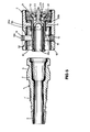
- FIG. 1 is a perspective view of the two parts of the first preferred form coupling, which does not include flow valving, when separated,
- FIG. 2 is a longitudinal cross-sectional view of the first preferred form coupling parts when separated, along line 1-1 of Fig. 1,
- FIG. 3 is a longitudinal cross-sectional view of the first preferred form coupling parts when connected together,
- FIG. 4 is a transverse cross-sectional view of the second coupling part of the first preferred form coupling, along lines II-II of FIG. 2,
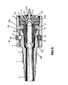
- FIG. 5 is a longitudinal cross-sectional view of the two parts of the second preferred form coupling, which includes flow valving, when separated, and
- FIG. 6 is a longitudinal cross-sectional view of the two parts of the second preferred form coupling when coupled together.
-
Reference numerals 1 and 2 in all figures of the drawings indicate the first and second coupling parts of both of the preferred forms of the coupling, which are suitably formed from a plastics material such as polythene, alkathene or nylon, or brass or the like. - The first coupling part 1 generally comprises a
spigot 3 and abody portion 4, which is preferably generally cylindrical in shape as shown. Thebody portion 4 comprises anannular recess 5, which is preferably shaped as shown having a first substantially vertical wall 5a adjacent the nose of thebody portion 4 and a slopingrear wall 5b extending towards the rear of the body portion. The coupling part 1 may be secured to the end of a pipe by a conventional hose clip or alternatively by way of the arrangement snown, wherein a nut 6 (shown in Fig. 1) carried on a threadedboss portion 7 is arranged to be screwed to engage with its forward threads the exterior of the end of a pipe engaged on to thespigot 3. The nut 6 has a tapered interior and thespigot 3 can have a generally tapered exterior as shown. The exterior of the nut can be suitably ribbed as indicated at 8, to enable it to be readily gripped in use. Such an arrangement is described in my New Zealand patent specification No. 195771/200149 which is incorporated herein by reference. - The
second coupling part 2, is in the forms of coupling shown, at one end adapted to be connected to a fitting such as a tap, and includes a screw threadedportion 9 as shown. It could alternatively comprise a suitable spigot, for example, enabling the second coupling part to be connected to the end of another section of piping. The coupling could comprise as an accessory, a joiner tail adapted to be screwed into the threadedportion 9 and having a spigot in this regard. At its other end the second coupling part comprises ahollow interior 10 adapted to receive thebody portion 4 of the first coupling part when the coupling parts are connected together. In the preferred forms thecoupling part 2 is shaped at 11 as shown so as to mount a longitudinally extending sealingmember 12 formed of rubber or a like sealing material. The sealingmember 12 has a circularsealing ring portion 12a adapted to seal against the end of a tap fitting onto which the second coupling part is fitted, and aportion 12b arranged to extend into and engage with the first coupling part in use (see Fig. 3). - A
transverse slot 13 is formed in the second coupling part across the hollow interior thereof as shown. Arelease bar 14 which in the preferred form shown is generally square in peripheral shape, is slidably mounted in thetransverse slot 13 such that it can slide therein in the direction of arrows A. The sliding movement of therelease bar 14 is limited and the release bar is retained in the transverse slot by nibs 15 (see Fig. 4) formed on either upper edge of the transverse slot, which engage intoslight recesses 16 formed at either upper corner of therelease bar 14 such that at the full extent of the outward movement of the release bar thenibs 15 will abut the bottom of therecesses 16. - The
release bar 14 has anaperture 17 therethrough as shown, which is of a diameter similar to the diameter of thebody portion 4 of the coupling part 1. The release bar is movable between a first position wherein itsaperture 17 is aligned with the hollow interior of the coupling part 2 (not shown in the drawings) and a second position (shown in the drawings and particularly in Fig. 4) wherein theaperture 17 is offset from the hollow interior. The relcase bar is resiliently urged towards the second position, in the preferred forms shown byspring legs 18 formed on the bottom of the release bar as shown. When the release bar is moved from its second position to its first position, by manual pressure applied to itstop 14a, thespring legs 18 will flex inwardly towards each other and be collapsed. When manual pressure is removed they will resiliently flex outwardly to urge the release bar back to its second position. In other forms of the invention other arrangements of urging means for the release bar may be provided. - In use of both preferred forms of coupling the coupling parts are connected by engaging the coupling part 1 and, specifically, by entering the
body portion 4 into thehollow interior 10. When thebody portion 4 is fully home within thehollow interior 10 therelease bar 14 will be urged towards its normal second position and the arrangement is such that the release baroperative portion 14b engages into theannular recess 5 to retain the coupling part 1 in position and to secure the coupling. The coupling parts can be disconnected and the coupling part 1 removed from thecoupling part 2 by pressing the top of therelease bar 14a to move therelease bar 14 to its first position, and withdrawing the coupling part 1. While the arrangement could be such that such manual movement of the release bar is also required to enable the coupling parts to be connected, it is preferred that the release bar is able to be moved from its normal second position to its first position against the urging of thespring legs 18 by the engagement of the nose of thebody portion 4 against theoperative position 14b of the release bar as the coupling parts arc brought together, so that the first coupling part 1 may be 'snapped into' thesecond coupling part 2. - To facilitate this the
operative portion 14b of the release bar is preferably sloped towards the entry to thehollow interior 10 as shown. - Couplings in accordance with the invention may incorporate a self-sealing flow valve arranged to prevent the flow of liquid from one coupling part when the coupling parts are disconnected.
- The second preferred forn coupling of the invention shown in Figs. 5 and 6 includes a particularly preferred form of two stage flow valving. The valving is incorporated in the
second coupling part 2 which would normally be on the 'upstream' side of the coupling so that when the coupling parts arc disconnected the flow of fluid from the upstream pipe or fitting is prevented. When the coupling parts are connected togcthcr the valving is operated to enable the flow of fluid through the coupling. In the second preferred form coupling shown the valving comprises avalve member 28 and avalve head 29. Thevalve member 28 is longitudinally slidably movable within thecoupling part 2 between the closed position shown in Fig. 5 and the open position shown in Fig. 6. Thevalve member 28 has avalve body portion 28a having a hollow valve interior which is open at oneend 28c. Thevalve member 28 terminates at its other end in an extendingvalve stem 28b as shown.Ports 30 arc providcd in thevalve member 28 to communicate the hollow interior of thebody portion 28a with the exterior, adjacent the base of thestem 28b. - The
valve member 28 is slidably mounted in thesecond coupling part 2 between an open and a closed position, through an aperture the upper peripheral edge of which forms a major valve seat. In the arrangement shown the valve member is mounted by way of therubber scaling member 12. The upperperipheral edge 31 of this aperture forms the major valve seat against which thevalve head 29 is adapted to engage when the valving is closed. The sealingmember 12 is a friction fit within thecoupling part 2 and has a thin walledcollapsible end portion 32 which in turn is a friction fit about the body portion of thevalve 28 adjacent itsend 28c as shown. - The
valve head 29 is loosely mounted about thevalve stem 28b as shown. Thevalve head 29 is circular in plan view (not shown) and thestem 28b-of thevalve member 28 extends axially through anaperture 33 in thevalve head 29. Theupper edge 33a of thisaperture 32 forms a minor valve seat. The valve head is retained on thevalve stem 28b by an O-ring 34 which forms an enlargcd end portion of the same and which is adapted to engage theminor valve seat 33a when the valving is closed. - In use when the coupling parts are disconneted as shown in Fig. 5 the
valve head 29 engages themajor valve seat 31 and the 0-ring 34 in turn engages theminor valve seat 33a in the valve head, so that fluid flow past the valve is prevented. In use the valving will be maintained in this closed position by fluid pressure on the upstream side of the valve. - When the coupling is connected, as the
coupling parts 1 and 2 are brought together, the coupling part 1 contacts theend 28c of thevalve member 28 and moves same such that thevalve stem 28b moves through thevalve head 29. The 0-ring 34 unseats from theminor seat 33a allowing a small initial flow of fluid through thevalve head aperture 33 around thestem 28b. This flow of water contacts the major valve seat 31a assisting in lifting thevalve head 29 therefrom so that as the coupling part 1 andvalve member 28 moves further and physically lifts thevalve head 29 from the seat 31a this initial water flow will tend to release pressure on the upstream side of the coupling to assist in enabling same. - The
valve head 29 may be shaped so -as to assist this initial water flow lifting action. It is preferred, for example, for the bottom of the valve head to include radially extending slots, so that it has a generally inverted castellated shape (which is shown in Figs 5 and 6). - The foregoing describes my invention including preferred forms thereof. Alterations and modifications as will be obvious to those skilled in the art are intended to be incorporated within the scope hereof, which is defined in the following claims.
Claims (8)
Applications Claiming Priority (4)
| Application Number | Priority Date | Filing Date | Title |
|---|---|---|---|
| NZ211983 | 1985-05-03 | ||
| NZ211983A NZ211983A (en) | 1985-05-03 | 1985-05-03 | Quick release hose coupling: spigot and socket type with locking bar |
| NZ214706A NZ214706A (en) | 1985-05-03 | 1985-12-23 | Quick release hose coupling: spigot and socket type with locking bar |
| NZ214706 | 1985-12-23 |
Publications (3)
| Publication Number | Publication Date |
|---|---|
| EP0200561A2 true EP0200561A2 (en) | 1986-11-05 |
| EP0200561A3 EP0200561A3 (en) | 1987-08-05 |
| EP0200561B1 EP0200561B1 (en) | 1991-04-17 |
Family
ID=26650640
Family Applications (1)
| Application Number | Title | Priority Date | Filing Date |
|---|---|---|---|
| EP86303360A Expired - Lifetime EP0200561B1 (en) | 1985-05-03 | 1986-05-02 | Improved pipe coupling |
Country Status (5)
| Country | Link |
|---|---|
| US (1) | US4700926A (en) |
| EP (1) | EP0200561B1 (en) |
| AU (1) | AU577465B2 (en) |
| DE (1) | DE3678748D1 (en) |
| NZ (1) | NZ211983A (en) |
Cited By (6)
| Publication number | Priority date | Publication date | Assignee | Title |
|---|---|---|---|---|
| EP0240452B1 (en) * | 1986-03-31 | 1992-01-08 | Noam Lemelshtrich | Quickly-attachable connectors particularly for use as a hose coupler |
| FR2753774A1 (en) * | 1996-09-24 | 1998-03-27 | Legris Sa | QUICK LOCKING CONNECTOR |
| WO2013056051A1 (en) * | 2011-10-14 | 2013-04-18 | Colder Products Company | Coupling |
| US9279530B2 (en) | 2012-06-15 | 2016-03-08 | Colder Products Company | Quick disconnect coupling |
| CN106458559A (en) * | 2014-05-23 | 2017-02-22 | 嘉士伯酿酒有限公司 | Beverage dispensing assembly with flexible valve |
| CN114542826A (en) * | 2022-01-10 | 2022-05-27 | 重庆电子工程职业学院 | Chip manufacturing protective gas flow control device |
Families Citing this family (39)
| Publication number | Priority date | Publication date | Assignee | Title |
|---|---|---|---|---|
| AU657369B2 (en) * | 1991-12-06 | 1995-03-09 | Bundy Corporation | Low pressure tubing quick connector |
| US5695223A (en) * | 1995-03-29 | 1997-12-09 | Fred Knapp Engraving Co., Inc. | Quick-disconnect tube coupler with use-enhancing features |
| US5749606A (en) * | 1996-02-13 | 1998-05-12 | General Motors Corporation | Connector assembly with retainer |
| GB2329944A (en) * | 1997-10-03 | 1999-04-07 | Notetry Ltd | A cuff for joining an outer pipe to a telescopic inner pipe |
| FR2802276B1 (en) * | 1999-12-13 | 2002-06-07 | Nobel Plastiques | LOW PERMEABILITY CONNECTION DEVICE |
| US6711283B1 (en) * | 2000-05-03 | 2004-03-23 | Aperio Technologies, Inc. | Fully automatic rapid microscope slide scanner |
| ITBO20000600A1 (en) * | 2000-10-16 | 2002-04-16 | D E N Di De Nora Paolo | EXTENDABLE DEVICE TO DISPENSE A LIQUID |
| US20040124635A1 (en) * | 2002-09-18 | 2004-07-01 | Checkfluid Inc. | Removable Quick Connection |
| KR100485718B1 (en) * | 2002-12-31 | 2005-04-28 | 삼성광주전자 주식회사 | Locking device for extension pipe of vacuum cleaner |
| US7463761B2 (en) * | 2004-05-27 | 2008-12-09 | Aperio Technologies, Inc. | Systems and methods for creating and viewing three dimensional virtual slides |
| US7448653B2 (en) | 2005-06-10 | 2008-11-11 | Value Plastics, Inc. | Female connector for releasable coupling with a male connector defining a fluid conduit |
| DE102006002565A1 (en) * | 2006-01-05 | 2007-07-12 | Alfred Kärcher Gmbh & Co. Kg | Coupling part for connector assembly |
| DE102006002564A1 (en) * | 2006-01-05 | 2007-07-12 | Alfred Kärcher Gmbh & Co. Kg | Plug-in part for connector arrangement |
| US7806139B2 (en) | 2006-01-20 | 2010-10-05 | Value Plastics, Inc. | Fluid conduit coupling assembly having male and female couplers with integral valves |
| US20090045369A1 (en) * | 2006-03-14 | 2009-02-19 | Andrew William Southen | Plumbing Fitting |
| US20090058082A1 (en) * | 2007-09-05 | 2009-03-05 | Green Ronald D | Two-part quick connect retention attachment for flexible tubing in a water supply system |
| USD654573S1 (en) | 2007-11-19 | 2012-02-21 | Value Plastics, Inc. | Female quick connect fitting |
| US8235426B2 (en) | 2008-07-03 | 2012-08-07 | Nordson Corporation | Latch assembly for joining two conduits |
| USD655393S1 (en) | 2009-06-23 | 2012-03-06 | Value Plastics, Inc. | Multi-port valve |
| USD649240S1 (en) | 2009-12-09 | 2011-11-22 | Value Plastics, Inc. | Male dual lumen bayonet connector |
| US9388929B2 (en) | 2009-12-09 | 2016-07-12 | Nordson Corporation | Male bayonet connector |
| USD783815S1 (en) | 2009-12-09 | 2017-04-11 | General Electric Company | Male dual lumen bayonet connector |
| US10711930B2 (en) | 2009-12-09 | 2020-07-14 | Nordson Corporation | Releasable connection assembly |
| USD650478S1 (en) | 2009-12-23 | 2011-12-13 | Value Plastics, Inc. | Female dual lumen connector |
| US9046205B2 (en) | 2009-12-09 | 2015-06-02 | Nordson Corporation | Fluid connector latches with profile lead-ins |
| EP2516914B1 (en) | 2009-12-23 | 2018-09-05 | General Electric Company | Button latch with integrally molded cantilever springs |
| IT1398454B1 (en) * | 2010-02-10 | 2013-02-22 | Stevan | VALVE FASTENED FITTING WITH LOCKING ON THE OUTSIDE OF THE GRAFT / SOCKET FOR JUNCTION BETWEEN A TUBE AND A SYSTEM COMPONENT FOR THE TRANSPORT AND / OR DISTRIBUTION OF FLUIDS. |
| US8685029B2 (en) * | 2010-09-27 | 2014-04-01 | DePuy Synthes Products, LLC | Rod reduction instrument and methods of rod reduction |
| USD652510S1 (en) | 2011-02-11 | 2012-01-17 | Value Plastics, Inc. | Connector for fluid tubing |
| USD663022S1 (en) | 2011-02-11 | 2012-07-03 | Nordson Corporation | Male body of connector for fluid tubing |
| USD652511S1 (en) | 2011-02-11 | 2012-01-17 | Value Plastics, Inc. | Female body of connector for fluid tubing |
| USD699840S1 (en) | 2011-07-29 | 2014-02-18 | Nordson Corporation | Male body of connector for fluid tubing |
| USD699841S1 (en) | 2011-07-29 | 2014-02-18 | Nordson Corporation | Female body of connector for fluid tubing |
| USD698440S1 (en) | 2011-07-29 | 2014-01-28 | Nordson Corporation | Connector for fluid tubing |
| USD709612S1 (en) | 2011-12-23 | 2014-07-22 | Nordson Corporation | Female dual lumen connector |
| USD726287S1 (en) * | 2012-05-31 | 2015-04-07 | Nordson Corporation | Twist lock connector |
| EP3214036A1 (en) * | 2016-03-02 | 2017-09-06 | Anheuser-Busch InBev S.A. | Beverage tap with removable tube and valve |
| WO2017207437A1 (en) * | 2016-05-31 | 2017-12-07 | Koninklijke Philips N.V. | Attachment for a personal care device |
| USD838366S1 (en) | 2016-10-31 | 2019-01-15 | Nordson Corporation | Blood pressure connector |
Family Cites Families (12)
| Publication number | Priority date | Publication date | Assignee | Title |
|---|---|---|---|---|
| BE479098A (en) * | ||||
| FR1366400A (en) * | 1963-08-13 | 1964-07-10 | Plug coupling for flexible pressure line | |
| FR1487324A (en) * | 1966-01-04 | 1967-07-07 | Staubli Freres & Cie | Quick coupling device for joining pipes and the like |
| DE2166331A1 (en) * | 1971-08-23 | 1973-09-27 | Claber S A S | HOSE COUPLING |
| IT941594B (en) * | 1971-12-11 | 1973-03-10 | Casprini E | QUICK COUPLING FOR THE ATTACHMENT OF TU BACTIONS IN A TEST BENCH TO THE FITTINGS OF AN INJECTION PUMP AND FOR OTHER USES |
| US3773360A (en) * | 1972-09-01 | 1973-11-20 | W Timbers | Quick disconnect coupling |
| FR2257056B1 (en) * | 1974-01-03 | 1976-11-26 | Staubli Sa Ets | |
| US4039213A (en) * | 1976-03-08 | 1977-08-02 | Tom Walters | Couplings |
| US4114853A (en) * | 1976-10-08 | 1978-09-19 | Swagelok Company | Quick connect coupling |
| US4244608A (en) * | 1979-03-05 | 1981-01-13 | The Gates Rubber Company | Female coupling with staple lock |
| SE439532B (en) * | 1983-09-22 | 1985-06-17 | Ekman K R | PRESSURE REDUCER IN A QUICK CONNECTION INCLUDING THE FIRST CONNECTOR |
| US4576359A (en) * | 1984-03-15 | 1986-03-18 | Hans Oetiker | Coupling for pressure gas lines |
-
1985
- 1985-05-03 NZ NZ211983A patent/NZ211983A/en unknown
-
1986
- 1986-04-30 US US06/858,460 patent/US4700926A/en not_active Expired - Lifetime
- 1986-05-01 AU AU57006/86A patent/AU577465B2/en not_active Expired
- 1986-05-02 EP EP86303360A patent/EP0200561B1/en not_active Expired - Lifetime
- 1986-05-02 DE DE8686303360T patent/DE3678748D1/en not_active Expired - Lifetime
Cited By (11)
| Publication number | Priority date | Publication date | Assignee | Title |
|---|---|---|---|---|
| EP0240452B1 (en) * | 1986-03-31 | 1992-01-08 | Noam Lemelshtrich | Quickly-attachable connectors particularly for use as a hose coupler |
| FR2753774A1 (en) * | 1996-09-24 | 1998-03-27 | Legris Sa | QUICK LOCKING CONNECTOR |
| WO1998013639A1 (en) * | 1996-09-24 | 1998-04-02 | Legris S.A. | Fast locking connector |
| WO2013056051A1 (en) * | 2011-10-14 | 2013-04-18 | Colder Products Company | Coupling |
| USD838350S1 (en) | 2011-10-14 | 2019-01-15 | Colder Products Company | Coupling |
| US10711931B2 (en) | 2011-10-14 | 2020-07-14 | Colder Products Company | Coupling |
| US9279530B2 (en) | 2012-06-15 | 2016-03-08 | Colder Products Company | Quick disconnect coupling |
| CN106458559A (en) * | 2014-05-23 | 2017-02-22 | 嘉士伯酿酒有限公司 | Beverage dispensing assembly with flexible valve |
| CN106458559B (en) * | 2014-05-23 | 2019-04-26 | 嘉士伯酿酒有限公司 | Beverage dispensing assembly with flexible valve |
| CN114542826A (en) * | 2022-01-10 | 2022-05-27 | 重庆电子工程职业学院 | Chip manufacturing protective gas flow control device |
| CN114542826B (en) * | 2022-01-10 | 2023-05-30 | 重庆电子工程职业学院 | Chip manufacturing shielding gas flow control device |
Also Published As
| Publication number | Publication date |
|---|---|
| DE3678748D1 (en) | 1991-05-23 |
| EP0200561A3 (en) | 1987-08-05 |
| AU577465B2 (en) | 1988-09-22 |
| AU5700686A (en) | 1986-11-06 |
| US4700926A (en) | 1987-10-20 |
| NZ211983A (en) | 1989-10-27 |
| EP0200561B1 (en) | 1991-04-17 |
Similar Documents
| Publication | Publication Date | Title |
|---|---|---|
| EP0200561A2 (en) | Improved pipe coupling | |
| US4768237A (en) | Toilet plunger | |
| US4647082A (en) | Releasable push-in connect fitting | |
| US4903942A (en) | Coupling device with retained actuating members | |
| US4660803A (en) | Quick coupling connector for connecting flexible liquid conduits | |
| CA1313211C (en) | Quick disconnect for aerosol spray can | |
| ES2826886T3 (en) | Spout connector assembly for dispensing liquid from flexible bags | |
| US5050841A (en) | Quick coupling including spherical valve | |
| SE9601127D0 (en) | Hose or similar connection | |
| US4589373A (en) | Watering device for fowl and small animals | |
| US4084620A (en) | Diaphragm spout assembly | |
| EP2409068B1 (en) | Valve assembly | |
| AU615103B2 (en) | Poultry watering valve | |
| US7213616B2 (en) | Diversion valve fluid coupling | |
| US5546986A (en) | Leakproof dual action fluid transfer valve | |
| US3545473A (en) | Combined blending and changeover valve for fluids | |
| US4264036A (en) | Valve unit with drinking faucet | |
| CA2583970A1 (en) | Pipe coupling and male coupling member | |
| US4344578A (en) | Handled spray | |
| US5325890A (en) | Sanitary coupling | |
| US5839466A (en) | Automatic watering device | |
| US4078575A (en) | Coupler for dishwasher | |
| US4667925A (en) | Quick coupling hose connection with double acting backflow preventing valve | |
| US5240040A (en) | Mixing valve | |
| US5280963A (en) | Coupler for appliance hose |
Legal Events
| Date | Code | Title | Description |
|---|---|---|---|
| PUAI | Public reference made under article 153(3) epc to a published international application that has entered the european phase |
Free format text: ORIGINAL CODE: 0009012 |
|
| AK | Designated contracting states |
Kind code of ref document: A2 Designated state(s): DE FR GB IT SE |
|
| PUAL | Search report despatched |
Free format text: ORIGINAL CODE: 0009013 |
|
| AK | Designated contracting states |
Kind code of ref document: A3 Designated state(s): DE FR GB IT SE |
|
| 17P | Request for examination filed |
Effective date: 19870609 |
|
| 17Q | First examination report despatched |
Effective date: 19881222 |
|
| GRAA | (expected) grant |
Free format text: ORIGINAL CODE: 0009210 |
|
| AK | Designated contracting states |
Kind code of ref document: B1 Designated state(s): DE FR GB IT SE |
|
| ET | Fr: translation filed | ||
| REF | Corresponds to: |
Ref document number: 3678748 Country of ref document: DE Date of ref document: 19910523 |
|
| ITF | It: translation for a ep patent filed | ||
| PLBE | No opposition filed within time limit |
Free format text: ORIGINAL CODE: 0009261 |
|
| STAA | Information on the status of an ep patent application or granted ep patent |
Free format text: STATUS: NO OPPOSITION FILED WITHIN TIME LIMIT |
|
| 26N | No opposition filed | ||
| EAL | Se: european patent in force in sweden |
Ref document number: 86303360.1 |
|
| PGFP | Annual fee paid to national office [announced via postgrant information from national office to epo] |
Ref country code: DE Payment date: 19980630 Year of fee payment: 13 |
|
| PGFP | Annual fee paid to national office [announced via postgrant information from national office to epo] |
Ref country code: FR Payment date: 19990416 Year of fee payment: 14 |
|
| PGFP | Annual fee paid to national office [announced via postgrant information from national office to epo] |
Ref country code: GB Payment date: 19990422 Year of fee payment: 14 |
|
| PGFP | Annual fee paid to national office [announced via postgrant information from national office to epo] |
Ref country code: SE Payment date: 19990519 Year of fee payment: 14 |
|
| PG25 | Lapsed in a contracting state [announced via postgrant information from national office to epo] |
Ref country code: DE Free format text: LAPSE BECAUSE OF NON-PAYMENT OF DUE FEES Effective date: 20000301 |
|
| PG25 | Lapsed in a contracting state [announced via postgrant information from national office to epo] |
Ref country code: GB Free format text: LAPSE BECAUSE OF NON-PAYMENT OF DUE FEES Effective date: 20000502 |
|
| PG25 | Lapsed in a contracting state [announced via postgrant information from national office to epo] |
Ref country code: SE Free format text: LAPSE BECAUSE OF NON-PAYMENT OF DUE FEES Effective date: 20000503 |
|
| GBPC | Gb: european patent ceased through non-payment of renewal fee |
Effective date: 20000502 |
|
| EUG | Se: european patent has lapsed |
Ref document number: 86303360.1 |
|
| PG25 | Lapsed in a contracting state [announced via postgrant information from national office to epo] |
Ref country code: FR Free format text: LAPSE BECAUSE OF NON-PAYMENT OF DUE FEES Effective date: 20010131 |
|
| REG | Reference to a national code |
Ref country code: FR Ref legal event code: ST |
|
| PG25 | Lapsed in a contracting state [announced via postgrant information from national office to epo] |
Ref country code: IT Free format text: LAPSE BECAUSE OF NON-PAYMENT OF DUE FEES;WARNING: LAPSES OF ITALIAN PATENTS WITH EFFECTIVE DATE BEFORE 2007 MAY HAVE OCCURRED AT ANY TIME BEFORE 2007. THE CORRECT EFFECTIVE DATE MAY BE DIFFERENT FROM THE ONE RECORDED. Effective date: 20050502 |