EP0200476B1 - Drehbohrmeissel - Google Patents
Drehbohrmeissel Download PDFInfo
- Publication number
- EP0200476B1 EP0200476B1 EP86303088A EP86303088A EP0200476B1 EP 0200476 B1 EP0200476 B1 EP 0200476B1 EP 86303088 A EP86303088 A EP 86303088A EP 86303088 A EP86303088 A EP 86303088A EP 0200476 B1 EP0200476 B1 EP 0200476B1
- Authority
- EP
- European Patent Office
- Prior art keywords
- former
- mould
- main body
- bit
- surface coating
- Prior art date
- Legal status (The legal status is an assumption and is not a legal conclusion. Google has not performed a legal analysis and makes no representation as to the accuracy of the status listed.)
- Expired
Links
- 239000011159 matrix material Substances 0.000 claims description 33
- 238000000034 method Methods 0.000 claims description 33
- 239000000463 material Substances 0.000 claims description 31
- 238000005520 cutting process Methods 0.000 claims description 28
- 239000011248 coating agent Substances 0.000 claims description 15
- 238000000576 coating method Methods 0.000 claims description 15
- 229910045601 alloy Inorganic materials 0.000 claims description 9
- 239000000956 alloy Substances 0.000 claims description 9
- 239000011230 binding agent Substances 0.000 claims description 9
- 229910001220 stainless steel Inorganic materials 0.000 claims description 8
- 239000010935 stainless steel Substances 0.000 claims description 8
- 238000005553 drilling Methods 0.000 claims description 7
- 239000002344 surface layer Substances 0.000 claims description 7
- 238000004519 manufacturing process Methods 0.000 claims description 6
- 239000012530 fluid Substances 0.000 claims description 5
- KUNSUQLRTQLHQQ-UHFFFAOYSA-N copper tin Chemical class [Cu].[Sn] KUNSUQLRTQLHQQ-UHFFFAOYSA-N 0.000 claims description 4
- 238000012856 packing Methods 0.000 claims description 4
- 229910052582 BN Inorganic materials 0.000 claims description 3
- PZNSFCLAULLKQX-UHFFFAOYSA-N Boron nitride Chemical compound N#B PZNSFCLAULLKQX-UHFFFAOYSA-N 0.000 claims description 3
- NRTOMJZYCJJWKI-UHFFFAOYSA-N Titanium nitride Chemical compound [Ti]#N NRTOMJZYCJJWKI-UHFFFAOYSA-N 0.000 claims description 3
- 229910000963 austenitic stainless steel Inorganic materials 0.000 claims description 3
- 238000000465 moulding Methods 0.000 claims description 3
- 238000004663 powder metallurgy Methods 0.000 claims description 3
- 239000000919 ceramic Substances 0.000 claims description 2
- 238000000605 extraction Methods 0.000 claims description 2
- 229910001092 metal group alloy Inorganic materials 0.000 claims description 2
- 239000010410 layer Substances 0.000 description 13
- OKTJSMMVPCPJKN-UHFFFAOYSA-N Carbon Chemical compound [C] OKTJSMMVPCPJKN-UHFFFAOYSA-N 0.000 description 11
- 229910002804 graphite Inorganic materials 0.000 description 11
- 239000010439 graphite Substances 0.000 description 11
- 229910000831 Steel Inorganic materials 0.000 description 8
- 239000010959 steel Substances 0.000 description 8
- UONOETXJSWQNOL-UHFFFAOYSA-N tungsten carbide Chemical compound [W+]#[C-] UONOETXJSWQNOL-UHFFFAOYSA-N 0.000 description 7
- 239000000969 carrier Substances 0.000 description 5
- 229910003460 diamond Inorganic materials 0.000 description 5
- 239000010432 diamond Substances 0.000 description 5
- 230000008595 infiltration Effects 0.000 description 4
- 238000001764 infiltration Methods 0.000 description 4
- 238000005219 brazing Methods 0.000 description 3
- 229910000906 Bronze Inorganic materials 0.000 description 2
- 230000015572 biosynthetic process Effects 0.000 description 2
- 239000010974 bronze Substances 0.000 description 2
- 238000006243 chemical reaction Methods 0.000 description 2
- 239000003795 chemical substances by application Substances 0.000 description 2
- 238000005755 formation reaction Methods 0.000 description 2
- 229910052751 metal Inorganic materials 0.000 description 2
- 239000002184 metal Substances 0.000 description 2
- 238000007747 plating Methods 0.000 description 2
- 238000003825 pressing Methods 0.000 description 2
- 229910000881 Cu alloy Inorganic materials 0.000 description 1
- 238000010276 construction Methods 0.000 description 1
- 238000001816 cooling Methods 0.000 description 1
- 238000005336 cracking Methods 0.000 description 1
- 230000001066 destructive effect Effects 0.000 description 1
- 238000005552 hardfacing Methods 0.000 description 1
- 238000003780 insertion Methods 0.000 description 1
- 230000037431 insertion Effects 0.000 description 1
- 239000000843 powder Substances 0.000 description 1
- 239000012254 powdered material Substances 0.000 description 1
- 238000009991 scouring Methods 0.000 description 1
- 239000002356 single layer Substances 0.000 description 1
- WFKWXMTUELFFGS-UHFFFAOYSA-N tungsten Chemical compound [W] WFKWXMTUELFFGS-UHFFFAOYSA-N 0.000 description 1
- 239000010937 tungsten Substances 0.000 description 1
- 229910052721 tungsten Inorganic materials 0.000 description 1
Images
Classifications
-
- B—PERFORMING OPERATIONS; TRANSPORTING
- B22—CASTING; POWDER METALLURGY
- B22F—WORKING METALLIC POWDER; MANUFACTURE OF ARTICLES FROM METALLIC POWDER; MAKING METALLIC POWDER; APPARATUS OR DEVICES SPECIALLY ADAPTED FOR METALLIC POWDER
- B22F5/00—Manufacture of workpieces or articles from metallic powder characterised by the special shape of the product
- B22F5/10—Manufacture of workpieces or articles from metallic powder characterised by the special shape of the product of articles with cavities or holes, not otherwise provided for in the preceding subgroups
-
- B—PERFORMING OPERATIONS; TRANSPORTING
- B22—CASTING; POWDER METALLURGY
- B22F—WORKING METALLIC POWDER; MANUFACTURE OF ARTICLES FROM METALLIC POWDER; MAKING METALLIC POWDER; APPARATUS OR DEVICES SPECIALLY ADAPTED FOR METALLIC POWDER
- B22F7/00—Manufacture of composite layers, workpieces, or articles, comprising metallic powder, by sintering the powder, with or without compacting wherein at least one part is obtained by sintering or compression
- B22F7/06—Manufacture of composite layers, workpieces, or articles, comprising metallic powder, by sintering the powder, with or without compacting wherein at least one part is obtained by sintering or compression of composite workpieces or articles from parts, e.g. to form tipped tools
-
- E—FIXED CONSTRUCTIONS
- E21—EARTH OR ROCK DRILLING; MINING
- E21B—EARTH OR ROCK DRILLING; OBTAINING OIL, GAS, WATER, SOLUBLE OR MELTABLE MATERIALS OR A SLURRY OF MINERALS FROM WELLS
- E21B10/00—Drill bits
- E21B10/46—Drill bits characterised by wear resisting parts, e.g. diamond inserts
-
- B—PERFORMING OPERATIONS; TRANSPORTING
- B22—CASTING; POWDER METALLURGY
- B22F—WORKING METALLIC POWDER; MANUFACTURE OF ARTICLES FROM METALLIC POWDER; MAKING METALLIC POWDER; APPARATUS OR DEVICES SPECIALLY ADAPTED FOR METALLIC POWDER
- B22F5/00—Manufacture of workpieces or articles from metallic powder characterised by the special shape of the product
- B22F2005/001—Cutting tools, earth boring or grinding tool other than table ware
-
- B—PERFORMING OPERATIONS; TRANSPORTING
- B22—CASTING; POWDER METALLURGY
- B22F—WORKING METALLIC POWDER; MANUFACTURE OF ARTICLES FROM METALLIC POWDER; MAKING METALLIC POWDER; APPARATUS OR DEVICES SPECIALLY ADAPTED FOR METALLIC POWDER
- B22F5/00—Manufacture of workpieces or articles from metallic powder characterised by the special shape of the product
- B22F5/10—Manufacture of workpieces or articles from metallic powder characterised by the special shape of the product of articles with cavities or holes, not otherwise provided for in the preceding subgroups
- B22F2005/103—Cavity made by removal of insert
-
- E—FIXED CONSTRUCTIONS
- E21—EARTH OR ROCK DRILLING; MINING
- E21B—EARTH OR ROCK DRILLING; OBTAINING OIL, GAS, WATER, SOLUBLE OR MELTABLE MATERIALS OR A SLURRY OF MINERALS FROM WELLS
- E21B10/00—Drill bits
- E21B10/46—Drill bits characterised by wear resisting parts, e.g. diamond inserts
- E21B10/56—Button-type inserts
- E21B10/567—Button-type inserts with preformed cutting elements mounted on a distinct support, e.g. polycrystalline inserts
Definitions
- the invention relates to rotary drill bits for use in drilling or coring deep holes in subsurface formations and, in particular, to methods of manufacturing such bits.
- Rotary drill bits of the kind to which the invention relates comprise a bit body having a shank for connection to a drill string and a passage for supplying drilling fluid to the face of the bit.
- the bit body carries a plurality of cutting elements.
- Each cutting element may comprise a preform, often circular, having a thin superhard facing layer, which defines the front cutting face of the element, bonded to a less hard backing layer.
- the superhard facing layer may be formed of polycrystalline diamond or other superhard material
- the backing layer may be formed of cemented tungsten carbide.
- the two-layer arrangement of the cutting elements provides a degree of self-sharpening since, in use, the less hard backing layer wears away more easily than the harder cutting layer.
- single layer preforms are also known and have the advantage that they may be more thermally stable.
- the cutting elements are mounted on the bit body by being bonded, for example by brazing, to a carrier which may be in the form of a stud of tungsten carbide which is received and located in a socket in the bit body.
- the bit body may be machined from steel or may be formed from a tungsten carbide matrix by a powder metallurgy process.
- a hollow mould is first formed, for example from graphite, in the configuration of the bit body or a part thereof.
- the mould is packed with powdered material, such as tungsten carbide, which is then infiltrated with a metal binder alloy, such as a copper alloy, in a furnace so as to form a hard matrix.
- formers are normally mounted on the interior surface of the mould so as to define on the finished bit body locations where cutting elements may be sub- seguently located, for example sockets into which the studs on which the cutting elements are mounted may be secured.
- There may also be mounted on the interior surface of the mould formers which define, in the bit body, sockets to receive nozzles for delivering drilling fluid to the surface of the bit.
- the nozzle formers may be threaded so that the nozzle sockets are internally threaded to receive threaded nozzles.
- the studs on which the cutting elements are mounted are secured within their respective sockets by brazing, press fitting or shrink fitting.
- press fitting and shrink fitting are suitable for steel bit bodies where the sockets may be fairly accurately machined, difficulties arise in using such methods with a matrix body.
- graphite formers it is found that the dimensions of the sockets provided by the formers cannot be accurately controlled according to the tolerances necessary for press fitting or shrink fitting, with the result that studs may be inadequately secured within the sockets, or attempts to hammer or press a stud into an undersize socket may lead to cracking of the bit body or damage to the cutting structure.
- the invention sets out to provide an improved method of forming sockets in a matrix bodied bit in which the above-mentioned problems may be reduced or overcome.
- a method of manufacturing by a powder metallurgy process a portion of a bit body for use in a rotary drill bit of the kind having an external surface on which are mounted a plurality of cutting elements, and a passage for supplying drilling fluid to the surface of the bit including the steps of forming a hollow mould for moulding said portion of the bit body, packing at least part of the mould with powdered matrix material, and infiltrating the material with a metal alloy in a furnace to form a matrix, the method further including the step, before packing the mould with the powdered matrix material, of positioning on the interior surface of the mould at least one former which projects into the interior of the mould space at the desired location for a socket within the bit body, characterised in that the former is formed from material having a coefficient of thermal expansion not less than that of the matrix material.
- the coefficient of thermal expansion of the former is significantly greater than that of the matrix material.
- the former may be of stainless steel, such as austenitic stainless steel.
- the socket which it forms in the matrix material may be formed with greater accuracy than a socket formed, for example, by use of a graphite former.
- the former may, if it is cylindrical and/or tapered, be bodily withdrawn from the socket after formation of the bit body thus avoiding the costs incurred in the time consuming process of removing graphite formers.
- the carriers for the cutting elements may more readily be secured within the sockets by press fitting or shrink fitting without the carriers necessarily being brazed in addition, or without the necessity of the interior surfaces of the sockets being grossly textured.
- Each former is preferably formed of material, at least at the outer surface thereof, which does not wet, or react with, the binder alloy used to infiltrate the matrix material.
- the former may be formed as a whole from such material, or may comprise a main body of material having a surface coating of such material.
- the former has a surface coating
- this may be in the form of a ceramic, for example a conventionally applied release agent such as boron nitride, or may comprise a surface layer plated onto the main body of the former.
- the surface coating is such as to inhibit reaction between the binder alloy and the material of the main body of the former.
- the surface layer is plated on
- a plating of bronze (copper-tin alloy) or titanium nitride may be effective, for example in the case where the main body of the former is of stainless steel.
- the materials of the surface layer and of the main body of the former may be chosen such that the adherence of the surface coating material to the interior surface of the socket will be greater than the adherence of the surface coating material to the main body of the former. In this case, when the former is withdrawn from the bit body the surface coating will remain as a lining to the socket.
- the surface coating material may then be chosen so as to have desirable characteristic for such a lining. This arrangement is particularly suitable where the main body of the former is stainless steel since, as is well known, plating layers on stainless steel have a low level of adherence.
- each former is preferably provided with means for attachment of a tool whereby the former may be gripped to facilitate its remowal from the finished bit body.
- the former may be provided with an internally threaded bore into which a threaded portion of an extraction tool may be inserted, or it may be provided with an extension which projects from the finished bit body and which may be gripped by a suitable tool.
- the carriers and sockets will normally be cylindrical, for example of circular or rectangular cross-section.
- the invention also provides an arrangement in which the socket and the carrier for the cutting element taper inwardly as they extend from the surface of the bit body. Such inward tapering may have several advantages.
- the length of the carrier then projecting from the socket will be an accurate indication of the force required to press the carrier fully home. That is to say, if more than a predetermined length of carrier projects from the socket it will be obvious that the carrier is not sufficiently accurately matched to the socket.
- Sockets may be diamond lapped to the required precise dimensions before press fitting a carrier and such diamond lapping is simpler where the socket is tapered since it does not require a radially expanding lapping tool.
- the present invention includes arrangements in which the formers are tapered to provide tapered sockets in the finished bit body and it will be appreciated that such tapering also facilitates remowal of the formers from the bit body after infiltration.
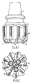
- the body 10 of the drill bit is typically formed of tungsten carbide matrix infiltrated with a binder alloy, and has a threaded shank 11 at one end for connection to the drill string.
- the operative end face 12 of the bit body is formed with a number of blades 13 radiating from the central area of the bit, and the blades carry cutting structures 14 spaced apart along the length thereof.
- the bit has a gauge section including kickers 16 which contact the wall of the bore hole to stabilise the bit in the bore hole.
- a central passage (not shown) in the bit body and shank delivers drilling fluid through nozzles 17 in the end face 12 in known manner to clean and/or cool the cutting elements.
- each cutting structure 14 comprises a preform cutting element mounted on a carrier in the form of a stud which is located in a socket in the bit body.
- each preform cutting element is usually circular and comprises a thin facing layer of polycrystalline diamond bonded to a backing layer of tungsten carbide.
- this is only one example of the many possible variations of trie type of bit to which the invention is applicable, including bits where each preform cutting element comprises a unitary layer of thermally stable polycrystalline diamond material.
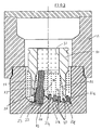
- Figure 3 illustrates a method of manufacturing a bit body of the kind shown in Figures 1 and 2.
- a two part mould 19 is formed from graphite and has an internal configuration corresponding generally to the required surface shape of the bit body or a portion thereof.
- the mould may be formed with elongate recesses corresponding to the blades 13.
- Spaced apart along each blade- forming recess are a plurality of sockets 20 each of which receives a cylindrical former 21a - 21e, the object of the formers being to define in the matrix sockets to receive the studs on which the cutting elements are mounted.
- the formers are of the same cross-sectional shape as the studs, for example circular (as shown) or rectangular.
- the formers and studs may be tapered. The detailed construction of the formers will be described below.
- the matrix material is moulded on and within a hollow steel blank 30.
- the blank is supported in the mould 19 so that its outer surface is spaced from the inner surface of the mould.
- the blank has an upper cylindrical internal cavity 31 communicating with a lower diverging cavity 32.
- the former 23 comprises a first generally cylindrical portion 24, a second cylindrical portion 25 formed with an external screw thread 26, a third conically tapering portion 27 and a fourth elongate portion 28 of smaller diameter.
- the bottom of the mould and the projecting part of the portion 24 of the former 23 may have applied thereto a layer of hard matrix-forming material to form a hard facing for the end face of the drill bit, and the cylindrical mouth of the nozzle socket.
- the steel blank 30 is inserted into the mould and supported with its outer surface spaced from the inner surfaces of the mould.
- Powdered matrix forming material for example, powdered tungsten carbide
- Tungsten metal powder is then packed in the upper cavity 32 in the steel blank 30.
- the matrix forming material is then infiltrated with a suitable binder alloy in a furnace to form the matrix, in known manner.
- the formers 21 and 23 are removed from the bit body and the sockets so formed are then ready to receive the cutting structures 14 and nozzles 17 respectively.
- the formers 21 and 23 have conventionally been formed from graphite with the consequent disadvantages referred to earlier. According to the present invention, however, some or all of the formers are formed from material having a coefficient of thermal expansion not less than that of the matrix material. Each such former is also preferably formed, at least at the outer surf ace thereof, of material which does not wet, or react with, the binder alloy used to infiltrate the matrix material.
- the formers may be formed from austenitic stainless steel which has a coefficient of thermal expansion significantly greater than that of the matrix.
- the formers unlike graphite formers, are not subjected to substantial compressive stresses and, being formed from a material of greater dimensional stability than graphite, are not deformed to an extent as to cause serious variations in the dimensions of the sockets.
- each former may comprise a main body of stainless steel having a surface coating either in the form of a release agent, such as boron nitride, or in the form of a plated layer such as bronze or titanium nitride.
- a release agent such as boron nitride
- a plated layer such as bronze or titanium nitride.
- Each former may be provided with means to facilitate its remowal from the finished bit body after infiltration.
- the nozzle former 24 may be provided with an integral projecting rectangular end boss 33 for engagement by a spanner to permit the former 24 to be unscrewed from the bit body.
- the former 21a is formed with an internally threaded blind bore into which a threaded portion of an extractor tool may be inserted and, similarly, the former 21c is provided with an internally threaded bore passing completely through the former.
- the former 21e is formed with a projecting externally threaded boss for engagement by an internal thread on an extracting tool.
- the former 21d is shown as an example of a former which tapers towards the interior of the mould space so as to produce a socket for engagement by a similarly tapered stud carrying a cutting element.
- the advantages that this may provide have been referred to earlier.
Landscapes
- Engineering & Computer Science (AREA)
- Mechanical Engineering (AREA)
- Life Sciences & Earth Sciences (AREA)
- Manufacturing & Machinery (AREA)
- Mining & Mineral Resources (AREA)
- Geology (AREA)
- Environmental & Geological Engineering (AREA)
- Physics & Mathematics (AREA)
- Materials Engineering (AREA)
- Fluid Mechanics (AREA)
- Composite Materials (AREA)
- Chemical & Material Sciences (AREA)
- General Life Sciences & Earth Sciences (AREA)
- Geochemistry & Mineralogy (AREA)
- Earth Drilling (AREA)
- Drilling Tools (AREA)
- Signal Processing For Digital Recording And Reproducing (AREA)
- Manufacturing Of Electric Cables (AREA)
- Saccharide Compounds (AREA)
Claims (16)
Applications Claiming Priority (2)
| Application Number | Priority Date | Filing Date | Title |
|---|---|---|---|
| GB8510494 | 1985-04-25 | ||
| GB858510494A GB8510494D0 (en) | 1985-04-25 | 1985-04-25 | Rotary drill bits |
Publications (2)
| Publication Number | Publication Date |
|---|---|
| EP0200476A1 EP0200476A1 (de) | 1986-11-05 |
| EP0200476B1 true EP0200476B1 (de) | 1989-08-02 |
Family
ID=10578164
Family Applications (1)
| Application Number | Title | Priority Date | Filing Date |
|---|---|---|---|
| EP86303088A Expired EP0200476B1 (de) | 1985-04-25 | 1986-04-24 | Drehbohrmeissel |
Country Status (6)
| Country | Link |
|---|---|
| US (1) | US4720371A (de) |
| EP (1) | EP0200476B1 (de) |
| CA (1) | CA1254772A (de) |
| DE (1) | DE3664799D1 (de) |
| GB (1) | GB8510494D0 (de) |
| NO (1) | NO861586L (de) |
Families Citing this family (18)
| Publication number | Priority date | Publication date | Assignee | Title |
|---|---|---|---|---|
| US4780274A (en) * | 1983-12-03 | 1988-10-25 | Reed Tool Company, Ltd. | Manufacture of rotary drill bits |
| US5090491A (en) * | 1987-10-13 | 1992-02-25 | Eastman Christensen Company | Earth boring drill bit with matrix displacing material |
| US4884477A (en) * | 1988-03-31 | 1989-12-05 | Eastman Christensen Company | Rotary drill bit with abrasion and erosion resistant facing |
| US4834938A (en) * | 1988-04-25 | 1989-05-30 | The Dow Chemical Company | Method for making composite articles that include complex internal geometry |
| US4919013A (en) * | 1988-09-14 | 1990-04-24 | Eastman Christensen Company | Preformed elements for a rotary drill bit |
| US5033559A (en) * | 1990-05-11 | 1991-07-23 | Dresser Industries, Inc. | Drill bit with faceted profile |
| US5373907A (en) * | 1993-01-26 | 1994-12-20 | Dresser Industries, Inc. | Method and apparatus for manufacturing and inspecting the quality of a matrix body drill bit |
| US5615747A (en) * | 1994-09-07 | 1997-04-01 | Vail, Iii; William B. | Monolithic self sharpening rotary drill bit having tungsten carbide rods cast in steel alloys |
| US6962217B1 (en) * | 1994-09-07 | 2005-11-08 | Smart Drilling And Completion, Inc. | Rotary drill bit compensating for changes in hardness of geological formations |
| GB9603402D0 (en) * | 1996-02-17 | 1996-04-17 | Camco Drilling Group Ltd | Improvements in or relating to rotary drill bits |
| US9199315B2 (en) | 2000-06-02 | 2015-12-01 | Kennametal Inc. | Twist drill and method for producing a twist drill which method includes forming a flute of a twist drill |
| KR100437683B1 (ko) * | 2001-12-18 | 2004-06-30 | 전언찬 | 마이크로 밀링커터의 모서리 제조방법 |
| US7625521B2 (en) | 2003-06-05 | 2009-12-01 | Smith International, Inc. | Bonding of cutters in drill bits |
| US20040245024A1 (en) * | 2003-06-05 | 2004-12-09 | Kembaiyan Kumar T. | Bit body formed of multiple matrix materials and method for making the same |
| DE102010017059A1 (de) * | 2010-05-21 | 2011-11-24 | Kennametal Sintec Keramik Gmbh | Verfahren zur Herstellung eines Bohrkopf-Hauptkörpers |
| WO2012177252A1 (en) | 2011-06-22 | 2012-12-27 | Halliburton Energy Services, Inc. | Custom shaped blank |
| CN107635699A (zh) | 2015-06-23 | 2018-01-26 | 哈里伯顿能源服务公司 | 用以提供的增强金属组分和复合组分之间的粘合力的预扩散心轴涂层 |
| US11512537B2 (en) * | 2020-02-05 | 2022-11-29 | Baker Hughes Oilfield Operations Llc | Displacement members comprising machineable material portions, bit bodies comprising machineable material portions from such displacement members, earth-boring rotary drill bits comprising such bit bodies, and related methods |
Family Cites Families (9)
| Publication number | Priority date | Publication date | Assignee | Title |
|---|---|---|---|---|
| US2941288A (en) * | 1957-01-28 | 1960-06-21 | Republic Steel Corp | Process of making non-galling threaded titanium members |
| GB1137053A (en) * | 1966-01-06 | 1968-12-18 | Shell Int Research | Method and apparatus for manufacturing sintered diamond drilling bit |
| US3818521A (en) * | 1972-03-13 | 1974-06-25 | Richards Quality Bedding Co | Mattress cover construction |
| US3992202A (en) * | 1974-10-11 | 1976-11-16 | Crucible Inc. | Method for producing aperture-containing powder-metallurgy article |
| US4214906A (en) * | 1974-11-29 | 1980-07-29 | Volkswagenwerk Aktiengesellschaft | Method of producing an article which comprises a first zone of a nonoxide ceramic material and a second zone of a softer material |
| DE2742816C3 (de) * | 1977-09-23 | 1980-10-16 | Mtu Motoren- Und Turbinen-Union Muenchen Gmbh, 8000 Muenchen | Verfahren zur Herstellung von Silizium-Keramik-Bauteilen |
| US4145798A (en) * | 1977-10-21 | 1979-03-27 | Federal-Mogul Corporation | Forging recessed configurations on a body member |
| US4378247A (en) * | 1979-05-23 | 1983-03-29 | Permacor Altair, Inc. | Method of making sintered powdered aluminum inductor cores |
| US4453605A (en) * | 1981-04-30 | 1984-06-12 | Nl Industries, Inc. | Drill bit and method of metallurgical and mechanical holding of cutters in a drill bit |
-
1985
- 1985-04-25 GB GB858510494A patent/GB8510494D0/en active Pending
-
1986
- 1986-04-21 US US06/854,178 patent/US4720371A/en not_active Expired - Fee Related
- 1986-04-23 NO NO861586A patent/NO861586L/no unknown
- 1986-04-24 DE DE8686303088T patent/DE3664799D1/de not_active Expired
- 1986-04-24 EP EP86303088A patent/EP0200476B1/de not_active Expired
- 1986-04-25 CA CA000507678A patent/CA1254772A/en not_active Expired
Also Published As
| Publication number | Publication date |
|---|---|
| GB8510494D0 (en) | 1985-05-30 |
| NO861586L (no) | 1986-10-27 |
| EP0200476A1 (de) | 1986-11-05 |
| CA1254772A (en) | 1989-05-30 |
| DE3664799D1 (en) | 1989-09-07 |
| US4720371A (en) | 1988-01-19 |
Similar Documents
| Publication | Publication Date | Title |
|---|---|---|
| EP0200476B1 (de) | Drehbohrmeissel | |
| EP0198627B1 (de) | Herstellung von Drehbohrmeisseln | |
| US4694919A (en) | Rotary drill bits with nozzle former and method of manufacturing | |
| EP0733776B1 (de) | Drehbohr-Fräsmeissel mit Kalibereinsätzen aus polykristallinem Diamant | |
| EP0643792B1 (de) | Kegelrollenmeissel mit verschleissfesten schneideinsätzen | |
| US5732783A (en) | In or relating to rotary drill bits | |
| US4667756A (en) | Matrix bit with extended blades | |
| US5373907A (en) | Method and apparatus for manufacturing and inspecting the quality of a matrix body drill bit | |
| EP0144222B1 (de) | Drehbohrwerkzeug | |
| EP0315330B1 (de) | Herstellung von Rotationsbohrmeisseln | |
| US20140326515A1 (en) | Rotating cutting elements for pdc bits | |
| EP0601840A1 (de) | Verbesserungen an Drehbohrmeisseln | |
| US5033559A (en) | Drill bit with faceted profile | |
| EP0492457A2 (de) | Matrix-Diamant-Fräsmeissel mit zylinderförmigen PCD-Schneidelementen | |
| US4700790A (en) | Rotary drill bits | |
| US4762028A (en) | Rotary drill bits | |
| GB2385814A (en) | Enhanced gage protection for milled tooth rock bits | |
| EP2169178A2 (de) | Matrix-Turbinenhülse und Herstellungsverfahren dafür | |
| US4878403A (en) | Manufacture of rotary drill bits | |
| EP0197741A2 (de) | Drehbohrmeissel und Verfahren zu deren Herstellung | |
| GB2060735A (en) | Improvements in diamond drill bits for drilling bore holes in earth formations | |
| GB2318993A (en) | Improvements in or relating to rotary drill bits | |
| EP0242999A2 (de) | Schneidstrukturen für drehende Bohrköpfe | |
| CA1116161A (en) | Drill bits embodying diamond impregnated segments | |
| EP2899360B1 (de) | Verfahren zur Reduzierung intermetallischer Verbindungen in einer Matrixbit-Klebeschicht |
Legal Events
| Date | Code | Title | Description |
|---|---|---|---|
| PUAI | Public reference made under article 153(3) epc to a published international application that has entered the european phase |
Free format text: ORIGINAL CODE: 0009012 |
|
| AK | Designated contracting states |
Kind code of ref document: A1 Designated state(s): BE CH DE FR GB LI NL SE |
|
| 17P | Request for examination filed |
Effective date: 19861223 |
|
| 17Q | First examination report despatched |
Effective date: 19880323 |
|
| RAP1 | Party data changed (applicant data changed or rights of an application transferred) |
Owner name: REED TOOL COMPANY LIMITED |
|
| GRAA | (expected) grant |
Free format text: ORIGINAL CODE: 0009210 |
|
| AK | Designated contracting states |
Kind code of ref document: B1 Designated state(s): BE CH DE FR GB LI NL SE |
|
| PG25 | Lapsed in a contracting state [announced via postgrant information from national office to epo] |
Ref country code: SE Effective date: 19890802 Ref country code: LI Effective date: 19890802 Ref country code: CH Effective date: 19890802 |
|
| REF | Corresponds to: |
Ref document number: 3664799 Country of ref document: DE Date of ref document: 19890907 |
|
| ET | Fr: translation filed | ||
| REG | Reference to a national code |
Ref country code: CH Ref legal event code: PL |
|
| PLBE | No opposition filed within time limit |
Free format text: ORIGINAL CODE: 0009261 |
|
| STAA | Information on the status of an ep patent application or granted ep patent |
Free format text: STATUS: NO OPPOSITION FILED WITHIN TIME LIMIT |
|
| 26N | No opposition filed | ||
| PGFP | Annual fee paid to national office [announced via postgrant information from national office to epo] |
Ref country code: GB Payment date: 19910415 Year of fee payment: 6 |
|
| PGFP | Annual fee paid to national office [announced via postgrant information from national office to epo] |
Ref country code: FR Payment date: 19910426 Year of fee payment: 6 |
|
| PGFP | Annual fee paid to national office [announced via postgrant information from national office to epo] |
Ref country code: NL Payment date: 19910430 Year of fee payment: 6 |
|
| PGFP | Annual fee paid to national office [announced via postgrant information from national office to epo] |
Ref country code: DE Payment date: 19910531 Year of fee payment: 6 |
|
| PGFP | Annual fee paid to national office [announced via postgrant information from national office to epo] |
Ref country code: BE Payment date: 19910603 Year of fee payment: 6 |
|
| PG25 | Lapsed in a contracting state [announced via postgrant information from national office to epo] |
Ref country code: GB Effective date: 19920424 |
|
| PG25 | Lapsed in a contracting state [announced via postgrant information from national office to epo] |
Ref country code: BE Effective date: 19920430 |
|
| BERE | Be: lapsed |
Owner name: REED TOOL CY LTD Effective date: 19920430 |
|
| PG25 | Lapsed in a contracting state [announced via postgrant information from national office to epo] |
Ref country code: NL Effective date: 19921101 |
|
| NLV4 | Nl: lapsed or anulled due to non-payment of the annual fee | ||
| GBPC | Gb: european patent ceased through non-payment of renewal fee | ||
| PG25 | Lapsed in a contracting state [announced via postgrant information from national office to epo] |
Ref country code: FR Effective date: 19921230 |
|
| PG25 | Lapsed in a contracting state [announced via postgrant information from national office to epo] |
Ref country code: DE Effective date: 19930101 |
|
| REG | Reference to a national code |
Ref country code: FR Ref legal event code: ST |