EP0200369A1 - A manipulator - Google Patents
A manipulator Download PDFInfo
- Publication number
- EP0200369A1 EP0200369A1 EP86302383A EP86302383A EP0200369A1 EP 0200369 A1 EP0200369 A1 EP 0200369A1 EP 86302383 A EP86302383 A EP 86302383A EP 86302383 A EP86302383 A EP 86302383A EP 0200369 A1 EP0200369 A1 EP 0200369A1
- Authority
- EP
- European Patent Office
- Prior art keywords
- arm
- end effector
- arms
- supporting structure
- mounting
- Prior art date
- Legal status (The legal status is an assumption and is not a legal conclusion. Google has not performed a legal analysis and makes no representation as to the accuracy of the status listed.)
- Withdrawn
Links
- 239000012636 effector Substances 0.000 claims abstract description 42
- 238000006073 displacement reaction Methods 0.000 claims description 3
- 230000007246 mechanism Effects 0.000 description 6
- 238000010276 construction Methods 0.000 description 4
- 210000000707 wrist Anatomy 0.000 description 2
- 238000005452 bending Methods 0.000 description 1
Images

Classifications
-
- B—PERFORMING OPERATIONS; TRANSPORTING
- B25—HAND TOOLS; PORTABLE POWER-DRIVEN TOOLS; MANIPULATORS
- B25J—MANIPULATORS; CHAMBERS PROVIDED WITH MANIPULATION DEVICES
- B25J17/00—Joints
- B25J17/02—Wrist joints
- B25J17/0258—Two-dimensional joints
- B25J17/0275—Universal joints, e.g. Hooke, Cardan, ball joints
-
- B—PERFORMING OPERATIONS; TRANSPORTING
- B25—HAND TOOLS; PORTABLE POWER-DRIVEN TOOLS; MANIPULATORS
- B25J—MANIPULATORS; CHAMBERS PROVIDED WITH MANIPULATION DEVICES
- B25J17/00—Joints
- B25J17/02—Wrist joints
- B25J17/0258—Two-dimensional joints
- B25J17/0266—Two-dimensional joints comprising more than two actuating or connecting rods
Definitions
- This invention relates to a manipulator for controlling the position of what is referred to as an "end effector"; which term covers such things as tools, gripping devices and holding devices.
- the invention concerns the type of manipulator which includes at least three arms each connecting the end effector to a fixed point on a supporting structure. In such a construction the effective length of each arm is adjusted to position the end effectcr as required.
- manipulator of the aforementioned type is described in our U.K. Patent Specification No: 2083795.
- This system is able to manipulate an end effector to any desired point in a volume of space and also to orientate it at a desired orientation at that point.
- the manipulator includes six, instead of three, control arms.
- the problem with this arrangment is that it is relatively complex and that the degree of adjustment of orientation of the end effector, for any particular position of it in the aforementioned volume of space, is limited.
- This invention provides a manipulator having three arms of variable effective length connecting fixed points on a supporting structure to an end effector mounting characterised in that the three arms are connected to different points on the mounting for rotation about respective axes fixed with respect to the mounting and the three axes intersect at a common point, and means are provided for varying the effective length of the three arms by sliding them through the said fixed points along axes passing through said common point.
- Each arm is preferably connected to the mounting by a pivot which allows rotation about only one fixed axis. This makes for a more rigid and relatively simple construction.
- the end effector mounting includes a fourth arm, which is preferably straight, and which joins the end effector to the supporting structure by connections which allow the fourth arm to pivot about two intersecting orthogonal axes perpendicular to its length and to slide longitudinally relative to the frame.
- a fourth arm which is preferably straight, and which joins the end effector to the supporting structure by connections which allow the fourth arm to pivot about two intersecting orthogonal axes perpendicular to its length and to slide longitudinally relative to the frame.
- the provision of the fourth arm is considered to be a useful and novel feature in itself applicable tc other systems, for example to systems with a complex pivot arrangement like that described in U.S. Patent Specification No. 4407625.
- a problem with this design of manipulator is that the arm jointing is complex and the end effector is displaced from the point at which the arms intersect, so it requires a complex control system to calculate the relationship between the positions of one or more of the arms and the position of the end effector.
- a manipulator having at least three arms, some of which are of variable effective length, connecting points on a supporting structure to an end effector mounting; and an extra arm joining the end effector mounting to the supporting structure, the extra arm being able to pivot and to slide longitudinally relative to the supporting structure.
- the extra arm is preferably straight and is adapted to be attached directly to the end effector.
- the position of the end effector may then be calculated from the angles of rotation and the longitudinal displacement of the fourth arm.
- the end effector may be held more rigidly than would be possible without the fourth arm.
- Each drive mechanism 2 is pivotted about an axis II to a bifurcated support 5.
- the later is pivotted about an axis III to a supporting structure 6.
- Each associated group of axes I, II and III are orthogonal to each other, although this is not essential, it is sufficient for axes I and II to be orthogonal and axes II and III to be orthogonal, and axes I, II and III intersect at a common point.
- Each arm 1 has a double bend which offsets its lower end from its axis I cf longitudinal movement. This offset lower end is pivotted about an axis IV to respective positions spaced around a ring 7 forming part of an end effector support (formed by components 7-14).
- the axes IV are symmetrically arranged in a plane (which is horizontal in the position illustrated) and they intersect at a common point in that plane.
- the end effector support comprises a mounting plate 8 which is attached to the fourth arm 11.
- the parts 7 and 8 are replaced by a single rigid mounting bracket to which the end effector is attached; and no further components are needed since the longitudinal position of adjustment of the three arms can be used to move the end effector to any desired position within a space between the legs of the supporting structure.
- the orientation of the end effector support may be difficult to calculate and this information will be needed in some circumstances e.g., when the end effector includes a wrist mechanism.
- the preferred features now to be described help to overcome these problems.
- the end effector support also includes a ring 9 (see Figure 2) which is pivotted to the ring 7 about an axis V and to an inner bush 10 about an axis VI.
- Axes V and VI intersect at the same point, and this point is the same as that at which axes I and IV intersect.
- the bush 10 has a central bore which receives a reduced diameter portion at the lower end of a fourth arm 11 in such a way as to allow the bush 10 to rotate relative to the arm 11.
- the fourth arm 11 is connected to a fixed point on the supporting structure 6 by a gimbal mechanism shown in detail in Figure 3 and comprising an inner ring 13 pivotted to a second ring 12 about an axis IX, the ring 12 being pivotted to the supporting structure 6 about an axis IIX, the fourth arm 11 is also rigidly connected at its lower end to the bracket 8.
- the axes VII, IIX and IX are orthogonal to each other, although this is not essential, it is sufficient for axes VII and IX to be orthogonal and for axes IIX and IX to be orthogonal, and axes VII, IIX and IX intersect at a common point.
- the fourth arm 11 is able to slide longitudinally in the direction of axis VII through an inner ring 13. It has a slot 14 which receives an inwardly pointing prcjection on the ring 13 to key it against axial rotation about axis VII relative to the supporting structure 6. Operation of the motors 5 control the effective lengths of the arms 1.
- the effective lengths are the distances between the points where axes I, II and III intersect and the point where axes IV and I intersect.
- the choice of appropriate effective lengths of the arms 1 uniquely defines the position in space of the last mentioned point which is the effective point at which the end effector is mounted.
- the end effector is constrained by the fourth arm 11 always to be the line adjoining the last mentioned point to the fixed point on the supporting frame 6 where axes VIII and IX intersect.
- Suitable sensors not shown produce signals on lines 15 and 16 representing the degree of rotation of the arm 11 about axes IIX and IX respectively whilst a linear position encoder 17 produces a signal on line 18 representing its position along the axis VII.
- This information completely defines the position of the end effector and is compared in a control circuit 19 with the desired position entered at 19 to prcduce correction signals on lines 20, 21 and 22 to operate the motors 3 in directions such as to reduce the difference between the real and required positions.
Landscapes
- Engineering & Computer Science (AREA)
- Robotics (AREA)
- Mechanical Engineering (AREA)
- Manipulator (AREA)
Abstract
A manipulator comprises three arms 1 which can pivot at different points on a supporting structure 6 and which can be driven longitudinally to adjust their effective lengths. The longitudinal axes of the three arms intersect at a common point but their lower ends are offset from this point and are pivotted about respective axes which also intersect at the aforementioned common point. They are pivotted to an end effector mounting flange 8 which optionally comprises a fourth arm 11 which slides an pivots on the supporting structure. The fourth arm serves to ensure that the flange 8 always faces at a known orientation. It can also be used in co-operation with suitable sensors to produce signals on lines 15,16 and 18to a control unit which drives the arms 1 in their linear directions.
Description
- This invention relates to a manipulator for controlling the position of what is referred to as an "end effector"; which term covers such things as tools, gripping devices and holding devices. The invention concerns the type of manipulator which includes at least three arms each connecting the end effector to a fixed point on a supporting structure. In such a construction the effective length of each arm is adjusted to position the end effectcr as required.
- One known manipulator of the aforementioned type is described in our U.K. Patent Specification No: 2083795. This system is able to manipulate an end effector to any desired point in a volume of space and also to orientate it at a desired orientation at that point. For this purpose the manipulator includes six, instead of three, control arms. The problem with this arrangment is that it is relatively complex and that the degree of adjustment of orientation of the end effector, for any particular position of it in the aforementioned volume of space, is limited.
- Another known manipulator is described with reference to Figure 1 in U.S. Patent Specification No: 4407625. This comprises three arms connected at their bottom ends by a pivot mechanism allowing all three to pivot relative to each other about a common point. The end effector is connected to one of the three arms. A manipulator of this type does not allow orientation of the end effector when it has been moved to a desired point. Such adjustment of orientation is not necessarily a disadvantage since the end effector itself can be provided with a special wrist mechanism providing a freedom for adjustment of orientation through large angles (greater than the angles provided for by the arrangement of U.K. Specification No: 2083795). Also of course some types of end effector, including that shown in U.S. Specification No: 4407625, do not require such adjustment of orientation. A problem however with the arrangement described in the U.S. Specification is that the pivot arrangement at the bottom of arms is relatively complex and that there is no way in which the end effector can be connected directly to the pivot point. This means that, to move the end effector to a given point, it is necessary to take into consideration an offset between the end effector and the pivot point. The need for this complicates the control system.
- This invention provides a manipulator having three arms of variable effective length connecting fixed points on a supporting structure to an end effector mounting characterised in that the three arms are connected to different points on the mounting for rotation about respective axes fixed with respect to the mounting and the three axes intersect at a common point, and means are provided for varying the effective length of the three arms by sliding them through the said fixed points along axes passing through said common point.
- Each arm is preferably connected to the mounting by a pivot which allows rotation about only one fixed axis. This makes for a more rigid and relatively simple construction.
- By employing the invention only three simple pivots are required instead of the complex pivotting arrangement of the aforementioned U.S. Patent Specification. Also, the difficulty of mounting the end effector in the design of the system described in the U.S. Patent Specification Nc: 4407625 is removed. This is because an inherent part of the invention is an end effector mounting member.
- In a preferred form of the invention the end effector mounting includes a fourth arm, which is preferably straight, and which joins the end effector to the supporting structure by connections which allow the fourth arm to pivot about two intersecting orthogonal axes perpendicular to its length and to slide longitudinally relative to the frame. One advantage of this arrangement is that the position of the end effector can"be determined by three sensors which monitor the angles of rotation and the longitudinal displacement of the fourth arm. Furthermore, the end effector is held more rigidly than would be the case without the fourth arm.
- The provision of the fourth arm is considered to be a useful and novel feature in itself applicable tc other systems, for example to systems with a complex pivot arrangement like that described in U.S. Patent Specification No. 4407625. A problem with this design of manipulator is that the arm jointing is complex and the end effector is displaced from the point at which the arms intersect, so it requires a complex control system to calculate the relationship between the positions of one or more of the arms and the position of the end effector. Thus, according to a seccnd aspect of this invention there is provided a manipulator having at least three arms, some of which are of variable effective length, connecting points on a supporting structure to an end effector mounting; and an extra arm joining the end effector mounting to the supporting structure, the extra arm being able to pivot and to slide longitudinally relative to the supporting structure.
- The extra arm is preferably straight and is adapted to be attached directly to the end effector. The position of the end effector may then be calculated from the angles of rotation and the longitudinal displacement of the fourth arm. Furthermore, the end effector may be held more rigidly than would be possible without the fourth arm.
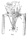
- One way in which the invention may be performed will now be described by way of example with reference to the accompanying drawing of a manipulator constructed in accordance with the invention.
- Referring to the drawing three screw threaded control arms 1 are driven longitudinally in the direction of axes I by drive mechanisms 2 each including a motor 3 and drive 4 cc-operating with the screw thread. Axes I intersect at a common point which will be referred to later.
- Each drive mechanism 2 is pivotted about an axis II to a bifurcated
support 5. The later is pivotted about an axis III to a supportingstructure 6. Each associated group of axes I, II and III are orthogonal to each other, although this is not essential, it is sufficient for axes I and II to be orthogonal and axes II and III to be orthogonal, and axes I, II and III intersect at a common point. - Each arm 1, has a double bend which offsets its lower end from its axis I cf longitudinal movement. This offset lower end is pivotted about an axis IV to respective positions spaced around a
ring 7 forming part of an end effector support (formed by components 7-14). The axes IV are symmetrically arranged in a plane (which is horizontal in the position illustrated) and they intersect at a common point in that plane. - The end effector support comprises a
mounting plate 8 which is attached to thefourth arm 11. In an alternative construction (not shown) theparts - In the illustrated construction the end effector support also includes a ring 9 (see Figure 2) which is pivotted to the
ring 7 about an axis V and to aninner bush 10 about an axis VI. Axes V and VI intersect at the same point, and this point is the same as that at which axes I and IV intersect. Thebush 10 has a central bore which receives a reduced diameter portion at the lower end of afourth arm 11 in such a way as to allow thebush 10 to rotate relative to thearm 11. - This rotation takes place about a longitudinal central axis VII which passes through the same point as that at which the axes I, IV, V and VI intersect. The
fourth arm 11 is connected to a fixed point on the supportingstructure 6 by a gimbal mechanism shown in detail in Figure 3 and comprising aninner ring 13 pivotted to asecond ring 12 about an axis IX, thering 12 being pivotted to the supportingstructure 6 about an axis IIX, thefourth arm 11 is also rigidly connected at its lower end to thebracket 8. The axes VII, IIX and IX are orthogonal to each other, although this is not essential, it is sufficient for axes VII and IX to be orthogonal and for axes IIX and IX to be orthogonal, and axes VII, IIX and IX intersect at a common point. Thefourth arm 11 is able to slide longitudinally in the direction of axis VII through aninner ring 13. It has aslot 14 which receives an inwardly pointing prcjection on thering 13 to key it against axial rotation about axis VII relative to the supportingstructure 6. Operation of themotors 5 control the effective lengths of the arms 1. The effective lengths are the distances between the points where axes I, II and III intersect and the point where axes IV and I intersect. The choice of appropriate effective lengths of the arms 1 uniquely defines the position in space of the last mentioned point which is the effective point at which the end effector is mounted. The orientation of - the end effector is constrained by the
fourth arm 11 always to be the line adjoining the last mentioned point to the fixed point on the supportingframe 6 where axes VIII and IX intersect. - Suitable sensors, not shown produce signals on
lines arm 11 about axes IIX and IX respectively whilst alinear position encoder 17 produces a signal online 18 representing its position along the axis VII. This information completely defines the position of the end effector and is compared in acontrol circuit 19 with the desired position entered at 19 to prcduce correction signals onlines
Claims (8)
1. A manipulator having: three arms connecting fixed points on a supporting structure to an end effector mounting, the three arms being connected to different fixed points on the mounting in a way which allows rotation of the arms relative to the mounting about respective axes which intersect at a common point; and three drive means each acting. on a part of, a corresponding arm so as to drive that part along a straight line passing through the said common point.
2. A manipulator according to claim 1 in which each arm is connected to the mounting by a pivot which allows rotation about only one fixed axis.
3. A manipulator according to any preceding claim in which the counting includes a fourth arm pivotally mounted to a point on the supporting structure.
4. A manipulator according to claim 3 including means for sensing movement and/or position of the fourth arm and for controlling the drives in response.
5. A manipulator having at least three arms, some of which are of variable effective length, connecting points on a supporting structure to an end effector mounting; and an extra arm joining the end effector mounting to the supporting structure, the extra arm being able tc pivot and to slide longitudinally relative to the supporting structure. reference to the accompanying drawing and substantially as described therein.
6. An extra arm as claimed in claim 5 wherein the extra arm is straight.
7. An extra arm as claimed in claim 5 or 6 wherein the end effector is attached directly to the end of the extra arm.
8. An extra arm as claimed in claim 5,6 or 7 wherein the position of the end effector is calculated from the position of the end effector is calculated from the angles of rotation and longitudinal displacement of the extra arm.
Applications Claiming Priority (4)
| Application Number | Priority Date | Filing Date | Title |
|---|---|---|---|
| GB8508387 | 1985-03-27 | ||
| GB858508387A GB8508387D0 (en) | 1985-03-30 | 1985-03-30 | Manipulator |
| GB08509402A GB2173472B (en) | 1985-03-30 | 1985-04-12 | A manipulator |
| GB8509402 | 1985-04-12 |
Publications (1)
| Publication Number | Publication Date |
|---|---|
| EP0200369A1 true EP0200369A1 (en) | 1986-11-05 |
Family
ID=26289069
Family Applications (1)
| Application Number | Title | Priority Date | Filing Date |
|---|---|---|---|
| EP86302383A Withdrawn EP0200369A1 (en) | 1985-03-30 | 1986-04-01 | A manipulator |
Country Status (3)
| Country | Link |
|---|---|
| US (1) | US4790718A (en) |
| EP (1) | EP0200369A1 (en) |
| GB (1) | GB8607936D0 (en) |
Cited By (15)
| Publication number | Priority date | Publication date | Assignee | Title |
|---|---|---|---|---|
| EP0202206B1 (en) * | 1985-05-10 | 1990-03-07 | Neos Products Hb | Robot |
| US5562393A (en) * | 1993-09-06 | 1996-10-08 | Focke & Co. (Gmbh & Co.) | Handling apparatus having a retractable and extendable telescopic part |
| EP0834383A1 (en) * | 1996-10-07 | 1998-04-08 | Gec Alsthom Systemes Et Services Sa | Robot with a parallel structure |
| DE19757133C1 (en) * | 1997-12-20 | 1999-07-29 | Juergen Prof Dr Ing Hesselbach | Tool positioning device with parallel structure for orienting final effector with at least three degrees of freedom |
| ES2195735A1 (en) * | 2001-07-23 | 2003-12-01 | Gamesa Desarrollos Aeronauticos Sa | Portable boring machine for mechanising the landing gear support. |
| DE102008023069A1 (en) * | 2008-05-09 | 2009-11-12 | Multivac Sepp Haggenmüller Gmbh & Co. Kg | Handling device i.e. delta robot, for positioning products, has connection element arranged between gripper and suction devices and extended in working position by support, where support for connection element comprises joint structure |
| DE102009057585A1 (en) | 2009-12-09 | 2011-06-16 | Multivac Sepp Haggenmüller Gmbh & Co. Kg | Robot with calibration position |
| US8047093B2 (en) | 2009-01-29 | 2011-11-01 | Fanuc Ltd | Parallel robot |
| CN102320041A (en) * | 2011-08-17 | 2012-01-18 | 中国农业大学 | Three freedom degree series-parallel mechanical arm |
| CN102490177A (en) * | 2011-12-13 | 2012-06-13 | 天津大学 | Four-freedom-degree parallel-connection robot |
| CN102699900A (en) * | 2012-06-06 | 2012-10-03 | 天津大学 | Over-constraint hybrid robot with double platforms and five degrees of freedom |
| CN102873686A (en) * | 2011-07-15 | 2013-01-16 | 株式会社安川电机 | Parallel link robot and picking system |
| CN103009378A (en) * | 2012-12-13 | 2013-04-03 | 大连理工计算机控制工程有限公司 | High-speed parallel-connection robot pickup device with vision |
| CN103085059A (en) * | 2012-12-26 | 2013-05-08 | 燕山大学 | Five-degree-freedom parallel robot with one rotating drive branch and four moving drive branches |
| WO2017005015A1 (en) * | 2015-07-09 | 2017-01-12 | 天津大学 | Five-degree-of-freedom parallel robot with multi-shaft rotary brackets |
Families Citing this family (46)
| Publication number | Priority date | Publication date | Assignee | Title |
|---|---|---|---|---|
| US4919382A (en) * | 1988-09-14 | 1990-04-24 | The United States Of America As Represented By The Secretary Of The Navy | Multi-post yoke gimbal |
| FR2646023B1 (en) * | 1989-04-18 | 1991-06-14 | Europ Agence Spatiale | ANTENNA POINTING DEVICE, SATELLITE PROVIDED WITH SUCH A DEVICE AND ANTENNA POINTING METHOD USING SUCH A DEVICE |
| US5333514A (en) * | 1992-04-24 | 1994-08-02 | Toyoda Koki Kabushiki Kaisha | Parallel robot |
| US5813287A (en) * | 1994-03-02 | 1998-09-29 | Renishaw Plc | Coordinate positioning machine |
| US5740699A (en) * | 1995-04-06 | 1998-04-21 | Spar Aerospace Limited | Wrist joint which is longitudinally extendible |
| US5771747A (en) * | 1996-09-03 | 1998-06-30 | Sheldon/Van Someren, Inc. | Machine having an adjustable framework and an internal multi-axis manipulator |
| US6047610A (en) * | 1997-04-18 | 2000-04-11 | Stocco; Leo J | Hybrid serial/parallel manipulator |
| DE19757885A1 (en) * | 1997-12-24 | 1999-07-08 | Wissner Rolf | Device for positioning a first machine part relative to a second machine part |
| SE512338C2 (en) * | 1998-06-25 | 2000-02-28 | Neos Robotics Ab | System and method for controlling a robot |
| US6587802B1 (en) | 1998-09-17 | 2003-07-01 | Dr. Johannes Heidenhain Gmbh | Calibration device for a parallel kinematic manipulator |
| DE19903613C1 (en) * | 1999-01-29 | 2000-12-07 | Fraunhofer Ges Forschung | Tripod bearing device and method for torsion compensation |
| US7337691B2 (en) * | 1999-08-05 | 2008-03-04 | Shambhu Nath Roy | Parallel kinematics mechanism with a concentric spherical joint |
| US6497548B1 (en) | 1999-08-05 | 2002-12-24 | Shambhu Nath Roy | Parallel kinematics mechanism with a concentric sperical joint |
| US20040013509A1 (en) * | 1999-08-05 | 2004-01-22 | Roy Shambhu Nath | Parallel kinematics mechanism with a concentric spherical joint |
| KR100334902B1 (en) * | 1999-12-06 | 2002-05-04 | 윤덕용 | 6 Degree-of-freedom Parallel Mechanism for Micro-positioning Task |
| JP4632560B2 (en) * | 2000-03-01 | 2011-02-16 | シーグ パック システムズ アクチェンゲゼルシャフト | Robots that operate products in a three-dimensional space |
| NL1015816C2 (en) * | 2000-07-27 | 2002-01-29 | R P T Weekers Holding B V | Manipulator or industrial robot has column fixed to floor and at upper side column is connected with extending part, which can hinge around horizontal axis, for which two bearing parts are fixed to column |
| RU2209718C2 (en) * | 2001-01-09 | 2003-08-10 | Институт автоматики и процессов управления ДВО РАН | Device for control of underwater robot propulsor |
| ES2205970B1 (en) * | 2001-05-10 | 2005-07-16 | Fundacion Fatronik | CINEMATIC SYSTEM FOR MACHINE HEAD. |
| US6671975B2 (en) | 2001-12-10 | 2004-01-06 | C. William Hennessey | Parallel kinematic micromanipulator |
| RU2209719C1 (en) * | 2002-01-25 | 2003-08-10 | Дальневосточный государственный технический университет | Device for control of robot drive |
| US6865011B2 (en) * | 2002-07-30 | 2005-03-08 | The University Of British Columbia | Self-stabilized electrophoretically frustrated total internal reflection display |
| RU2215318C1 (en) * | 2002-08-19 | 2003-10-27 | Институт автоматики и процессов управления Дальневосточного отделения РАН | Variable-structure adaptive system for controlling motion speed of submerged robot |
| CN100446940C (en) * | 2003-09-16 | 2008-12-31 | 天津大学 | Asymmetric space 5 degrees of freedom hybrid robot |
| JP4080992B2 (en) * | 2003-12-25 | 2008-04-23 | オークマ株式会社 | Control method and control device for parallel mechanism machine |
| SE527992C2 (en) * | 2004-12-09 | 2006-08-01 | Exechon Ab | Parallel kinematic machine with active measurement system |
| US20060241810A1 (en) * | 2005-04-20 | 2006-10-26 | Dan Zhang | High stiffness, high accuracy, parallel kinematic, three degree of freedom motion platform |
| CN100348375C (en) * | 2005-07-11 | 2007-11-14 | 天津大学 | Robot with five degrees of freedom |
| CN100348386C (en) * | 2005-09-15 | 2007-11-14 | 天津大学 | Multi-coordinate serioparallel robot with redundant freedom |
| US7673384B2 (en) * | 2006-04-27 | 2010-03-09 | Genesis Systems Group, Llc | Nut runner and hexabot robot |
| CN100480003C (en) * | 2007-04-20 | 2009-04-22 | 天津大学 | Series parallel robot in five degrees of freedom |
| DE102008019965B4 (en) | 2008-04-21 | 2014-08-21 | Schneider Electric Automation Gmbh | Delta robot with turntable in the parallel plate |
| DE102008058644A1 (en) * | 2008-10-10 | 2010-04-15 | Num Industry Alliance Ag | cutter |
| US8215199B2 (en) * | 2008-11-17 | 2012-07-10 | Marcroft Sacha L | Parallel kinematic positioning system |
| US8498741B2 (en) * | 2009-09-22 | 2013-07-30 | Gm Global Technology Operations | Dexterous humanoid robotic wrist |
| CN102049786A (en) * | 2009-11-05 | 2011-05-11 | 鸿富锦精密工业(深圳)有限公司 | Rotating mechanism and robot with same |
| EP2576154A4 (en) * | 2010-05-25 | 2014-09-10 | Systemantics India Pvt Ltd | A hybrid serial-parallel linkage based six degrees of freedom robotic manipulator |
| US8336420B2 (en) * | 2010-06-02 | 2012-12-25 | Disney Enterprises, Inc. | Three-axis robotic joint using four-bar linkages to drive differential side gears |
| US9339945B2 (en) * | 2011-09-19 | 2016-05-17 | California Institute Of Technology | Systems and methods for gravity-independent gripping and drilling |
| CN102581848B (en) * | 2012-03-21 | 2014-04-30 | 天津大学 | Parallel positioning platform with three-rotation one-translation freedom degree |
| CN102615644B (en) * | 2012-03-29 | 2014-06-11 | 天津大学 | Novel posture adjustment mechanism capable of achieving three-rotation one-translation degree of freedom |
| CN102699898B (en) * | 2012-06-06 | 2015-04-29 | 天津大学 | Five-degree-of-freedom over-constrained hybrid robot |
| CN103252771B (en) * | 2013-05-07 | 2015-04-15 | 天津大学 | Asymmetrical five-degree-of-freedom parallel serial robot |
| US9645601B2 (en) * | 2015-04-27 | 2017-05-09 | Robert L. Stevenson | Point of control remote-actuation apparatus and methods |
| CA2933317C (en) * | 2015-06-17 | 2022-03-01 | Montgomery William Childs | Manipulator for movement of articles in a controlled environment chamber |
| CN107671845B (en) * | 2017-11-10 | 2020-07-28 | 燕山大学 | A Few-joint Overconstrained Five-DoF Hybrid Robot |
Citations (3)
| Publication number | Priority date | Publication date | Assignee | Title |
|---|---|---|---|---|
| US3779400A (en) * | 1972-02-14 | 1973-12-18 | Univ Iowa State Res Found Inc | Micromanipulator system |
| GB2085399A (en) * | 1980-10-06 | 1982-04-28 | Simunovic Sergio N | Robotic manipulator |
| GB2143498A (en) * | 1983-07-21 | 1985-02-13 | Emi Ltd | Improvements in or relating to assembly robots |
Family Cites Families (8)
| Publication number | Priority date | Publication date | Assignee | Title |
|---|---|---|---|---|
| US3559936A (en) * | 1968-11-26 | 1971-02-02 | Singer General Precision | Motion simulator |
| SU422580A2 (en) * | 1972-05-04 | 1974-04-05 | В. Д. Абезгауз | MECHANISM OF THE HINGE OF MANIPULATORS P TB |
| US4362977A (en) * | 1980-06-30 | 1982-12-07 | International Business Machines Corporation | Method and apparatus for calibrating a robot to compensate for inaccuracy of the robot |
| GB2083795B (en) * | 1980-09-13 | 1984-01-25 | Marconi Co Ltd | Manipulator mechanisms |
| US4407625A (en) * | 1981-05-15 | 1983-10-04 | Westinghouse Electric Corp. | Multi-arm robot |
| SU1083017A1 (en) * | 1982-04-26 | 1984-03-30 | Институт Машиноведения Им.А.А.Благонравова | Spatial mechanism having six degrees of freedom |
| US4435116A (en) * | 1982-05-27 | 1984-03-06 | Deberg Walter H | Robotic manipulator |
| US4569627A (en) * | 1983-03-10 | 1986-02-11 | Simunovic Sergio N | Robotic manipulator |
-
1986
- 1986-03-27 US US06/844,564 patent/US4790718A/en not_active Expired - Fee Related
- 1986-04-01 EP EP86302383A patent/EP0200369A1/en not_active Withdrawn
- 1986-04-01 GB GB868607936A patent/GB8607936D0/en active Pending
Patent Citations (3)
| Publication number | Priority date | Publication date | Assignee | Title |
|---|---|---|---|---|
| US3779400A (en) * | 1972-02-14 | 1973-12-18 | Univ Iowa State Res Found Inc | Micromanipulator system |
| GB2085399A (en) * | 1980-10-06 | 1982-04-28 | Simunovic Sergio N | Robotic manipulator |
| GB2143498A (en) * | 1983-07-21 | 1985-02-13 | Emi Ltd | Improvements in or relating to assembly robots |
Cited By (27)
| Publication number | Priority date | Publication date | Assignee | Title |
|---|---|---|---|---|
| EP0202206B1 (en) * | 1985-05-10 | 1990-03-07 | Neos Products Hb | Robot |
| US5562393A (en) * | 1993-09-06 | 1996-10-08 | Focke & Co. (Gmbh & Co.) | Handling apparatus having a retractable and extendable telescopic part |
| EP0834383A1 (en) * | 1996-10-07 | 1998-04-08 | Gec Alsthom Systemes Et Services Sa | Robot with a parallel structure |
| FR2754205A1 (en) * | 1996-10-07 | 1998-04-10 | Gec Alsthom Syst Et Serv | ROBOT WITH PARALLEL STRUCTURE |
| DE19757133C1 (en) * | 1997-12-20 | 1999-07-29 | Juergen Prof Dr Ing Hesselbach | Tool positioning device with parallel structure for orienting final effector with at least three degrees of freedom |
| ES2195735A1 (en) * | 2001-07-23 | 2003-12-01 | Gamesa Desarrollos Aeronauticos Sa | Portable boring machine for mechanising the landing gear support. |
| DE102008023069A1 (en) * | 2008-05-09 | 2009-11-12 | Multivac Sepp Haggenmüller Gmbh & Co. Kg | Handling device i.e. delta robot, for positioning products, has connection element arranged between gripper and suction devices and extended in working position by support, where support for connection element comprises joint structure |
| CN101791797B (en) * | 2009-01-29 | 2012-06-20 | 发那科株式会社 | Parallel robot |
| US8047093B2 (en) | 2009-01-29 | 2011-11-01 | Fanuc Ltd | Parallel robot |
| DE102010006155B4 (en) * | 2009-01-29 | 2018-01-18 | Fanuc Corporation | parallel robot |
| DE102009057585B4 (en) * | 2009-12-09 | 2013-11-28 | Multivac Sepp Haggenmüller Gmbh & Co. Kg | Method for calibrating a robot |
| DE102009057585A1 (en) | 2009-12-09 | 2011-06-16 | Multivac Sepp Haggenmüller Gmbh & Co. Kg | Robot with calibration position |
| EP2359988A1 (en) | 2009-12-09 | 2011-08-24 | Multivac Sepp Haggenmüller GmbH & Co. KG | Robot with calibration position |
| US8899126B2 (en) | 2009-12-09 | 2014-12-02 | Multivac Sepp Haggenmuller Gmbh & Co. Kg | Robot with calibration position |
| CN102873686B (en) * | 2011-07-15 | 2015-10-28 | 株式会社安川电机 | Parallel robot and radio frequency |
| CN102873686A (en) * | 2011-07-15 | 2013-01-16 | 株式会社安川电机 | Parallel link robot and picking system |
| CN102320041B (en) * | 2011-08-17 | 2015-01-28 | 中国农业大学 | Three freedom degree series-parallel mechanical arm |
| CN102320041A (en) * | 2011-08-17 | 2012-01-18 | 中国农业大学 | Three freedom degree series-parallel mechanical arm |
| CN102490177B (en) * | 2011-12-13 | 2014-04-30 | 天津大学 | Four-freedom-degree parallel-connection robot |
| CN102490177A (en) * | 2011-12-13 | 2012-06-13 | 天津大学 | Four-freedom-degree parallel-connection robot |
| CN102699900A (en) * | 2012-06-06 | 2012-10-03 | 天津大学 | Over-constraint hybrid robot with double platforms and five degrees of freedom |
| CN102699900B (en) * | 2012-06-06 | 2015-05-27 | 天津大学 | Over-constraint hybrid robot with double platforms and five degrees of freedom |
| CN103009378A (en) * | 2012-12-13 | 2013-04-03 | 大连理工计算机控制工程有限公司 | High-speed parallel-connection robot pickup device with vision |
| CN103085059A (en) * | 2012-12-26 | 2013-05-08 | 燕山大学 | Five-degree-freedom parallel robot with one rotating drive branch and four moving drive branches |
| CN103085059B (en) * | 2012-12-26 | 2015-04-08 | 燕山大学 | Five-degree-freedom parallel robot with one rotating drive branch and four moving drive branches |
| WO2017005015A1 (en) * | 2015-07-09 | 2017-01-12 | 天津大学 | Five-degree-of-freedom parallel robot with multi-shaft rotary brackets |
| US9943967B2 (en) | 2015-07-09 | 2018-04-17 | Tianjin University | Five-degree-of-freedom hybrid robot with rotational supports |
Also Published As
| Publication number | Publication date |
|---|---|
| GB8607936D0 (en) | 1986-05-08 |
| US4790718A (en) | 1988-12-13 |
Similar Documents
| Publication | Publication Date | Title |
|---|---|---|
| US4790718A (en) | Manipulators | |
| US7337691B2 (en) | Parallel kinematics mechanism with a concentric spherical joint | |
| US4329111A (en) | Mechanical manipulator | |
| US7281447B2 (en) | Articulated mechanism comprising a cable reduction gear for use in a robot arm | |
| US4756655A (en) | Mechanical manipulator | |
| US5847528A (en) | Mechanism for control of position and orientation in three dimensions | |
| US6860169B2 (en) | Manipulation unit | |
| US5673595A (en) | Four degree-of-freedom manipulator | |
| US4595334A (en) | Robotic apparatus with improved positioning accuracy | |
| US7275332B2 (en) | Multi-axis positioning apparatus | |
| EP0066393A2 (en) | Multiarm robot | |
| US7086307B2 (en) | Parallel control arm with two branches | |
| JP2005536703A (en) | Parallel manipulator | |
| EP0084249A2 (en) | Mechanical actuator for an industrial robot | |
| GB2143498A (en) | Improvements in or relating to assembly robots | |
| JPS61502322A (en) | robot manipulator | |
| US20040013509A1 (en) | Parallel kinematics mechanism with a concentric spherical joint | |
| GB2173472A (en) | Manipulator | |
| EP0200202A2 (en) | Wrist mechanism for industrial robot | |
| JPH0246357B2 (en) | ||
| EP0193149B1 (en) | Joint mechanism for manipulators | |
| GB2132981A (en) | Robot arm with split wrist motion | |
| US11420324B2 (en) | Parallel link robot | |
| KR20240129310A (en) | 2-DOF delta root | |
| EP0540197A1 (en) | Actuator assembly of a hand-controller |
Legal Events
| Date | Code | Title | Description |
|---|---|---|---|
| PUAI | Public reference made under article 153(3) epc to a published international application that has entered the european phase |
Free format text: ORIGINAL CODE: 0009012 |
|
| AK | Designated contracting states |
Kind code of ref document: A1 Designated state(s): DE FR IT NL SE |
|
| 17P | Request for examination filed |
Effective date: 19870218 |
|
| 17Q | First examination report despatched |
Effective date: 19880212 |
|
| STAA | Information on the status of an ep patent application or granted ep patent |
Free format text: STATUS: THE APPLICATION IS DEEMED TO BE WITHDRAWN |
|
| 18D | Application deemed to be withdrawn |
Effective date: 19881217 |
|
| RIN1 | Information on inventor provided before grant (corrected) |
Inventor name: VICKERS, MARK GORDON |