EP0200313A1 - Transformateur de puissance sans contact et sans force - Google Patents
Transformateur de puissance sans contact et sans force Download PDFInfo
- Publication number
- EP0200313A1 EP0200313A1 EP19860301815 EP86301815A EP0200313A1 EP 0200313 A1 EP0200313 A1 EP 0200313A1 EP 19860301815 EP19860301815 EP 19860301815 EP 86301815 A EP86301815 A EP 86301815A EP 0200313 A1 EP0200313 A1 EP 0200313A1
- Authority
- EP
- European Patent Office
- Prior art keywords
- winding
- core
- inductive coupler
- predetermined
- coupler according
- Prior art date
- Legal status (The legal status is an assumption and is not a legal conclusion. Google has not performed a legal analysis and makes no representation as to the accuracy of the status listed.)
- Granted
Links
Images


Classifications
-
- H—ELECTRICITY
- H01—ELECTRIC ELEMENTS
- H01F—MAGNETS; INDUCTANCES; TRANSFORMERS; SELECTION OF MATERIALS FOR THEIR MAGNETIC PROPERTIES
- H01F38/00—Adaptations of transformers or inductances for specific applications or functions
- H01F38/14—Inductive couplings
Definitions
- This invention relates generally to inductive coupling and more particularly, to transformers where there is relative motion between the primary and secondary windings and minimal reaction forces therebetween.
- the invention described herein has particular utility in applications where electrical power is coupled from a stationary location to a moving' location with a minimum of interaction between the stationary and movable components.
- the invention is principally applied to transferring power across magnetically suspended interfaces, where small disturbance forces might affect the magnetic control forces, and where motions over as many as six degrees of freedom are required over a limited range.
- the present invention improves over the prior art by providing a non-contacting structure that allows motion over six degrees of freedom, provides insignificant reaction forces with respect to the actual control forces applied to a stabilised structure attached thereto, requires no air gap in the core, and provides high efficiency over the required range of motion.
- the present invention is defined in the appended claims and provides a power transformer having an enclosed magnetic core substantially without air gaps, a primary winding, and a secondary winding disposed within the core in a manner to permit relative motion between the first and second windings.
- the first winding is stationary, whilst the movable second winding is positioned radially with respect to the first winding with substantial directional freedom of motion over a limited range.
- This arrangement provides a substantially constant flux coupling between the two windings over the range of motion of the secondary.
- support members are fixed to the secondary winding for supporting a movable structure
- the core is comprised of a cylindrical ferrite with an annular plate having apertures through which the supporting structure is coupled to the secondary winding.
- the invention is applied to a magnetically operative suspension for transferring power between stationary and movable structures.
- the inductive coupler of the present invention is particularly adapted for use with a magnetically suspended interface where power must be transferred to a suspended payload with a minimum of interaction with the suspension system. This is particularly critical where the suspension system is of the magnetic type. It is highly desirable to provide complete freedom of movement, albeit over a limited range, and to reduce any mechanical forces and electrical disturbances which may interact with the suspension system. Inductive coupling reduces friction losses because it eliminates sliprings and brushes or flexible wires and the like which increase the friction and reaction forces imposed upon the suspension system.
- FIG. 1A a conventional two- winding transformer is shown.
- a primary coil 10 and a secondary coil 12 are enclosed in a magnetically permeable core 14 such that a magnetic circuit is formed coupling the primary and secondary coils through the core. All parts are stationary with respect to each other and no air gap is required in the magnetic path of the core.
- Such a transformer may be constructed with a cubic volume or a cylindrical volume depending on whether the core is to be constructed of laminated material or a cast material such as a ferrite.
- Figure 1B shows a conventional rotary transformer based on a cylindrical volume concept wherein one coil 16 and part of the magnetic core 18 rotate and one coil 20 and part of the core 22 are stationary. Air gaps 24 in the core allow rotary motion of the secondary with single-axis rotational freedom. The flux path 26 across the gaps causes significant disturbing forces when the rotor is moved from its centred location.
- This device is of the type described in US -A-No. 2,432,982.
- FIG. 1 C A further improvement is illustrated in Figure 1 C, representative of the disclosure of US -A 4,321,572 referred to above in which a magnetic core 28 surrounds stationary primary windings 30 and 31 affixed thereto with an air gap 32 in the core disposed to permit single-axis rotational movement of a second winding 34. Only the secondary coil 34 is movable and no core material is contained therein. The primary coils 30 and 31 and the iron core 28 remain stationary.
- the gap 32 is located internally in a channel extending traversely of an axial bore, thereby isolating the gap 32 from free space and reducing extraneous flux leakage.
- the coreless secondary 34 requires no relative motion or flux transfer between moving core paths and thus generates significantly lower forces on the moving body than the device of Figure 1B. However, the core gap 32 inhibits the electrical performance as described above and isolating the core gap 32 in the axial bore limits application with this transformer to a single axis of freedom.
- Figure 1 D is a cross-sectional view of the inductive coupler of the present invention.
- a magnetic core 36 is comprised of an annular cup- shaped housing 38 and a cover plate 40 with no air gap at the interface 42.
- a primary coil or winding 44 is stationary within the core 38.
- a secondary coil or winding 46 is positioned to allow free motion in all directions over a limited range.
- the secondary coil 46 supports structural members 48 and 50 affixed thereto with clearance holes 52 bored in the cover plate 40 in a manner which does not interrupt the magnetic circuit.
- reluctance forces which are those forces caused by magnetic flux crossing between iron sections separated by a gap.
- the reluctance force is the principal undesirable force contributor in the prior art and its elimination gives rise to a substantially better performance of the device.
- the next significant undesirable force contributor is the interaction of the primary and secondary leakage fields in the coil space.
- a symmetrically force balanced condition exists and no net force is exerted on the secondary coil.
- an undesirable force is exerted on the secondary coil with its magnitude proportional to the displacement. Since these undesirable forces are a function of the uniformity of the leakage fields, they can be further reduced by increasing the mechanical clearance around the secondary coil to be greater than the desired coil motion, as is explained below with reference to Figure 6.
- the undesirable forces on the secondary coil 46 are due to the interaction of the primary and secondary flux leakage fields in the coil space. These undesirable forces can be further reduced by attention to the primary coil leakage field uniformity throughout the space to be occupied by the secondary coil 46.
- Figure 6 depicts the primary coil leakage flux in the transformer coil space in both direction and magnitude; also showing the envelope of the desired secondary coil motion. If the primary leakage field were perfectly uniform in magnitude and direction over the desired secondary coil motion, no forces would exist. However, it is seen from Figure 6 that the leakage field is strong at the primary coil and weak at the point farthest from the primary coil.
- One method to improve the leakage field uniformity in the range of motion of the secondary coil 46, and hence to reduce the forces, is to enlarge the mechanical clearances so as to be substantially greater than the desired motion of the secondary coil.
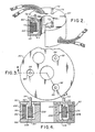
- Figure 2 is a perspective view of a preferred embodiment of the invention with a section removed to depict the principal components and their relative positions within the apparatus.
- the configuration shown is exemplary and not to be construed as limiting.
- the axial bore, the positioning of the supports, etc. plays no part in the efficacy of the present invention and may not be required with other mounting arrangements.
- Other coil dispositions, such as providing a fixed winding on the inner annular wall of a closed core 60, are also useful.
- the closed core 60 comprises a magnetically permeable annular ring 62 having a cavity 64 and a cover plate 66.
- the core 60 is so constructed and arranged that no air gap is permitted at the interface with the cover plate 62.
- a first winding 6$ which may comprise a primary winding for accepting electrical energy is fixedly disposed in the cavity 64 and in stationary contact with the core 62.
- a second electrical winding 70 Positioned within the cavity 64 and radially spaced from the primary winding 68 is a second electrical winding 70 which may comprise a secondary winding for delivering electrical power transferred by inductive coupling to a load, not shown.
- the core 60, the first winding 68, and the second winding 70 comprise a magnetic circuit and that the second winding is positioned for free movement with respect to the core and first winding, while maintaining substantially constant flux coupling independent of the positional relationship with respect to the first winding.
- the closed core 60 which may be comprised of a ceramic based ferrite material, together with the primary coil 68, may be attached to a mounting base and power source, not shown.
- the secondary coil 70 maintains at least a predetermined clearance from the primary coil 68 and the wails of core 62 to minimise the reaction forces noted above, by assuring operation when the secondary 70 is confined with a region of substantially uniform flux linkages, and is attached by supports 72 to the payload or moving element.
- the secondary winding 70 is located within the annular cavity 64 bounded by the walls of magnetically permeable core 62 and the primary coil 68.
- the closed magnetic core 60 surrounds both the primary coil 68 and the secondary coil 70 with no air gap to provide a closed path magnetic circuit coupling the flux from the primary coil to the secondary coil.
- a cylindrical core with an axial through bore is shown, but this is exemplary, and other shapes, such as a solid cylindrical core or a rectangular core, may also be utilised.
- a plurality of apertures 74 is provided for receiving the structural supports 72 with clearance to allow free motion of the secondary coil 70.
- the magnetically permeable core 80 is made up of two or more components to allow the primary coil 82 and the secondary coil 84 to be assembled into the enclosed core.
- the core illustrated is comprised of a cup 86 having an essentially cylindrical body with an annular cavity 88 into which the primary coil 82 and the secondary coil 84 are placed.
- the primary coil 82 is affixed to the outer peripheral wall of the cup 86.
- An end plate 90 is placed in contact with the core 86 to provide an essentially gapless magnetic circuit.
- the core assembly 80 is comprised of a highly magnetic permeable material and must be machined to a close tolerance so that no air gap will be alowed in the magnetic circuit.
- the end plate 90 is provided with apertures 92 through which supports 94, which are fixed to the secondary coil 84, may extend.
- the supports 94 In order to assure no disturbance of the magnetic field, the supports 94 must be formed of a nonmagnetic material.
- the supports 94 in turn, will be coupled to a supporting structure, not shown, on which is mounted a payload for receiving the coupled power.
- the primary coil 82 is comprised of a toroidal winding of magnetic wire 96 wound on an insulating bobbin 98. While the winding 96 of Figure 4 is a single toroidal coil, the winding may also be comprised of several individual coils connected in series and disposed within the cavity 88.
- the secondary coil 84 is a further toroidal winding of magnetic wire 100 on a bobbin 102 which is also formed from an insulating material, such as phenolic plastic.
- Coil 84 is proportioned to provide a mechanical clearance 104 in the vertical direction and a clearance 106 in a horizontal direction to allow the desired freedom of motion in axial, radial, and angular directions.
- the mechanical clearances will be substantially greater than the desired range of motion of the secondary coil 84 to minimise the effects of magnetic disturbance forces on the structure to which the coil 84 is coupled.
- the transformer will provide free movement of 0.05 to 0.50 inches (1.27 mm to 12.7 mm) over six degrees of freedom. It will be clear that while the supports 94 are shown extending through the end plate 90, apertures may alternatively be provided in the base of the core or the sidewalls with appropriate clearances for the primary coil 82.
- the inductive coupler comprised a transformer, wherein the primary coil was wound of seven turns of 525 parallel strands of number 33 AWG insulated copper wire, of the type known as Litz wire to reduce skin effect, and the secondary was wound of two turns of a total of 1750 strands of number 33 AWG Litz wire.
- the core was fabricated of manganese-zinc ferrite material using flat upper and lower plates and inner and outer rings to form the core.
- the coil bobbins were machined from cloth-reinforced phenolic plastic with a wall thickness of 0.075 to 0.125 inches (1.905mm to 3.175mm).
- the transformer leads were terminated at six inches from the transformer body with brass lugs to serve as electrical interfaces to the input and output circuits.
- the coupler described above designed for a 2500 watt power transformer, exhibited a power output substantially independent of the platform displacement with a power transfer efficiency of 99.3%.
- Secondary coil disturbance forces were about 0.0006 ib-ft (0.008135J) axial and less than 0.003 Ib-ft (0.004063J) radial.
- Motion capability was provided of ⁇ 0.20 inches (5.08m) radial, ⁇ 0.75° tilt, and ⁇ 2° rotation.
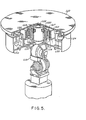
- Figure 5 shows a magnetically suspended movable platform 110 for a precision pointing mount, including an inductive coupler 112 of the present invention of which toroidal core 114 has an annular chamber with a primary winding 116 fixedly mounted therein and energised by a power source, not shown, coupled to a mount 115.
- a movable secondary winding 117 is enclosed within the core 114 and affixed to the platform 110 via non-magnetic supports 118.
- the secondary winding 117 is coupled to energise a payload (not shown), such as optical instruments or an antenna which is mounted on the platform 110, thereby avoiding the use of slip rings or flexible cables.
- Payload data signals are transmitted through the transformer axial bore via an optical coupler (not shown), housed within an axial enclosure 122 in the mount.
- the transformer through-hole allows integration with the optical coupler since it requires operation on the centre line of rotation.
- the enclosed core 114 allows the transformer to be positioned in close proximity to the magnetic bearing assemblies 124 and 126 without imposing undesirable distrubances therebetween due to the flux leakage.
- the platform 110 is magnetically supported and oriented to provide six degrees of freedom by magnetic bearing assemblies 124 and 126 cooperating with armatures 128 and 130, respectively, which support the platform. Since the required range of movement is limited, the clearances between the secondary coil 117 and the core primary windings 116 are made sufficiently large that the force versus displacement characteristics, which are a function of the displacement, provide substantially reduced mechanical forces imposed on the movable platform as a result of energising the primary winding and withdrawing energy from the secondary winding.
- the primary winding 82 is energised by an AC current supply to set up an alternately reversing flux as shown by the flux path 108. Since the flux path 108 is substantially contained within the core 80 and completely surrounds the secondary winding 84, an induced voltage is provided in the secondary winding 84 which is independent of its physical displacement with respect to the primary winding 82. Since all of the core material remains fixed during the motion of the secondary coil 84, there is no magnetic force interaction between permeable magnetic surfaces. Thus, there is provided an essentially forceless restraint of the movement of the secondary winding 84. The secondary coil 84 is free to move throughout the mechanical clearances 104, 106 without significant change in the efficiency of energy transformation.
- the present invention employs a magnetic circuit with no air gaps, which results in limited leakage flux and thus minimises electromagnetic disturbances. Furthermore, since the movable portion of the transformer contains no permeable materials it is substantially independent of disturbances forces.
Landscapes
- Engineering & Computer Science (AREA)
- Power Engineering (AREA)
- Coils Or Transformers For Communication (AREA)
- Coils Of Transformers For General Uses (AREA)
- Control Of High-Frequency Heating Circuits (AREA)
- Emergency Protection Circuit Devices (AREA)
Applications Claiming Priority (2)
| Application Number | Priority Date | Filing Date | Title |
|---|---|---|---|
| US71814985A | 1985-04-01 | 1985-04-01 | |
| US718149 | 1985-04-01 |
Publications (2)
| Publication Number | Publication Date |
|---|---|
| EP0200313A1 true EP0200313A1 (fr) | 1986-11-05 |
| EP0200313B1 EP0200313B1 (fr) | 1990-01-17 |
Family
ID=24885016
Family Applications (1)
| Application Number | Title | Priority Date | Filing Date |
|---|---|---|---|
| EP19860301815 Expired - Lifetime EP0200313B1 (fr) | 1985-04-01 | 1986-03-13 | Transformateur de puissance sans contact et sans force |
Country Status (3)
| Country | Link |
|---|---|
| EP (1) | EP0200313B1 (fr) |
| JP (1) | JPH0652686B2 (fr) |
| DE (1) | DE3668393D1 (fr) |
Cited By (4)
| Publication number | Priority date | Publication date | Assignee | Title |
|---|---|---|---|---|
| EP0374749A1 (fr) * | 1988-12-17 | 1990-06-27 | VOGT electronic Aktiengesellschaft | Transformateur rotatif |
| FR2698220A1 (fr) * | 1992-11-13 | 1994-05-20 | Alcatel Espace | Installation de transmission, sans contact, de puissance électrique. |
| FR2698219A1 (fr) * | 1992-11-13 | 1994-05-20 | Alcatel Espace | Installation de transmission, sans contact, de puissance électrique. |
| GB2280315A (en) * | 1993-07-19 | 1995-01-25 | Secr Defence | Rotatable electric transformer coupling |
Families Citing this family (1)
| Publication number | Priority date | Publication date | Assignee | Title |
|---|---|---|---|---|
| WO2020173865A1 (fr) | 2019-02-25 | 2020-09-03 | Primozone Production Ab | Générateur d'ozone basse fréquence |
Citations (4)
| Publication number | Priority date | Publication date | Assignee | Title |
|---|---|---|---|---|
| US2432982A (en) * | 1942-11-11 | 1947-12-23 | Sperry Gyroscope Co Inc | Inductive coupling |
| US4117436A (en) * | 1976-08-23 | 1978-09-26 | The Charles Stark Draper Laboratory, Inc. | Torqueless relatively moving transformer windings |
| US4303902A (en) * | 1979-08-31 | 1981-12-01 | Westinghouse Electric Corp. | Inductive coupler |
| US4321572A (en) * | 1980-11-13 | 1982-03-23 | The United States Of America As Represented By The Administrator Of The National Aeronautics And Space Administration | Non-contacting power transfer device |
-
1986
- 1986-03-13 DE DE8686301815T patent/DE3668393D1/de not_active Expired - Fee Related
- 1986-03-13 EP EP19860301815 patent/EP0200313B1/fr not_active Expired - Lifetime
- 1986-03-18 JP JP61060448A patent/JPH0652686B2/ja not_active Expired - Lifetime
Patent Citations (4)
| Publication number | Priority date | Publication date | Assignee | Title |
|---|---|---|---|---|
| US2432982A (en) * | 1942-11-11 | 1947-12-23 | Sperry Gyroscope Co Inc | Inductive coupling |
| US4117436A (en) * | 1976-08-23 | 1978-09-26 | The Charles Stark Draper Laboratory, Inc. | Torqueless relatively moving transformer windings |
| US4303902A (en) * | 1979-08-31 | 1981-12-01 | Westinghouse Electric Corp. | Inductive coupler |
| US4321572A (en) * | 1980-11-13 | 1982-03-23 | The United States Of America As Represented By The Administrator Of The National Aeronautics And Space Administration | Non-contacting power transfer device |
Cited By (4)
| Publication number | Priority date | Publication date | Assignee | Title |
|---|---|---|---|---|
| EP0374749A1 (fr) * | 1988-12-17 | 1990-06-27 | VOGT electronic Aktiengesellschaft | Transformateur rotatif |
| FR2698220A1 (fr) * | 1992-11-13 | 1994-05-20 | Alcatel Espace | Installation de transmission, sans contact, de puissance électrique. |
| FR2698219A1 (fr) * | 1992-11-13 | 1994-05-20 | Alcatel Espace | Installation de transmission, sans contact, de puissance électrique. |
| GB2280315A (en) * | 1993-07-19 | 1995-01-25 | Secr Defence | Rotatable electric transformer coupling |
Also Published As
| Publication number | Publication date |
|---|---|
| JPS61231706A (ja) | 1986-10-16 |
| JPH0652686B2 (ja) | 1994-07-06 |
| DE3668393D1 (de) | 1990-02-22 |
| EP0200313B1 (fr) | 1990-01-17 |
Similar Documents
| Publication | Publication Date | Title |
|---|---|---|
| US4754180A (en) | Forceless non-contacting power transformer | |
| US5719451A (en) | Linear magnetic actuator | |
| EP0748024B1 (fr) | Ligne d'alimentation electrique a action directe sans contact | |
| EP0522042B1 (fr) | Dispositif de commande electromagnetique | |
| RU2479880C2 (ru) | Сборка сверхпроводящих катушек и оборудование для генерирования магнитного поля | |
| US20050030140A1 (en) | Multiphase induction device | |
| US4321572A (en) | Non-contacting power transfer device | |
| JPS5956838A (ja) | 密封囲繞体内に配置した回転子の磁気懸架装置 | |
| KR940704077A (ko) | 경량 고출력 기전장치(lightweight high power electromotive device) | |
| JPH0137843B2 (fr) | ||
| US3781580A (en) | Inductor alternator | |
| EP0200313B1 (fr) | Transformateur de puissance sans contact et sans force | |
| EP0024909B1 (fr) | Solénoides | |
| CA2127989A1 (fr) | Actionneur electromagnetique a fil ferromagnetique | |
| US7304559B2 (en) | Rotary transformer for transmission of electrical energy or information | |
| WO1981003575A1 (fr) | Dispositif a solenoide lineaire | |
| US4937546A (en) | Ring-core transformer | |
| GB2361107A (en) | Magnetic bias of a magnetic core portion used to adjust a core's reluctance | |
| KR102651519B1 (ko) | 냉각 기능을 갖춘 계자 유니트 | |
| US20050067910A1 (en) | Bobbinless high-density armature having no substrate, and rotor using the same | |
| KR100360255B1 (ko) | 리니어 모터의 손실 저감구조 | |
| EP0232152A2 (fr) | Vibrateur électromagnétique | |
| JPH05111229A (ja) | 電気エネルギーと機械エネルギーとの変換装置 | |
| CA1159099A (fr) | Dispositif a solenoide lineaire | |
| CN117203439A (zh) | 磁性支承设备 |
Legal Events
| Date | Code | Title | Description |
|---|---|---|---|
| PUAI | Public reference made under article 153(3) epc to a published international application that has entered the european phase |
Free format text: ORIGINAL CODE: 0009012 |
|
| AK | Designated contracting states |
Kind code of ref document: A1 Designated state(s): DE FR GB IT |
|
| PUAB | Information related to the publication of an a document modified or deleted |
Free format text: ORIGINAL CODE: 0009199EPPU |
|
| PUAF | Information related to the publication of a search report (a3 document) modified or deleted |
Free format text: ORIGINAL CODE: 0009199SEPU |
|
| R17D | Deferred search report published (corrected) |
Effective date: 19861210 |
|
| RA1 | Application published (corrected) |
Date of ref document: 19861210 Kind code of ref document: A1 |
|
| 17P | Request for examination filed |
Effective date: 19870206 |
|
| RAP1 | Party data changed (applicant data changed or rights of an application transferred) |
Owner name: HONEYWELL INC. |
|
| 17Q | First examination report despatched |
Effective date: 19880801 |
|
| ITF | It: translation for a ep patent filed |
Owner name: FIAMMENGHI - DOMENIGHETTI |
|
| GRAA | (expected) grant |
Free format text: ORIGINAL CODE: 0009210 |
|
| AK | Designated contracting states |
Kind code of ref document: B1 Designated state(s): DE FR GB IT |
|
| ET | Fr: translation filed | ||
| REF | Corresponds to: |
Ref document number: 3668393 Country of ref document: DE Date of ref document: 19900222 |
|
| PLBE | No opposition filed within time limit |
Free format text: ORIGINAL CODE: 0009261 |
|
| STAA | Information on the status of an ep patent application or granted ep patent |
Free format text: STATUS: NO OPPOSITION FILED WITHIN TIME LIMIT |
|
| 26N | No opposition filed | ||
| ITTA | It: last paid annual fee | ||
| PGFP | Annual fee paid to national office [announced via postgrant information from national office to epo] |
Ref country code: FR Payment date: 19931214 Year of fee payment: 9 |
|
| PGFP | Annual fee paid to national office [announced via postgrant information from national office to epo] |
Ref country code: GB Payment date: 19931220 Year of fee payment: 9 Ref country code: DE Payment date: 19931220 Year of fee payment: 9 |
|
| PG25 | Lapsed in a contracting state [announced via postgrant information from national office to epo] |
Ref country code: GB Effective date: 19950313 |
|
| GBPC | Gb: european patent ceased through non-payment of renewal fee |
Effective date: 19950313 |
|
| PG25 | Lapsed in a contracting state [announced via postgrant information from national office to epo] |
Ref country code: FR Free format text: LAPSE BECAUSE OF NON-PAYMENT OF DUE FEES Effective date: 19951130 |
|
| PG25 | Lapsed in a contracting state [announced via postgrant information from national office to epo] |
Ref country code: DE Effective date: 19951201 |
|
| REG | Reference to a national code |
Ref country code: FR Ref legal event code: ST |
|
| PG25 | Lapsed in a contracting state [announced via postgrant information from national office to epo] |
Ref country code: IT Free format text: LAPSE BECAUSE OF NON-PAYMENT OF DUE FEES;WARNING: LAPSES OF ITALIAN PATENTS WITH EFFECTIVE DATE BEFORE 2007 MAY HAVE OCCURRED AT ANY TIME BEFORE 2007. THE CORRECT EFFECTIVE DATE MAY BE DIFFERENT FROM THE ONE RECORDED. Effective date: 20050313 |