EP0200275B1 - Multiplex information transmission system - Google Patents
Multiplex information transmission system Download PDFInfo
- Publication number
- EP0200275B1 EP0200275B1 EP86200727A EP86200727A EP0200275B1 EP 0200275 B1 EP0200275 B1 EP 0200275B1 EP 86200727 A EP86200727 A EP 86200727A EP 86200727 A EP86200727 A EP 86200727A EP 0200275 B1 EP0200275 B1 EP 0200275B1
- Authority
- EP
- European Patent Office
- Prior art keywords
- channels
- channel
- multiplex
- information
- transmission
- Prior art date
- Legal status (The legal status is an assumption and is not a legal conclusion. Google has not performed a legal analysis and makes no representation as to the accuracy of the status listed.)
- Expired - Lifetime
Links
Images


Classifications
-
- H—ELECTRICITY
- H04—ELECTRIC COMMUNICATION TECHNIQUE
- H04J—MULTIPLEX COMMUNICATION
- H04J3/00—Time-division multiplex systems
- H04J3/16—Time-division multiplex systems in which the time allocation to individual channels within a transmission cycle is variable, e.g. to accommodate varying complexity of signals, to vary number of channels transmitted
- H04J3/1682—Allocation of channels according to the instantaneous demands of the users, e.g. concentrated multiplexers, statistical multiplexers
-
- H—ELECTRICITY
- H04—ELECTRIC COMMUNICATION TECHNIQUE
- H04W—WIRELESS COMMUNICATION NETWORKS
- H04W52/00—Power management, e.g. TPC [Transmission Power Control], power saving or power classes
- H04W52/02—Power saving arrangements
- H04W52/0209—Power saving arrangements in terminal devices
- H04W52/0225—Power saving arrangements in terminal devices using monitoring of external events, e.g. the presence of a signal
- H04W52/0229—Power saving arrangements in terminal devices using monitoring of external events, e.g. the presence of a signal where the received signal is a wanted signal
- H04W52/0232—Power saving arrangements in terminal devices using monitoring of external events, e.g. the presence of a signal where the received signal is a wanted signal according to average transmission signal activity
-
- Y—GENERAL TAGGING OF NEW TECHNOLOGICAL DEVELOPMENTS; GENERAL TAGGING OF CROSS-SECTIONAL TECHNOLOGIES SPANNING OVER SEVERAL SECTIONS OF THE IPC; TECHNICAL SUBJECTS COVERED BY FORMER USPC CROSS-REFERENCE ART COLLECTIONS [XRACs] AND DIGESTS
- Y02—TECHNOLOGIES OR APPLICATIONS FOR MITIGATION OR ADAPTATION AGAINST CLIMATE CHANGE
- Y02D—CLIMATE CHANGE MITIGATION TECHNOLOGIES IN INFORMATION AND COMMUNICATION TECHNOLOGIES [ICT], I.E. INFORMATION AND COMMUNICATION TECHNOLOGIES AIMING AT THE REDUCTION OF THEIR OWN ENERGY USE
- Y02D30/00—Reducing energy consumption in communication networks
- Y02D30/70—Reducing energy consumption in communication networks in wireless communication networks
Definitions
- the present invention relates to a system for transmitting information between at least two stations for transmitting free or occupied channel information, each station having at least one transmitter circuit and one radio receiver circuit supplied by means of a source of power supply and means to detect free or occupied channels.
- station equipment such as the transmitter and receiver circuits are always supplied with power and consume energy even when there is little or no information to transmit, for example, during very busy hours. low traffic densities, especially at night.
- the invention aims to remedy this drawback and provides means for very significantly reducing energy consumption.
- the information transmission system of the kind mentioned in the preamble is remarkable in that it has means cooperating with the detection means to implement a method for developing a time multiplex formed of an elementary frame of duration.
- T in which the information originating from the occupied channels is grouped side by side in said elementary frame and means for reducing the consumption of the transmitter circuit and of the receiver circuit from the detection of free channels and for supplying normally the transmitter circuit and the receiver circuit from the detection of busy channels.
- the idea of the invention is based on the fact that in order to significantly save the energy of the different stations, the transmitter circuits and the receiver circuits should only operate when there is useful information to be transmitted.
- the multiplex frame is organized in such a way that the channels used permanently, that is to say the so-called service channels (rhythm, synchronization, signals, ...) and the channels assigned to the so-called busy demand are grouped for example at the start of the multiplex frame, which has the effect, in the event of light traffic, of presenting a large number of contiguous channels unused at the end of the frame.
- the signaling channels information is transmitted which makes it possible to know which channels are used and the number of the last channel used in the frame.
- the transmitter and receiver circuits can therefore be cut from the last channel used, however they must be reactivated before the start of the new frame in order to take account of their response time.
- the response time of the transmitter and receiver circuits is less than the duration T of a multiplex frame, it is nevertheless of the same order of magnitude and the energy saving thus obtained is relatively low. For this and to significantly increase the energy saving, it reduces the influence of the response time of the transmitter and receiver circuits.
- the invention proposes means for reducing the influence of the response time of the transmitter and receiver circuits.
- the information transmission system in which the elementary multiplex frames transport information relating to service channels and information relating to data channels, is remarkable in that it comprises further means for grouping the elementary multiplex frames n by n, the service channels and the occupied data channels being grouped n by n and side by side in the new frame obtained.
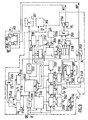
- FIGS. 7 and 8 propose a block diagram of a device for transforming the multiplex and for controlling the transmitter circuit.
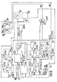
- Figures 9 and 10 provide a block diagram of a multiplex retransformation device and receiver circuit control.
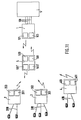
- Figure 11 shows a variant of the transmission system according to the invention using more than two stations.
- Figure 1 is shown schematically an information transmission system in which the invention is used.
- the essential functions of such a system are to concentrate the telephone traffic and to transmit this traffic, in a completely transparent manner, over the air between a central station 1 attached to a telephone exchange (not shown in the figure) and at least one remote station 2 associated with a subscriber group.
- the central station 1 is under the control of a control and storage device 100 managing and storing information to be transmitted by radio to the remote station 2 by means of the transmitter circuit 101 and its antenna 102 and information received by the receiver circuit 103 and its antenna 104 from the remote station 2.
- the transmitter circuits 101 and receiver 103 are supplied by means of a power source U.
- the transmitter circuit 101 has organs 101 L which, when the control is switched on, have significant response times (of the order of 100 ⁇ s, such as a local oscillator, a synthesizer, etc.) and organs. 101 C which have shorter response times (around 20 for a modulator, and much less for an amplifier).
- the receiver circuit 103 has organs 103L having long response times during start-up (such as a local oscillator, a synthesizer, etc.) and organs 103C, the response times of which are shorter (such as than a demodulator, an amplifier ).
- An interface device 105 synchronous with the control and storage device 100, CBTE signal, provides the link between the control and storage device 100 and the telephone exchange with regard to the signals relating to the different communication channels, signals to send IE, signals received IR.
- the interface device 105 also connects the telephone exchange with a transmission time connection network 106 with regard to the data to be transmitted DE and with a reception time connection network 107 with regard to the data received DR .
- the interface device 105 is connected to the telephone exchange by means of telephone pairs 108.
- the control and storage device 100 controls the operations of the transmission time connection network 106 by means of addressing control signals SCAE and of CBTE synchronization and the reception time connection network 107 by means of SCAR addressing control signals and CBTS synchronization.
- the control and storage device 100 comprises the means for detecting the free or occupied channels, means which will be described with the aid of FIG. 4.
- a 32-channel multiplex shown in FIG. 2 is chosen, at the output of the transmission time connection network 106 is then a single 32-channel SDE link, multiplexed by a multiplexer 109 which receives other share the command and signaling signals of the OS channels and a control signal C from the control and storage device 100. These signals thus multiplexed are transmitted to the transmitter circuit 101.
- the receiver 103 transmits the signals received to the reception time connection network 107 (EDR signals) and to reception time connection 107 (EDR signals) and to the control and storage device (SS signals).
- the structure of a remote station 2 is symmetrical to that of the central station 1.
- the remote station 2 is also under the control of a control and storage device 200 synchronous with that of the central station and has a transmitter circuit 201 and an antenna 202 and a receiver circuit 203 and an antenna 204.
- the transmitter 201 and receiver 203 circuits have the same characteristics as the transmitter 101 and receiver 103 circuits of central station 1 and are also supplied by means of a voltage source. U (not shown in the figure).
- An interface device 205 provides the link between the control and storage device 200 and the subscriber equipment with regard to the signals relating to the different communication channels, signals to be sent IE ', signals received IR'.
- the interface device also connects the subscriber equipment with a transmission time connection network 206 with regard to the data to be transmitted DE 'and with a reception time connection network 207 with regard to the data received DR '.
- the interface device 205 is connected to the subscriber equipment by means of telephone pairs 208.
- the control and storage device 200 controls the operations of the transmission time connection network 206 by means of addressing control signals SCAE 'and the reception time connection network 207 by means of SCAR addressing control signals'.
- the output SDE 'of the transmission time connection network 206 is connected to a multiplexer 209 which also receives command and signaling signals of channels SS' and a control signal CBDT coming from the control and storage device 200. These signals, once multiplexed, are transmitted to the transmitter circuit 201.
- the receiver 203 transmits the signals received to the reception time connection network 207 (signals EDR ') and to the control and storage device 200 (signals OS').
- the information transmission system between at least two stations for transmitting information from free and occupied channels, each station having at least one transmitter circuit and one radio receiver circuit supplied by means of a power source and means for detecting the free or occupied channels is remarkable in that it has means cooperating with the detection means to implement a method for developing a time multiplex formed of an elementary frame of duration T , in which the information coming from the occupied channels is grouped side by side in said elementary frame and means for reducing the consumption of the transmitter circuit and of the receiver circuit from the detection of free channels and for supplying the transmitter circuit and the power supply normally receiver circuit from detection of occupied channels.
- control and storage device 100 cooperates with means 100 ′ to implement a method for grouping the channels occupied side by side in the multiplex frame, this method will be described with the aid of FIG. 6.
- the information transmission system in which the elementary multiplex frames transport information relating to service channels and information relating to data channels is remarkable in that it comprises in addition to means for grouping the elementary multiplex frames n by n, the service channels and the occupied data channels being grouped n by n and side by side in the new frame obtained.
- a device for transforming the multiplex and for controlling the transmitter circuit 110 between the multiplexer 109 and the transmitter circuit 101 is advantageously inserted a device for transforming the multiplex and for controlling the transmitter circuit 110, likewise between the receiver circuit 103 and the reception time connection network 107 on the one hand and the control and storage device 100 on the other hand is also inserted a device for retransformation of the multiplex and control of the receiver circuit 111.
- the output of the multiplexer 109 is connected to the input of the device 110 which receives on the other hand, a clock H produced by the control and storage device 100.
- the information transmission system in which each station, central or remote is equipped with at least one transmitter circuit and one receiver circuit is remarkable in that it further comprises means for cut and supply either partially or completely the transmitter and receiver circuits.
- An additional energy saving is thus obtained.
- the restarting and therefore the supply of a transmitter circuit or a receiver circuit is partially ensured three ways before the end of the frame for the components 101 L and 103L which take the longest to operate while the components 101C and 103C faster to return to function are supplied one channel or less before the end of the frame, the total supply of the transmitter or receiver circuits then being ensured. In this way the transmitter circuit or the receiver circuit is again ready to transmit the information from the start of the new frame.
- the device 110 From the input signals (multiplex, clock H) the device 110 on the one hand transmits a partial start signal MP and a total start signal MT, intended to supply partially or completely the transmitter circuit 101 , and on the other hand it transforms the elementary multiplex of duration T into an elongated multiplex of duration nT.
- the signal MP is applied to a switch 101 A which, when the signal MP is active connects the power supply U to the organs 101 L of the transmitter circuit 101.
- the signal MT is applied to a switch 101 B which when the signal MT is active connects the supply U to the organs 101 C.
- the MP and MT signals are active, the extended multiplex present at the input of the transmitter circuit is then transmitted by radio to the remote station 2.
- the multiplex retransformation and receiver circuit control device 111 which also receives the clock H, prepares the partial start signal MP'C applied to the switch 103A intended to supply by means of the supply U the organs 103L, the total start signal MT'C applied to the switch 103B intended to supply by means of the power supply U the organs 103C and transforms the elongated multiplex of duration nT into an elementary multiplex of duration T.
- a device for transforming the multiplex and for controlling the transmitter circuit 210 identical to the device 110 of the central station 1.
- a device for retransformation of the multiplex and receiver control 211 is also inserted.
- the output of the multiplexer 209 is connected to the input of the device 210 which also receives a clock H 'sent by the control and storage device 200.
- the device 210 emits a partial start signal MPD and a full start signal MTD to supply either partially or completely the transmitter circuit 201 and transforms the elementary multiplex into an elongated multiplex.
- the MPD and MTD signals are active, the extended multiplex is then transmitted by radio to central station 1 (the MPD and MTD signals being produced identically to the MP and MT signals).
- the device for retransforming the multiplex and for controlling the receiving circuit 211 which also receives the clock H 'generates the partial start signal MP', the total start signal MT 'and transforms the elongated multiplex back into a elementary multiplex.
- the signals MP 'and MT' being developed in total identity with the signals MP'C and MT'C.
- FIG. 2 represents a multiplex comprising occupied channels and free channels.
- a frame TR consists of 32 channels V0, V1, V2, V3, V4, V5, V6, ..., V29, V30, V31.
- Some channels are busy and are referenced 0 such as V0, V1, V2, V4, ..., other channels are free, they are referenced L, such as V3, V6, ...
- L such as V3, V6, ...
- the elementary frame therefore before grouping of n frames, comprises three service channels and thus has 29 data channels for a 32-channel frame.
- the service channels carry the rhythm, the frame and multiframe locking words and the signaling channel.
- Data channels carry data relating to communications. When a data channel is not busy, it carries rhythm.
- the information transmission system according to the invention the service channels of which carry the timing signal, the frame and multiframe alignment words and the signaling link is remarkable in that the timing signal is transmitted at the very start of a multiplex frame.
- the transmission system is also characterized in that the channel status information (free or occupied) and the number of the last channel used are transmitted in the multiplex.
- the frame contains in the example 32 numbered channels from VO to V31, each channel has a byte therefore of 8 bits.
- the multiframe comprises 32 frames numbered from 0 to 31.
- the frame locking word is present every other time in frames of even rank, for example.
- the number of the last channel used is present every other time in frames of odd rank.
- Bits a0, b0, c0, d0 represent the signaling of the channel having the same number as the frame and bits a1, b1, c1, d1, represent the signaling of the channel having the same number as the frame increased by unit.
- bits a, b, and c represent the signaling of the trunk or the equipment to which the channel has been assigned, the bit d representing the busy state of the channel.
- Channels 3 to 31 are assigned to subscribers.
- the configuration of the multiplex is therefore as follows:
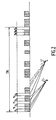
- FIG. 3 represents the transformation of an elementary frame into an elongated frame.
- the number of frames grouped according to the invention was chosen equal to 8.
- the referenced channels of each elementary frame are 32 in number: V0, V1, V2, V3, V4, ..., V30, V31.
- the channels of the extended multiplex are referenced M, thus the channel MO contains 8 elementary channels V0, the channel M 1 contains 8 elementary channels V1, ... and the channel M31 contains 8 elementary channels V31.
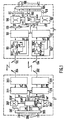
- FIG 4 is proposed a block diagram of the central station 1.
- the control and storage device 100 is controlled by a control unit 1100 developed around a microprocessor.
- the control unit 1100 is provided with a BUSA address line and a BUSD data line and is thus associated with random access memories 1101, read-only memories 1102 and an interface box 1103 ensuring the management of the signaling channel facilitating the dialogue between station: central and remote station.
- the interface device 105 consists of junctions 1104e, 1104b, ..., providing the connection between the central station 1 and the switchboard of the telephone exchange (not shown), by means of telephone pairs 108. There are as many trunks only of subscriber lines to be connected.
- the control and storage device 100 has a transmission time base 1105 which supplies CBTE control signals to the various trunks 1104a, 1104b, .... in order to carry out the coding and decoding of the LF signals of speech, to recover the transmitted signals (state of the loops) and to issue the orders (ringing, teletax, battery reversal) which are detected on the connection lines to the telephone exchange.
- the control signal CBTE also controls the transmission time connection network 106.
- the device 100 also has a reception time base 1106.
- the concentration of the speech channels on the channels of the multiplex link is carried out after detection of the off-hook information from a subscriber of a remote station transmitted by the signaling link or information concerning a new call generated by the PABX (not shown).
- the detection of the new call is made by the device 100 through an order memory 1107 preceded by a multiplexer 1108, in which are systematically written all the orders from the subscriber junctions, signal lE.
- the control unit 1100 periodically reads this command memory 1107 through a multiplexer 1109 and thus detects changes in state.
- the assignment of a channel to a trunk is performed by means of the time connection network 106 and a control memory 1110 preceded by the multiplexer 1111.
- the control memory 1110 of the connection network 106 and the multiplexer 1111 are located in the device 100.
- the connection network 106 is essentially constituted by memories in which the coded LF channels coming from the trunks, DE signals are systematically written.
- SDE signal At the output of the connection network 106 there is only one 32-channel link, SDE signal, if the multiplex is chosen to 32 channels.
- the concentration is carried out by reading the reserved time (CBTE signal emitted by the time base 1105) at the output channel the content of the word corresponding to the input channel that we want to switch there.
- the read addresses are delivered by the control memory 1110, SCAE signals.
- control unit 1100 To assign a channel, the control unit 1100 therefore writes in memory 1110 to the address corresponding to the output channel, the number of the input channel that it wants to connect to it.
- the SCAE read addresses delivered by the memory 1110 also serve to come to read in the command memory 1 107 the signals to the channels which have been concentrated (signaling channel by channel).
- control unit 1100 writes into a channel occupation memory 1112 of 32 x 1 bits, the channel occupation state, a multiplexer 1113 is associated with the memory 1112.
- the reading of this memory is done at the same time as that of the 1107 command memory: in this way the signaling channel by channel SVV transmits the state of the channel, occupied or free, at the same time as the signaling of the trunk which is connected to it.
- the reading and writing in the command memories 1107, of command 1110 and of occupation of the channels 1112 are done in synchronism with the transmission time base 1105, signal CBTS.
- the multiplexer 109 is controlled by the control signal C transmitted by the transmission time base 1105.
- the signal at the output of the multiplexer 109 is transmitted to the transmitter circuit 101.
- the receiving circuit 103 transmits the information received to the reception time connection network 107, signal EDR, and to the device 100, signals SS.
- the SS signals comprise on the one hand the signals from the channels which are transmitted to a signaling memory 1115 located in the device 100 and on the other hand the information of the signaling channel which are transmitted to the interface unit 1103.
- the information received also makes it possible to reconstruct the reception time base 1106 from the frame alignment words contained in said information. This time base 1106 makes it possible to extract the different channels of the frame and of the multiframe.
- the signaling memory 1115 is preceded by the multiplexers 1116 and 1117, while a control memory 1118, preceded by a multiplexer 1119 addresses the reception time connection network 107 by means of the control signals. SCAR addressing.
- the reception time connection network 107 and the signaling memory 1115 operate identical to that of the transmission time connection network 106 and the command memory 1107 on transmission.
- At the input of the connection network 107 is a single multiplex link, EDR signal, while at its output are transmitted the information received on a plurality of multiplex links, DR signals.
- the control unit 1100 writes in the control memory 1118 to the address corresponding to an input channel of the connection network 107 the number of the output channel that it wants to connect to it, at the instant defined by the CBTR control signal emitted by the reception time base 1106.
- the channel-by-channel signals contained in the frame are systematically written in the signal memory 1115 to the SCAR addresses delivered by the control memory 1118.
- Reading from the memory 1118 command and therefore the systematic writing in the connection network 107 and in the signaling memory 1115 are done in synchronism with the reception time base 1106, signal CBTR, while the systematic reading of the signaling memory 1115 and the connection network 107 are synchronized with the transmission time base 1105, CBTS signal.
- the control unit 1100 writes the idle code at the addresses corresponding to the trunks which are not connected to the input channels.
- the connection is identical in the transmit and receive directions, the same channel is assigned to the same trunk, IR signal.
- the control and storage device 100 cooperates with means 100 ′ to implement a method for grouping the occupied channels side by side in the multiplex frame.
- the means 100 ′ are read only memories in which the various states relating to the process are written (described with the aid of FIG. 6) which is used to group the occupied channels side by side. .
- the microprocessor of the control unit 1100 is in relation to the means 100 'via the address line BUSA and the data line BUSD.
- the device for transforming the multiplex and for controlling the transmitter circuit 110 between the multiplexer 109 and the transmitter circuit 101 is inserted the device for transforming the multiplex and for controlling the transmitter circuit 110, likewise between the receiver circuit 103 and the network of reception time connection 107 on the one hand and the command and storage device 100 on the other hand is inserted the device for retransformation of the multiplex and command of the receiver circuit 111.
- a clock H, transmitted by the time base d transmission 1105 is used by the devices 110 and 111.
- the device 110 transmits the signals MT and MP to the transmitter circuit 101, while the device 111 transmits the signals MT'C and MP'C to the receiver circuit 103.
- the devices 110 and 111 will be described respectively using FIGS. 7, 8 and 9, 10.
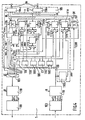
- FIG. 5 a block diagram of the remote station 2 is proposed, the structure of which is symmetrical to that of the central station 1.
- the control and storage device 200 is controlled by a control unit 2100 constructed around a microprocessor .
- the control unit 2100 is provided with an address line BUSA 'and a data line BUSD' and is thus associated with random access memories 2101, read-only memories 2102 and with an interface box 2103 ensuring the signaling link management.
- the interface device 205 provides the link between the remote station and the subscriber equipment by means of telephone pairs 208, it is made up of junction circuits 2104a, 2104b, ... There are as many trunk circuits as there are subscriber lines.
- the control and storage device 2100 has a unique time base 2105, reconstructed from the received multiplex, which supplies CBDT control signals to the various trunk circuits 2104a, 2104b, etc.
- the remote station is likewise provided with reception of an order memory 2106, preceded by the multiplexers 2107 and 2108.
- the memory 2106 at the addresses provided by the control unit 2100, all the orders (output signal IR ′) concerning the circuits are systematically written subscriber junction, from the received multiplex frame (OS 'signals) and the data supplied by the control unit 2100, in synchronism with the CBDT signal transmitted by the time base 2105.
- the channel occupancy signaling is also fed back to the transmission via the multiplexer 209.
- the assignment of a channel to a junction circuit is carried out by means of a reception time connection network 207 and a control memory 2109 pr transferred from the multiplexer 2110.
- the memory 2109 and the multiplexer 2110 are located in the device 200.
- At the input of the reception time connection network 207 is transmitted the received multiplex EDR ', while at its output a plurality of multiplex links DR 'are transmitted to the various junction circuits.
- the write addresses SCAR ′ are supplied by the control memory 2109.
- To assign a channel the control unit 2100 writes in the memory 2109 to the address corresponding to the output channel the number of the input channel that 'it wants to connect to it, in synchronism with the CBDT signal emitted by the time base 2105.
- the write addresses SCAR' delivered by the me moire 2109 are also used to write in the command memory 2106 the signals of the channels.
- the device for transforming the multiplex and for controlling the transmitter circuit 210 between the multiplexer 209 and the transmitter circuit 201 is inserted the device for transforming the multiplex and for controlling the transmitter circuit 210, likewise between the receiver circuit 203 and the network of reception time connection 207 on the one hand and the control and storage device 200 on the other hand is inserted the device for retransformation of the multiplex and control of the receiver circuit 211.
- a clock H 'transmitted by the reconstituted time base 2105 is used by the devices 210 and 211.
- the device 210 and the device 211 are respectively identical to the devices 110 and 111 of the central station 1.
- the device 210 transmits the signals MTD and MPD to the transmitter circuit 201, while the device 211 transmits the signals MT 'and MP' to the receiving circuit 203.
- the description of the remote station 2 completed it should be noted that beyond the symmetry existed nt between central station and remote station, there are some differences. In fact, the remote station is synchronous with the central station, so the time base 2105 recovered at the reception is unique and therefore also used for transmission.
- the control of the time connection networks 206 and 207 is also ordered by the central station.
- the number of the last channel used written in circuit 2116 which is retransmitted in the transmitted frame is extracted from the received frame.
- the state of occupation of the channels, retransmitted in the signaling channel by channel is the same as that received in the incident frame, it is therefore a copy of the channel signaling recorded in the order memory 2106 ..
- FIG. 6 is proposed an application diagram of a method implemented to group according to the invention, in a given configuration, the channels occupied in the multiplex.
- the allocation of the channels on the multiplex is carried out by the central station upon detection of an incoming call from the telephone exchange, or when a subscriber connected to a remote station picks up.
- the channels VO to Vi of the multiplex are service channels (rhythm, frame and multiframe synchronizations, signals) and are always present in the frames.
- the channels Vi + 1 to Vn of the multiplex are data channels which evolve between the "free" and "occupied” states. A data channel is said to be occupied when a communication has been associated with this channel. All data channels are in the "free" state when the network is commissioned.
- the service channels are always assigned at the start of the frame and to optimize the use of the frame, the central station assigns, when establishing communications, the lowest ranking data channels from Vi + 1 to 'to Vn.
- Two cases can occur relative to the taking into account of calls, the call comes either from the telephone exchange, or from a subscriber connected to a remote station (at the moment when the subscriber picks up his telephone track).
- the method used for assigning a channel is the same and the diagram in FIG. 6 provides a solution to all of these two cases.
- the method which will be described is implemented in the device 100 via the means for detecting free or occupied channels and means 100 ′ containing the different states of said method.
- the call is made by the telephone exchange.
- the initial state P0 the associated trunk is at rest.
- the incoming call from the telephone exchange this is the state P1
- r, i and n represent the rank of a channel in the frame
- i + 1 represents the first possible assignment rank for a data channel
- n represented the last possible assignment rank
- r is the rank which is imposed at the time of the assignment.
- state P6 If it is occupied, the procedure returns to states P4, P5 as long as no free route is found or as long as the assignment is not refused (state P6).
- state P7 When the prospected rank channel is free, state P7 is established, the prospected rank channel is declared occupied (transmission of a channel occupation bit) and the assignment accepted, the trunk is in communication. At the end of the communication, the channel used is released, this is the P8 state, the channel is declared free (transmission of the channel occupation bit).
- the last state, state P9 is equivalent to state P0, that is to say that the circuit breaker is again at rest.
- the process is absolutely identical.
- the initial state PO the subscriber equipment is at rest and the state P1 is caused by the subscriber picking up the telephone set.
- the states P2, P3, P4, P5, P6, P7 and P8 are the states described in the first case.
- the state P9 is also equivalent to the initial state P0, that is to say that the subscriber equipment is again at rest.
- a reorganization of the frame is decided by the central station in order to group the communications on the low-ranking data channels.
- the organization of the frame is analyzed on expiry of a time delay of duration D.
- the reorganization is only decided when the condition below is true: being chosen by the operator)
- This condition expresses the relationship between the number of communications likely to be established during the coming period D and the number of communication channels in the free state between Vi and Vh. As long as this ratio remains greater than or equal to 1, it is not opportune to impose a reorganization of the multiplex, on the other hand as soon as this ratio becomes very less than 1, a reorganization is necessary.
- the software of the central station transfers the communications associated with the highest-ranking channels to the free low-ranking channels, starting with the communication associated with the occupied highest-ranking channel Vh.
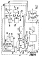
- FIG. 7 is proposed the block diagram of the device for transforming the multiplex and for controlling the transmitter circuit 110 identical to the device 210.
- the transmission system is remarkable in that it has means to reduce the consumption of the transmitter circuit and the receiver circuit from the detection of free channels and to supply the transmitter circuit and the receiver circuit normally from the detection of busy lanes.
- the means for detecting the free or occupied channels have been detailed, they are constituted by the control unit 1100 and the command memories 1107 and of occupation of channels 1112.
- the response time when switching on the transmitter and receiver circuits is not negligible relative to the duration of a multiplex frame commonly used in this type of application (for example: multiplex 32 tracks at 125 Jls recurrence). Also to reduce the influence of the response time of the transmitter and receiver circuits and therefore advantageously increase the energy saving, the organization of the multiplex frame is carried out differently.
- the transmission system comprises means for grouping the elementary multiplex frames n by n, the service channels and the occupied data channels being grouped n by n and side by side in the new frame thus obtained.
- the elementary multiplex frame (with 32 channels for example) is transformed into a frame n times longer and the n channels of the same rank are grouped side by side.
- There is a series of counters composed of a bit counter 1168, a channel counter 1170, a frame counter 1171, a memory selection flip-flop 1172 making it possible to address a part of a memory. These four counters are synchronous with the clock H emitted by the time base 1105 (FIG. 4) and in phase relative to the frame, (they could be part of the time base 1105).
- the multiplexer 109 controlled by the signal C coming from the time base 1105 (FIG. 4) allows to insert in the elementary frame (before regrouping of the frames n by n) various signals such as the rhythm signal R, the frame locking words VT and of multiframe VMT, the number of the last channel used NDV, the signals of of the SVV channels, the signaling channel CS and the signals relating to the SDE data channels.
- the output of the multiplexer 109 is connected to the input of a serial-parallel converter 1174, the output of which is connected to a memory circuit 1175.
- the transformation of the elementary multiplex into an elongated multiplex comprising n frames is carried out by means of the memory 1175 can contain twice n frames.
- the memory 1175 is under the control of the various address signals from the counters 1170, 1171 and the flip-flop 1172 which makes it possible to choose the half of memory concerned, all of its signals are multiplexed by the multiplexer 1176.
- the time d access to memory 1175 at the rate of the channels V is divided into two: a time for writing and a time for reading.
- the control of the multiplexer 1176 is obtained from a decoding circuit 1169 controlled from the signals of the bit counter 1168.
- the flip-flop 1172 "choice of memory" delivers the address wire A8 indicating the part of the memory concerned.
- the writing in the memory is done in the half indicated by the state of A8, at the addresses fixed by the commands: A0, A1, A2, A3, A4, A5, A6, A7.
- the memory is read in the half indicated by the state of at the addresses set by the commands A3, A4, A5, A6, A7, A0, A1, A2.
- the output of memory 1175 is then connected to a serial parallel converter 1177, the output of which is connected to the transmitter circuit 101.
- the transmission of the channel state information (free or occupied) and the number of the last channel used are used to develop the signals to cut and supply either partially or completely the transmitter and receiver circuits. .
- the information transmission system is remarkable in that when the transmission of the channel state information is used to cut and supply either partially the transmitter and receiver circuits, the transmission of a channel data after several free channels is immediately preceded by the emission of a rhythm channel.
- each channel lasts the time of n elementary channels and the channel validation information is used to deactivate and activate the organs 101 1 (MP signal) and the organs 101 C (MT signal) of the transmitter circuit 101, instead base the deactivation and commissioning only on the row of the last track used.
- the channel validation information is used to deactivate and activate the organs 101 1 (MP signal) and the organs 101 C (MT signal) of the transmitter circuit 101, instead base the deactivation and commissioning only on the row of the last track used.
- the partial start command for the transmitter circuit is developed from a counter 1178 and a comparator 1179 which permanently compares the state of this counter with the number of the last channel used NDV.
- the NDV signal is taken at the input of the multiplexer 109, it is thus always present at the input of the comparator 1179.
- the frequency of transmission of the information relating to the channels coming from the channel counter 1170 is the clock which is applied to an input of an AND circuit 1180, to the other input of circuit 1180 is applied the inverted output signal of comparator 1179, the output signal of circuit 1180 thus makes it possible to advance the counter at the rate of the clock. As soon as there is equality between the number of the last channel used and the state of the counter 1178, it is stopped.
- the signal of the frame counter 1171 decoded by the decoder 1181 allows the reset of the counter 1178 (signal RZ) after detection of the last channel of the frame.
- the output of comparator 1179 is applied to the input of a flip-flop 1182 whose second input receives the clock transmitted at the frequency of transmission of information relating to the channels.
- the output of flip-flop 1182 thus controls the partial start-up of the transmitter circuit.
- the output of flip-flop 1182 is connected to an input of an OR circuit 1183, a time slot is imposed on the second input of the OR circuit 1183, this slot is obtained by decoding the signals (decoder 1181) from the time base and has duration for the last three channels of the frame.
- the signal at the output of circuit 1183 thus ensures three-way partial start-up before the start of the frame (MP signal).
- MPE signal can be that of the control unit 100, (in this case, it is enough to connect and use the data line BUSD), it is read under the command of the CA addresses (keeping the example proposed above: A3, A4, A5, A6, A7).
- the access time to the memory is divided into two: a time reserved for writing and a time reserved for reading. The writing is done by the microprocessor only when it has to change the con held in memory (assigning a channel or deleting a channel).
- the microprocessor delivers on its MPA address bus (or BUSA which it suffices to connect if the control unit 100 is used), the address where it wants to write and on its MPE data bus the new information. to write.
- MPA address bus or BUSA which it suffices to connect if the control unit 100 is used
- MPE data bus the new information. to write.
- This separation between the write and read times is carried out by means of a multiplexer 1186 at the input of which the read and write addresses are located.
- the control of this multiplexer comes from a decoding circuit 1173 whose inputs come from the counters 1168, 1170 and 1171.
- the memory is read systematically under the control of the CA addresses present at the output of the counters 1170 and 1171 with two ways ahead.
- the CA addresses, controlling the reading of the memory 1184, which are presented at the input of the adder circuit 1185 are delivered by the adder circuit 1185 with two times of advance, the circuit 1185 systematically shifting the CA addresses by 2 not.
- the output of circuit 1185 is connected to an input of multiplexer 1186, a second input of which receives the address signal from the microprocessor (MPA signal, or address line BUSA), the output of the multiplexer being connected to memory 1184.
- the output memory is connected to the input of a shift register 1187 the result of the reading is memorized three times in order to control the start-up two channels before the channel actually occupied, and thus allow to transmit a channel of rhythm before the path actually occupied.
- An OR circuit 1188 has three of its inputs connected to the three outputs of register 1187 representing the reading of the memory plus the two previous readings.
- a fourth input of this OR circuit 1188 receives a time slot command from the decoding circuit 1181. The duration of this slot corresponds to the last channel of the frame (therefore to the channel preceding the new frame) and to the three channels of service M0, M 1 and M2.
- the output of the OR circuit 1188 is connected to the input of an AND circuit 1189 which controls the total start-up (signal MT) of the transmitter circuit 101 when its second input sees the partial start-up signal (MP) active, thus validating the total start-up.
- the delay time of 20 times with respect to the control of the organs 101 C is taken as an example. If this command acts only on output amplifiers, the response time is negligible. Under these conditions, the MT total start command must arrive at the time when it is actually wanted to transmit. In the diagram of FIG. 7, it suffices to read the memory 1184 with a time in advance.
- the circuit 1185 then shifts the addresses CA by one step and the shift register 1187 comprises only two stages: the result of the reading of the memory 1184 is stored twice.
- the two outputs of register 1187 are connected to two inputs of the OR circuit 1188.
- the time slot from the circuit 1181 and connected to the third input of the OR circuit 1188 corresponds only to the three service channels M0, M1, M2. Under these conditions, the transmission therefore begins at the start of the frame (channel M0) and if there are several unoccupied channels, it begins a channel before the next next occupied channel, thus making it possible to transmit the rhythm sequence during this channel. .
- the transmission system is remarkable in that the transmission of the number of the last channel used is only used to develop the signals to cut and supply either partially or completely the transmitter and receiver circuits.
- circuit 1183 At the output of circuit 1183 'is then the control signal MT. If the circuit 101 C is only constituted by amplifiers, its response time is negligible and under these conditions the control signal MT comes directly from the flip-flop 1182: the emission begins at the channel MO and lasts without interruption until the last lane occupied.
- the device of FIG. 8 is identical to that of FIG. 7 with regard to the preparation of the partial start-up signal and the transformation of the multiplex. Only the generation of the total start signal is different and for this, circuits 1173, 1184, 1185, 1186, 1187, 1188 and 1189 as well as the CA address signals are suppressed or no longer used, whereas 'circuit 1183 is added'.
- FIG. 9 is proposed the block diagram of the receiving circuit 211 identical to the device 111.
- the time base is no longer created locally but is reconstituted from the information existing in the incident multiplex.
- a frame alignment search device will correctly position the counters of the time base as a function of the locking words existing in the multiplex.
- the retransformation of the elongated multiplex into a conventional elementary multiplex is carried out using a memory 2130 which can contain two frames of the elongated multiplex.
- the information (referenced DA 'in the figure) contained in the incident multiplex, present at the output of the receiver circuit 203 as well as the clock H' emitted by the control and storage device 200 and which is synchronous with the clock of the multiplex are transmitted to the input of the device 211 where they are converted by the serial-parallel converter 2131, before being written to the memory 2130.
- the output information from the memory is then reconverted by a parallel-serial converter 2132 to be transmitted to the reception time connection network 207 and the control and storage device 200.
- the frame alignment search device 2133 to the inputs of which the information DA 'and the clock H' are also transmitted, is a conventional device which counts the number of absences of the locking word before deciding on the loss of locking of frame then delivering a loss of frame alignment signal PVT. From this moment it searches for the locking pattern on all incoming bits. As soon as it finds a locking word, it waits to have checked its presence and absence four times before deciding on resumption of locking.
- the time base is then reconstituted by means of a series of synchronous counters of the clock H ', the output of the frame alignment search device 2133 providing the information necessary for the reconstruction of the time base at the input different counters.
- the counter 2134 advancing at the rate of the bit, the elementary channel counter 2135, which is a counter by 8 which gives the elementary channels contained in a channel of the extended multiplex (addresses A0, A1, A2), the channel counter 2136 which gives the addresses of the channels of the extended multiplex (addresses A3, A4, A5, A6, A7) and finally the memory choice flip-flop 2137 which delivers the address wire A8 to indicate (depending on the state of A8) half of the memory 2130 concerned.
- the information present at the counters 2135, 2136 and the flip-flop 2137 are transmitted to the multiplexer 2138 which supplies the address information to the memory 2130 thus ensuring the retransformation of the elongated multiplex into an elementary multiplex.
- the access time to memory 2130 at the rate of the channels V is divided into two: a time for writing and a time for reading.
- the command C ′ of the multiplexer 2138 making it possible to deliver the addresses to the memory comes from a decoding circuit 2139 controlled by signals from the bit counter 2134 and the channel counter 2135.
- the writing in the memory is done in the half indicated by the state of A8, at the addresses fixed by the commands A0, A1, A2, A3, A4, A5, A6, A7.
- the memory is read in the half indicated by the state of A8, at the addresses fixed by the commands A5, A6, A7, A0, A1, A2, A3, A4.
- Writing to memory is done in this order: 0, 1, 2, 3, 4, 5, 6, 7, 8, 9, .... 253, 254, 255, while reading is done in order: 0, 8.16, 24, 32, ..., 248, 1, 9, 17, 25, .... 247, 255.
- the time base thus reconstituted makes it possible to extract the number of the last used channel which is in the odd bytes of channel M 1. To protect yourself from transmission errors two identical consecutive numbers must be received to be taken into account.
- the signals T1 and T2 are obtained by the decoder 2142 from the counter 2135.
- this content is transferred into a third register 2144 at time AO (signal T3 emitted by the counter 2135), validated by an AND gate 2145 which receives the comparator output signal 2143 on one input and signal T3 on its other input.
- the content of this third register corresponding to the number of the last channel used NDV is systematically compared, by the comparator circuit 2146, to the state of a channel counter 2147 in order to control the partial start-up MP 'of the organs 203L of the receiver circuit 203. The operation is then identical to the operation of the device 110 described on transmission.
- a clock signal from the elementary channel counter 2135 is transmitted to an input of an AND gate 2148 and to an input of a flip-flop 2149
- the output of comparator 2146 is applied on the one hand to the second input of the AND gate 2148 after being inverted and on the other hand to the second input of the flip-flop 2149.
- the output signal of the AND circuit 2148 thus makes it possible to advancing the channel counter 2147 to the rhythm of the clock signal, while the output signal from the flip-flop 2149 is the control signal for the partial activation of the receiver circuit 203.
- Information from the channel counter of the extended multiplex 2135 are decoded by the decoder 2150 which, on the one hand causes the reset of the counter 2147 after detection of the last channel of the frame and on the other hand transmits a time slot generated by the ba se of time towards an input of a circuit OR 21 51.
- the duration of this time slot corresponds to the three channels preceding the start of the new frame.
- the control signal for the partial start of the receiver circuit leaving the flip-flop 2149 is sent to a second input of the OR circuit 2151.
- the signal at the output of the OR circuit 2151 ensures the partial start MP 'three channels before the start of the frame.
- Total start-up is ensured from a 32 x 1 bit memory 2152 containing the channel occupancy state which can be written either by a microprocessor (which can be that of the control unit 200), if the occupation of the channels is transmitted by signaling channel either systematically to from a multiframe time base 2153 reconstituted using the elementary multiplex (signal taken at the output of the parallel converter series 2132) and comprising multiframe counters.
- the output signal of the parallel-to-serial converter 2132 is applied to an input of a multiframe locking search device 2154 of configuration similar to device 2133.
- the information present at counters 2135 and 2136 is also transmitted to device 2154 If a loss of multiframe locking is noted, the device 2154 delivers a signal of loss of multiframe locking PVM and searches for the locking pattern identically to the device 2133, if on the other hand the locking is preserved or restored by the device 2154, the reconstitution of the multiframe time base is performed and the information passing through the multiplexer 2155 is transmitted to the memory 2152.
- the access time to memory 2152 is divided into two: a time reserved for reading and a time reserved for writing.
- This memory is in fact organized in 16 ⁇ 2 bits since in the V2 channel of the even frames there is the busy state of two channels.
- the writing in the memory is made during the channel V2 of the even frames to the addresses delivered by the multiframe counter 21 53.
- the memory is read under the command of the addresses CA (A3, A4, A5, A6, A7) present at the output of counter 2136 of the extended multiplex, with two feed channels.
- the addresses CA controlling the reading of the memory 2152 are delivered by the adder circuit 2156 with two advance times, the output of the circuit 2156 being connected to an input of the multiplexer 21 55.
- the control of the multiplexer 2155 comes from a decoding circuit 2157 controlled by signals from the multiframe time base 2153 and the channel counters 2135 and 2136.
- the two memory outputs are connected to the inputs of a multiplexer 2158 controlled by the signal T4 at the moment A3, of the counter 2135 allowing alternately to choose one or the other of the outputs.
- the output of the multiplexer 2158 is connected to the input of a shift circuit 2159 and memorized three times in order to control the start-up of two channels before the channel actually occupied.
- An OR circuit 2160 has three inputs connected to the three outputs of register 2159 representing the reading of the memory plus the two previous readings. The fourth input of the OR circuit 2160 receives a time slot from the decoder circuit 2150.
- the duration of this slot corresponds to the channel preceding the new frame (last channel of the frame) and to the three service channels M0, M1, M2 of the frame.
- the output of the OR circuit 2160 is connected to the input of an AND circuit 2161 which controls the total start-up (signal MT ') of the organs 203C of the receiver circuit 203 when its second input sees the partial start-up signal MP 'active, thus validating total start-up.
- the information transmission system which comprises inter alia, included in the device for retransformation of the multiplex and for control of the receiver circuit, devices for searching for frame alignment and for multiframe respectively providing a signal of loss of alignment of frame and / or a multiframe alignment loss signal when losses of frame alignment and / or multiframe are detected, is remarkable in that it further comprises, included in the multiplex retransformation and control device of the receiver circuit, an alarm circuit providing an alarm signal to impose the total supply control of the receiver circuit after detection of losses of frame alignment and / or multiframe.
- an alarm signal is delivered by means of an OR 2162 alarm circuit to the inputs of which the loss of frame alignment loss PVT and multiframe PVM signals are transmitted. and whose output provides the alarm signal AL.
- This signal AL when it exists, is transmitted on the one hand to a third input of the OR circuit 2151 imposing the starting of the organs 203L and on the other hand to one of the two inputs of an OR circuit 2163 which receives on its second input, the total start signal, also causing the total start of the organs 203C of the receiver circuit, as long as the time bases are not correctly set.
- the memory circuit is slightly modified.
- the memory is organized in 32 ⁇ 1 bits, the information to be written being delivered by the data bus MPE 'of the microprocessor which can be the data line BUSD' of the microprocessor of the control unit 200.
- the write address in the memory comes from the address bus MPA 'of the microprocessor which can be the address line BUSA' of the control unit 200 and the reading address is always the signal CA (A3, A4, A5, A6, A7) present at the output of counter 2136 with two feed channels. There is no longer any need for the multiplexer 2158 at the output of the memory.
- the partial start-up command is no longer made from the content of the memory 2152 but from the information delivered by the output of the flip-flop 2149 (see FIG. 10).
- This signal is connected to an input of an OR circuit 2151 'and a time slot is imposed on a second input of the OR circuit 2151'.
- This OR circuit 2151 ′ has a third input which is connected to the output of the OR circuit 2162 delivering the alarm signal AL in the event of loss of frame alignment and / or multiframe.
- the output of the OR circuit 2151 ' delivers the total start signal MT' which therefore begins a channel before the start of the frame and lasts until the last channel used except in the event of an alarm where it is permanent as long as the time bases are not correctly positioned.
- the device of FIG. 10 is identical to that of FIG. 9 as regards the preparation of the partial start-up signal and the retransformation of the multiplex.
- CA are deleted or are not used, while circuit 2151 'is added.
- FIG. 11 shows a variant of the transmission system using more than two stations.
- the information is transmitted over the air between the central station 1 attached to a telephone exchange 6 by means of telephone pairs 108 and a plurality of remote stations 2, 3, 4, 5, ...
- the remote stations may be stations subscriber terminals such as stations 2, 3, 4 linked to subscribers respectively by telephone pairs 208, 308, 408, and can also be repeater stations such as station 5, to which subscribers can also be directly attached .
- the central, repeater and terminal stations are linked to each other by radio, transmitting and receiving information by means of transmitter and receiver circuits.
- the central station is equipped with the transmitter circuit 101 and the receiver circuit 103
- the terminal stations 2, 3, 4 are respectively equipped with the transmitter circuits 201, 301, 401 and the receiver circuits 203, 303, 403, finally the repeater stations and in in particular the repeater station 5 is equipped with a transmitter circuit 501 and a receiver circuit 503 for transmitting and receiving information to and from the central station 1 and is also equipped with a transmitter circuit 501 'and a receiver circuit 503 'to transmit and receive information to and from terminal stations 2, 3, 4, ...
- AMRT Multiple Time Division Access
- All neighboring stations such as stations 2, 3, 4 can transmit on a single radio frequency.
- the delays of the different stations are adjusted in such a way that the information arrives correctly timed at the level of the repeating stations (station 5) and of central station 1.
- the information relating to a channel, transmitted by a stations are grouped together in the form of a packet with a guard time, so that there is no overlap between the different packets at a repeater station or at the central station.
- the information transmission system using the principle of TDMA in the direction of transmission from remote stations to central station is remarkable in that it uses the means to allocate the information packets side by side in the frame. Indeed in this direction of transmission, the principle of concentration of the packets affected side by side for example at the beginning of frame is preserved, this in order to facilitate the commands of activation of the transmitter and receiver circuits of (or the) repeater stations.
- the means used are similar to the means 110, 211 described respectively with the aid of FIGS. 7, 8, 9 and 10 after implementation of the method described with FIG. 6.
- the information of a channel is transmitted in the form of a packet which can have, for example, the following structure: several bytes of rhythm, a byte of beginning of packet, a byte of signaling of channel and bytes of data relating to the channel concerned.
- the packages are separated by a guard time to avoid any overlap at reception.
- the MP signal begins before the start of the frame and lasts until the end of the last packet used.
- the number of the last packet used is extracted from the multiplex received in the station.
- This signal MP is produced from a time slot provided by the time base of the packet frame and from the signal giving the equality between a time counter and the number of the last packet used.
- the MT signal is delivered by a packet occupancy memory. This memory is read at the rate of transmission of the packets. The result of reading this memory is only memorized once because the start of the transmitted packet contains timing information.
- partial start-up control signals MP 'and MT' are also produced.
- the signal MT ' is delivered by a packet occupancy memory. This memory is read at the rate of the packets. This reading is made before the arrival of a packet (about 20 they) and then stored at the start of the packet.
- An OR circuit produced from these two pieces of information therefore gives a signal which begins 20 ⁇ s before the start of a used packet and ends at the end of this packet.
- the circuits transmitters 101, 501 ′ are preceded by a device for transforming the multiplex and for controlling the transmitter circuit such as the device 110 of station 1, the receiver circuits 203, 303, 403, 503, are followed by a retransformation device multiplex and receiver circuit control such as the device 211 of station 2, the transmitter circuits 201, 301, 401 and 501 being preceded by means similar to the means 110, analogous means which on transmission have just been described below. before, the receiving circuits 103 and 503 ′ being followed by means analogous to the means 211, analogous means which on reception have also just been described above.
Description
La présente invention concerne un système de transmission d'informations entre au moins deux stations pour transmettre des informations de voies libres ou occupées, chaque station disposant d'au moins un circuit émetteur et un circuit récepteur radio alimentés au moyen d'une source d'alimentation et de moyens pour détecteur les voies libres ou occupées.The present invention relates to a system for transmitting information between at least two stations for transmitting free or occupied channel information, each station having at least one transmitter circuit and one radio receiver circuit supplied by means of a source of power supply and means to detect free or occupied channels.
Un tel système est connu et décrit dans la publication «COMMUTATION ET TRANSMISSION», n° 3 de Septembre 1981, le titre de l'article étant «Système de téléphonie rurale IRT 1500». L'article présente un système numérique de téléphonie rurale pour de faibles densités de trafic dans lequel une station centrale et des stations distantes sont reliées par voie radio. Dans le système IRT 1500 les stations distantes se trouvent en général dans des lieux retirés, souvent dépourvus de réseau électrique. Il est donc fréquemment nécessaire de les alimenter à partir de l'énergie solaire. De ce fait il est essentiel de limiter la consommation des différentes stations, le choix technique d'une technologie CMOS dans la conception du matériel est un exemple de moyen de réduire cette consommation.Such a system is known and described in the publication "SWITCHING AND TRANSMISSION", No. 3 of September 1981, the title of the article being "Rural telephony system IRT 1500". The article presents a digital rural telephone system for low traffic densities in which a central station and remote stations are linked by radio. In the IRT 1500 system, remote stations are generally located in secluded places, often without an electrical network. It is therefore frequently necessary to supply them with solar energy. Therefore it is essential to limit the consumption of different stations, the technical choice of a CMOS technology in the design of equipment is an example of a way to reduce this consumption.
Cependant, force est de constater que les équipements des stations tels que les circuits émetteurs et récepteurs restent toujours alimentés et consomment de l'énergie même lorsqu'il y a peu ou pas d'informations à transmettre, par exemple, pendant les heures de très faibles densités de trafic et notamment durant la nuit.However, it is clear that station equipment such as the transmitter and receiver circuits are always supplied with power and consume energy even when there is little or no information to transmit, for example, during very busy hours. low traffic densities, especially at night.
L'invention a pour but de remédier à cet inconvénient et propose des moyens pour réduire de façon très sensible la consommation d'énergie.The invention aims to remedy this drawback and provides means for very significantly reducing energy consumption.
Pour cela le système de transmission d'informations du genre mentionné dans le préambule est remarquable en ce qu'il possède des moyens coopérant avec les moyens de détection pour mettre en oeuvre un procédé pour élaborer un multiplex temporel formé d'une trame élémentaire de durée T, dans lequel les informations provenant des voies occupées sont regroupées côte à côte dans ladite trame élémentaire et des moyens pour réduire la consommation du circuit émetteur et du circuit récepteur à partir de la détection de voies libres et pour alimenter normalement le circuit émetteur et le circuit récepteur à partir de la détection de voies occupées.For this, the information transmission system of the kind mentioned in the preamble is remarkable in that it has means cooperating with the detection means to implement a method for developing a time multiplex formed of an elementary frame of duration. T, in which the information originating from the occupied channels is grouped side by side in said elementary frame and means for reducing the consumption of the transmitter circuit and of the receiver circuit from the detection of free channels and for supplying normally the transmitter circuit and the receiver circuit from the detection of busy channels.
L'idée de l'invention repose sur le fait que pour économiser sensiblement l'énergie des différentes stations, les circuits émetteurs et les circuits récepteurs ne doivent fonctionner uniquement que lorsqu'il y a des informations utiles à transmettre.The idea of the invention is based on the fact that in order to significantly save the energy of the different stations, the transmitter circuits and the receiver circuits should only operate when there is useful information to be transmitted.
D'autre part la trame multiplex est organisée de telle manière que les voies utilisées en permanence, c'est à dire les voies dites de service (rythme, synchronisation, signalisations, ...) et les voies affectées à la demande dites occupées sont regroupées par exemple au début de la trame multiplex, ce qui a pour effet, en cas de faible trafic, de présenter un grand nombre de voies contiguës inutilisées en fin de trame. Dès qu'une voie se libère, elle est utilisée en priorité lorsqu'une nouvelle affectation est demandée. Dans les voies de signalisations sont transmises des informations qui permettent de connaître quelles sont les voies utilisées et le numéro de la dernière voie utilisée dans la trame. Les circuits émetteurs et récepteurs peuvent donc être coupés à partir de la dernière voie utilisée, toutefois ils devront être réactivés avant le début de la nouvelle trame afin de tenir compte de leur temps de réponse.On the other hand, the multiplex frame is organized in such a way that the channels used permanently, that is to say the so-called service channels (rhythm, synchronization, signals, ...) and the channels assigned to the so-called busy demand are grouped for example at the start of the multiplex frame, which has the effect, in the event of light traffic, of presenting a large number of contiguous channels unused at the end of the frame. As soon as a channel becomes available, it is used in priority when a new allocation is requested. In the signaling channels, information is transmitted which makes it possible to know which channels are used and the number of the last channel used in the frame. The transmitter and receiver circuits can therefore be cut from the last channel used, however they must be reactivated before the start of the new frame in order to take account of their response time.
Cependant si le temps de réponse des circuits émetteurs et récepteurs est inférieur à la durée T d'une trame multiplex, il est néanmoins du même ordre de grandeur et l'économie d'énergie ainsi obtenue est relativement faible. Pour cela et pour accroître très sensiblement l'économie d'énergie, il fait réduire l'influence du temps de réponse des circuits émetteurs et récepteurs.However, if the response time of the transmitter and receiver circuits is less than the duration T of a multiplex frame, it is nevertheless of the same order of magnitude and the energy saving thus obtained is relatively low. For this and to significantly increase the energy saving, it reduces the influence of the response time of the transmitter and receiver circuits.
C'est dans cet objectif que l'invention propose des moyens pour réduire l'influence du temps de réponse des circuits émetteurs et récepteurs. Selon une autre caractéristique de l'invention, le système de transmission d'informations, dans lequel les trames multiplex élémentaires transportent des informations relatives à des voies de service et des informations relatives à des voies de données, est remarquable en ce qu'il comporte en outre des moyens pour regrouper les trames multiplex élémentaires n par n, les voies de service et les voies de données occupées étant regroupées n par n et côte à côte dans la nouvelle trame obtenue.It is for this purpose that the invention proposes means for reducing the influence of the response time of the transmitter and receiver circuits. According to another characteristic of the invention, the information transmission system, in which the elementary multiplex frames transport information relating to service channels and information relating to data channels, is remarkable in that it comprises further means for grouping the elementary multiplex frames n by n, the service channels and the occupied data channels being grouped n by n and side by side in the new frame obtained.
Ainsi dans cette nouvelle organisation du multiplex, la nouvelle trame comprend plusieurs (n) trames élémentaires et les voies de même rang sont regroupées côte à côte n par n. Les voies utilisées sont toujours rassemblées côte à côte et par exemple en début de trame. De ce fait le temps de réponse des circuits émetteurs et récepteurs, qui lui, est resté constant, est rendu quasiment négligeable relativement à la durée nT de la nouvelle trame et aux nombres d'intervalles de temps inoccupés, l'économie en énergie peut alors être très conséquente.
- La description suivante en regard des dessins annexés, donnés à titre d'exemple, fera bien comprendre comment l'invention peut être réalisée.
- La figure 1 montre de manière schématique un système de transmission selon l'invention.
- La figure 2 représente un multiplex comportant des voies libres et des voies occupées.
- La figure 3 représente la transformation d'une trame élémentaire en une trame allongée.
- La figure 4 propose un schéma synoptique d'une station centrale.
- La figure 5 propose un schéma synoptique d'une station distante.
- La figure 6 décrit un procédé mis en oeuvre pour regrouper selon une configuration donnée les voies occupées dans le multiplex.
- The following description with reference to the appended drawings, given by way of example, will make it clear how the invention can be implemented.
- Figure 1 shows schematically a transmission system according to the invention.
- FIG. 2 represents a multiplex comprising free channels and occupied channels.
- FIG. 3 represents the transformation of an elementary frame into an elongated frame.
- Figure 4 provides a block diagram of a central station.
- Figure 5 provides a block diagram of a remote station.
- FIG. 6 describes a method implemented for grouping together, according to a given configuration, the channels occupied in the multiplex.
Les figures 7 et 8 proposentun schéma synoptique d'un dispositif de transformation du multiplex et de commande de circuit émetteur.FIGS. 7 and 8 propose a block diagram of a device for transforming the multiplex and for controlling the transmitter circuit.
Les figures 9 et 10 proposent un schéma synoptique d'un dispositif de retransformation du multiplex et de commande de circuit récepteur.Figures 9 and 10 provide a block diagram of a multiplex retransformation device and receiver circuit control.
La figure 11 montre une variante du système de transmission selon l'invention mettant en oeuvre plus de deux stations.Figure 11 shows a variant of the transmission system according to the invention using more than two stations.
Sur la figure 1 est montré de manière schématique un système de transmission d'informations dans lequel est utilisée l'invention. Un tel système a pour fonctions essentielles de concentrer le trafictélépho- nique et de transmettre ce trafic, de manière totalement transparente, par voie hertzienne entre une station centrale 1 rattachée à un central téléphonique (non représenté sur la figure) et au moins une station distante 2 associée à un groupe d'abonnés.In Figure 1 is shown schematically an information transmission system in which the invention is used. The essential functions of such a system are to concentrate the telephone traffic and to transmit this traffic, in a completely transparent manner, over the air between a
La station centrale 1 est sous le contrôle d'un dispositif de commande et de mémorisation 100 gérant et mémorisant des informations à transmettre par voie radio vers la station distante 2 au moyen du circuit émetteur 101 et de son antenne 102 et des informations reçues par le circuit récepteur 103 et son antenne 104 provenant de la station distante 2. Les circuits émetteur 101 et récepteur 103 sont alimentés au moyen d'une source d'alimentation U.The
Le circuit émetteur 101 possède des organes 101 L qui, à la commande de mise en marche, ont des temps de réponse importants (de l'ordre de 100 ilS, tels qu'un oscillateur local, un synthétiseur...) et des organes 101 C qui ont des temps de réponse plus courts (de l'ordre de 20 ils pour un modulateur, et beaucoup moins pour un amplificateur). De même le circuit récepteur 103 possède des organes 103L ayant des temps de réponse importants lors de la mise en marche (tels qu'un oscillateur local, un synthétiseur...) et des organes 103C dont les temps de réponse sont plus courts (tels qu'un démodulateur, un amplificateur...).The
Un dispositif d'interface 105, synchrone du dispositif de commande et de mémorisation 100, signal CBTE, assure la liaison entre le dispositif de commande et de mémorisation 100 et le central téléphonique en ce qui concerne les signalisations relatives aux différentes voies de communication, signalisations à émettre IE, signalisations reçues IR. Le dispositif d'interface 105 met aussi en relation le central téléphonique avec un réseau de connexion temporel d'émission 106 pour ce qui concerne les données à émettre DE et avec un réseau de connexion temporel de réception 107 pour ce qui concerne les données reçues DR. Le dispositif d'interface 105 est relié au central téléphonique au moyen de paires téléphoniques 108. Le dispositif de commande et de mémorisation 100 contrôle les fonctionnements du réseau de connexion temporel d'émission 106 au moyen de signaux de commande d'adressage SCAE et de synchronisation CBTE et du réseau de connexion temporel de réception 107 au moyen de signaux de commande d'adressage SCAR et de synchronisation CBTS.An
Le dispositif de commande et de mémorisation 100 comprend les moyens pour détecter les voies libres ou occupées, moyens qui seront décrits à l'aide de la figure 4.The control and
Dans cet exemple décrit, est choisi un multiplex de 32 voies représenté à la figure 2, à la sortie du réseau de connexion temporel d'émission 106 est alors une unique liaison à 32 voies SDE, multiplexée par un multiplexeur 109 qui reçoit d'autre part les signaux d'ordres et de signalisations des voies OS et un signal de commande C en provenance du dispositif de commande et de mémorisation 100. Ces signaux ainsi multiplexés sont transmis vers le circuit émetteur 101. Le récepteur 103 transmet les signaux reçus vers le réseau de connexion temporel de réception 107 (signaux EDR) et vers le connexion temporel de réception 107 (signaux EDR) et vers le dispositif de commande et de mémorisation (signaux SS).In this example described, a 32-channel multiplex shown in FIG. 2 is chosen, at the output of the transmission
La structure d'une station distante 2 est symétrique de celle de la station centrale 1. La station distante 2 est également sous le contrôle d'un dispositif de commande et de mémorisation 200 synchrone de celui de la station centrale et possède un circuit émetteur 201 et une antenne 202 et un circuit récepteur 203 et une antenne 204. Les circuits émetteur 201 et récepteur 203 ont les mêmes caractéristiques que les circuits émetteur 101 et récepteur 103 de la station centrale 1 et sont aussi alimentés au moyen d'une source de tension U (non représentée sur la figure). Un dispositif d'interface 205 assure la liaison entre le dispositif de commande et de mémorisation 200 et les équipements d'abonnés en ce qui concerne les signalisations relatives aux différentes voies de communication, signalisations à émettre IE', signalisations reçues IR'. Le dispositif d'interface met aussi en relation les équipements d'abonnés avec un réseau de connexion temporel d'émission 206 pour ce qui concerne les données à émettre DE' et avec un réseau de connexion temporel de réception 207 pour ce qui concerne les données reçues DR'. Le dispositif d'interface 205 est relié aux équipements d'abonnés au moyen de paires téléphoniques 208. Le dispositif de commande et de mémorisation 200 contrôle les fonctionnements du réseau de connexion temporel d'émission 206 au moyen de signaux de commande d'adressage SCAE' et du réseau de connexion temporel de réception 207 au moyen de signaux de commande d'adressage SCAR'. La sortie SDE' du réseau de connexion temporel d'émission 206 est reliée à un multiplexeur 209 qui reçoit aussi des signaux d'ordres et de signalisations de voies SS' et un signal de commande CBDT provenant du dispositif de commande et de mémorisation 200. Ces signaux une fois multiplexés sont transmis vers le circuit émetteur 201. Le récepteur 203 transmet les signaux reçus vers le réseau de connexion temporel de réception 207 (signaux EDR') et vers le dispositif de commande et de mémorisation 200 (signaux OS').The structure of a remote station 2 is symmetrical to that of the
Conformément à l'invention, le système de transmission d'informations entre au moins deux stations pour transmettre des informations provenant de voies libres et occupées, chaque station disposant d'au moins un circuit émetteur et un circuit récepteur radio alimentés au moyen d'une source d'alimentation et de moyens pour détecter les voies libres ou occupées est remarquable en ce qu'il possède des moyens coopérant avec les moyens de détection pour mettre en oeuvre un procédé pour élaborer un multiplex temporel formé d'une trame élémentaire de durée T, dans lequel les informations provenant des voies occupées sont regroupées côte à côte dans ladite trame élémentaire et des moyens pour réduire la consommation du circuit émetteur et du circuit récepteur à partir de la détection de voies libres et pour alimenter normalement le circuit émetteur et le circuit récepteur à partir de la détection des voies occupées.According to the invention, the information transmission system between at least two stations for transmitting information from free and occupied channels, each station having at least one transmitter circuit and one radio receiver circuit supplied by means of a power source and means for detecting the free or occupied channels is remarkable in that it has means cooperating with the detection means to implement a method for developing a time multiplex formed of an elementary frame of duration T , in which the information coming from the occupied channels is grouped side by side in said elementary frame and means for reducing the consumption of the transmitter circuit and of the receiver circuit from the detection of free channels and for supplying the transmitter circuit and the power supply normally receiver circuit from detection of occupied channels.
En effet le dispositif de commande et de mémorisation 100 coopère avec des moyens 100' pour mettre en oeuvre un procédé pour regrouper les voies occupées côte à côte dans la trame multiplex, ce procédé sera décrit à l'aide de la figure 6.Indeed, the control and
Selon une des caractéristiques de l'invention, le système de transmission d'informations, dans lequel les trames multiplex élémentaires transportent des informations relatives à des voies de service et des informations relatives à des voies de données est remarquable en ce qu'il comporte en outre des moyens pour regrouper les trames multiplex élémentaires n par n, les voies de service et les voies de données occupées étant regroupées n par n et côte à côte dans la nouvelle trame obtenue.According to one of the characteristics of the invention, the information transmission system, in which the elementary multiplex frames transport information relating to service channels and information relating to data channels is remarkable in that it comprises in addition to means for grouping the elementary multiplex frames n by n, the service channels and the occupied data channels being grouped n by n and side by side in the new frame obtained.
Ainsi, dans la station centrale 1, entre le multiplexeur 109 et le circuit émetteur 101 est avantageusement inséré un dispositif de transformation du multiplex et de commande de circuit émetteur 110, de même entre le circuit récepteur 103 et le réseau de connexion temporel de réception 107 d'une part et le dispositif de commande et de mémorisation 100 d'autre part est aussi inséré un dispositif de retransformation du multiplex et de commande de circuit récepteur 111. La sortie du multiplexeur 109 est reliée à l'entrée du dispositif 110 qui reçoit d'autre part une horloge H élaborée par le dispositif de commande et de mémorisation 100.Thus, in the
Selon une autre caractéristique de l'invention, le système de transmission d'informations dans lequel chaque station, centrale ou distante est équipée d'au moins un circuit émetteur et un circuit récepteur est remarquable en ce qu'il comporte de plus des moyens pour couper et alimenter soit partiellement soit totalement les circuits émetteur et récepteur. Une économie d'énergie supplémentaire est ainsi obtenue. La remise en marche et donc l'alimentation d'un circuit émetteur ou d'un circuit récepteur est assurée partiellement trois voies avant la fin de la trame pour les organes 101 L et 103L les plus longs à rentrer en fonction alors que les organes 101C et 103C plus rapides à rentrer en fonction sont alimentés une voie ou moins avant la fin de la trame, l'alimentation totale des circuits émetteur ou récepteur étant alors assurée. De cette manière le circuit émetteur ou le circuit récepteur est de nouveau prêt à transmettre les informations dès le début de la nouvelle trame.According to another characteristic of the invention, the information transmission system in which each station, central or remote is equipped with at least one transmitter circuit and one receiver circuit is remarkable in that it further comprises means for cut and supply either partially or completely the transmitter and receiver circuits. An additional energy saving is thus obtained. The restarting and therefore the supply of a transmitter circuit or a receiver circuit is partially ensured three ways before the end of the frame for the
A partir des signaux d'entrée (multiplex, horloge H) le dispositif 110 d'une part émet un signal de mise en marche partielle MP et un signal de mise en marche totale MT, destinés à alimenter soir partiellement soit totalement le circuit émetteur 101, et d'autre part il transforme le multiplex élémentaire de durée T en un multiplex allongé de durée nT. Le signal MP est appliqué à un interrupteur 101 A qui, quand le signal MP est actif connecte l'alimentation U aux organes 101 L du circuit émetteur 101. Le signal MT est appliqué à un interrupteur 101 B qui quand le signal MT est actif connecte l'alimentation U aux organes 101 C. Quand les signaux MP et MT sont actifs le multiplex allongé présent à l'entrée du circuit émetteur est alors émis par voie radio vers la station distante 2.From the input signals (multiplex, clock H) the
De même, le dispositif de retransformation du multiplex et de commande de circuit récepteur 111 qui reçoit aussi l'horloge H, élabore le signal de mise en marche partielle MP'C appliqué à l'interrupteur 103A destiné à alimenter au moyen de l'alimentation U les organes 103L, le signal de mise en marche totale MT'C appliqué à l'interrupteur 103B destiné à alimenter au moyen de l'alimentation U les organes 103C et retransforme le multiplex allongé de durée nT en un multiplex élémentaire de durée T.Similarly, the multiplex retransformation and receiver
Dans la station distante 2, entre le multiplexeur 209 et le circuit émetteur 201 est aussi inséré un dispositif de transformation du multiplex et de commande du circuit émetteur 210 identique au dispositif 110 de la station centrale 1. De même entre le circuit récepteur 203 et le réseau de connexion temporel de réception 207 d'une part et le dispositif de commande et de mémorisation 200 d'autre part, est aussi inséré un dispositif de retransformation du multiplex et de commande de récepteur211. La sortie du multiplexeur 209 est reliée à l'entrée du dispositif 210 qui reçoit d'autre part une horloge H' émise par le dispositif de commande et mémorisation 200.In the remote station 2, between the
Le dispositif 210 émet un signal de mise en marche partielle MPD et un signal de mise en marche totale MTD pour alimenter soit partiellement, soit totalement le circuit émetteur 201 et transforme le multiplex élémentaire en un multiplex allongé. Quand les signaux MPD et MTD sont actifs le multiplex allongé est alors émis par voie radio vers la station centrale 1 (les signaux MPD et MTD étant élaborés identiquement aux signaux MP et MT).The
De même le dispositif de retransformation du multiplex et de commande de circuit récepteur 211 qui reçoit aussi l'horloge H' élabore le signal de mise en marche partielle MP', le signal de mise en marche totale MT' et retransforme le multiplex allongé en un multiplex élémentaire. Les signaux MP' et MT' étant élaborés en totale identité avec les signaux MP'C et MT'C.Likewise, the device for retransforming the multiplex and for controlling the receiving
La figure 2 représente un multiplex comportant des voies occupées et des voies libres. Dans ce multiplex supportant la description, une trame TR est constituée de 32 voies V0, V1, V2, V3, V4, V5, V6, ..., V29, V30, V31. Certaines voies sont occupées et sont référencées 0 telles que V0, V1, V2, V4, ..., d'autres voies sont libres, elles sont référencées L, telles que V3, V6, ... Une telle configuration de voies dans la trame pourrait exister avant l'application des moyens de l'invention.FIG. 2 represents a multiplex comprising occupied channels and free channels. In this multiplex supporting the description, a frame TR consists of 32 channels V0, V1, V2, V3, V4, V5, V6, ..., V29, V30, V31. Some channels are busy and are referenced 0 such as V0, V1, V2, V4, ..., other channels are free, they are referenced L, such as V3, V6, ... Such a configuration of channels in the frame could exist before the application of the means of the invention.
Pour une meilleure appréhension de l'invention, il est avantageux de décrire succintement, à l'aide de l'exemple du multiplex précédemment cité, la structure d'une trame, cette structure de trame n'étant pas limitative.For a better understanding of the invention, it is advantageous to briefly describe, using the example of the previously mentioned multiplex, the structure of a frame, this frame structure not being limiting.
La trame élémentaire, donc avant regroupement de n trames, comprend trois voies de service et dispose ainsi pour une trame à 32 voies de 29 voies de données. Dans les voies de service sont transportés le rythme, les mots de verrouillage de trame et de multitrame et le canal sémaphore. Les voies de données transportent les données relatives aux communications. Lorsqu'une voie de données n'est pas occupée, elle transporte du rythme.The elementary frame, therefore before grouping of n frames, comprises three service channels and thus has 29 data channels for a 32-channel frame. The service channels carry the rhythm, the frame and multiframe locking words and the signaling channel. Data channels carry data relating to communications. When a data channel is not busy, it carries rhythm.
Le système de transmission d'informations selon l'invention, dont les voies de service transportent le signal de rythme, les mots de verrouillage de trame et de multitrame et le canal sémaphore est remarquable en ce que le signal de rythme est transmis en tout début de trame multiplex.The information transmission system according to the invention, the service channels of which carry the timing signal, the frame and multiframe alignment words and the signaling link is remarkable in that the timing signal is transmitted at the very start of a multiplex frame.
Le système de transmission est aussi caractérisé en ce que l'information d'état des voies (libres ou occupées) et le numéro de la dernière voie utilisée sont transmis dans le multiplex.The transmission system is also characterized in that the channel status information (free or occupied) and the number of the last channel used are transmitted in the multiplex.
Les voies de service sont systématiquement regroupées en début de trame, la structure de la trame ainsi définie est la suivante:
- - la voie 0 qui transporte selon l'invention le rythme de manière systématique.
- - track 0 which systematically transports the rhythm according to the invention.
Le signal de rythme est émis par une horloge à la fréquence bit divisée par deux, ce qui permet lorsqu'il y a très peu de voies utilisées de resynchroniser correctement la station distante avant l'arrivée des premières informations significatives;
- -
la voie 1 qui comprend le mot de verrouillage de trame et le numéro de la dernière voie utilisée; - - la voie 2 qui comprend le mot de verrouillage multitrame, l'information d'état des voies sous forme des signalisations voie par voie et le canal sémaphore.
- -
channel 1 which includes the frame alignment word and the number of the last channel used; - - channel 2 which includes the multiframe locking word, the channel status information in the form of channel-by-channel signals and the signaling channel.
La trame contient dans l'exemple 32 voies numérotées de VO à V31, chaque voie dispose d'un octet donc de 8 bits.The frame contains in the example 32 numbered channels from VO to V31, each channel has a byte therefore of 8 bits.
La multitrame comprend 32 trames numérotées de 0 à 31.The multiframe comprises 32 frames numbered from 0 to 31.
Dans la voie 1 le mot de verrouillage de trame est présent une fois sur deux dans les trames de rang pair par exemple. De même le numéro de la dernière voie utilisée est présent une fois sur deux dans les trames de rang impair.In
La voie 2 est partagée entre différents canaux:
- - le canal sémaphore durant les trames de rang impair
- - le mot de verrouillage de multitrame durant la trame de rang 0
- - les signalisations voie par voie durant les trames de rang pair allant de 2 à 30. Dans un octet on transmet la signalisation de 2 voies:
- a0 b0 c0 d0 a1 b1 c1 d1
- - the signaling link during frames of odd rank
- - the multiframe locking word during the rank 0 frame
- - channel-by-channel signals during even-numbered frames ranging from 2 to 30. In one byte, the signaling of 2 channels is transmitted:
- a0 b0 c0 d0 a1 b1 c1 d1
Les bits a0, b0, c0, d0 représentent la signalisation de la voie ayant le même numéro que la trame et les bits a1, b1, c1, d1, représentent la signalisation de la voie ayant le même numéro que la trame augmenté d'une unité.Bits a0, b0, c0, d0 represent the signaling of the channel having the same number as the frame and bits a1, b1, c1, d1, represent the signaling of the channel having the same number as the frame increased by unit.
Les bits a, b, et c représentent la signalisation du joncteur ou de l'équipement auquel a été affectée la voie, le bit d représentant l'état d'occupation de la voie.The bits a, b, and c represent the signaling of the trunk or the equipment to which the channel has been assigned, the bit d representing the busy state of the channel.
Les voies 3 à 31 sont affectées aus abonnés.Channels 3 to 31 are assigned to subscribers.
La configuration du multiplex est donc la suivante:

L'octet de verrouillage de trame est choisi de manière à ce qu'il ne puisse pas y avoir d'imitation par l'octet contenant le numéro de la dernière voie utilisée. Ceci ne présente aucune difficulté puisque seulement 5 bits sont nécessaires pour transmettre ce numéro, ce qui donne l'exemple de configuration suivante:
- octet de verrouillage de trame 1 0 0 1 1 0 1 1,
- octet de numéro de la dernière voie 1 1 1 NDV
- NDV: numéro de la dernière voie utilisée.
-
frame alignment byte 1 0 0 1 1 0 1 1, - last
channel number byte 1 1 1 NDV - NDV: number of the last channel used.
La figure 3 représente la transformation d'une trame élémentaire en une trame allongée. Dans l'exemple décrit, le nombre de trames regroupées selon l'invention a été choisi égal à 8.FIG. 3 represents the transformation of an elementary frame into an elongated frame. In the example described, the number of frames grouped according to the invention was chosen equal to 8.
Les voies référencées de chaque trame élémentaire sont au nombre de 32: V0, V1, V2, V3, V4, ..., V30, V31. Les trames élémentaires sont regroupées par n = 8: TRO, TR1, TR2, ..., TR7 pour constituer une trame allongée TRA. Lorsque les n = 8 trames élémentaires sont regroupées formant une trame allongée les voies Y àw multiplex élémentaire se trouvent rassemblées côte à côte par groupe de 8 voies: 8V0, 8V1, ..., 8V31. Les voies du multiplex allongé sont référencées M, ainsi la voie MO contient 8 voies élémentaires V0, la voie M 1 contient 8 voies élémentaires V1, ... et la voie M31 contient 8 voies élémentaires V31.The referenced channels of each elementary frame are 32 in number: V0, V1, V2, V3, V4, ..., V30, V31. The elementary frames are grouped by n = 8: TRO, TR1, TR2, ..., TR7 to constitute an elongated frame TRA. When the n = 8 elementary frames are combined forming an elongated frame, the channels Y to w elementary multiplex are gathered side by side by group of 8 channels: 8V0, 8V1, ..., 8V31. The channels of the extended multiplex are referenced M, thus the channel MO contains 8 elementary channels V0, the
Sur la figure 4 est proposé un schéma synoptique de la station centrale 1. Le dispositif de commande et de mémorisation 100 est contrôlé par une unité de commande 1100 élaborée autour d'un microprocesseur. L'unité de commande 1100 est munie d'une ligne d'adresses BUSA et d'une ligne de données BUSD et est ainsi associée à des mémoires vives 1101, à des mémoires mortes 1102 et à un boîtier d'interface 1103 assurant la gestion du canal sémaphore facilitant le dialogue entre station:centrale et station distante. Le dispositif d'interface 105 est constitué de joncteurs 1104e, 1104b, ..., réalisant la liaison entre la station centrale 1 et l'autocommutateur du central téléphonique (non représenté), au moyen de paires téléphoniques 108. Il y a autant de joncteurs que de lignes d'abonné à raccorder. Le dispositif de commande et de mémorisation 100 possède une base de temps d'émission 1105 qui fournit des signaux de commande CBTE aux différents joncteurs 1 104a, 1104b, .... af in d'effectuer le codage et le décodage des signaux BF de parole, de récupérer les signalisations transmises (état des boucles) et de délivrer les ordres (sonnerie, télétaxe, inversion de batterie) qui sont détectés sur les lignes de raccordement au central téléphonique. Le signal de commande CBTE commande aussi le réseau de connexion temporel d'émission 106. Le dispositif 100 dispose aussi d'une base de temps de réception 1106.In Figure 4 is proposed a block diagram of the
La concentration des voies de parole sur les voies de la liaison multiplex est effectuée après détection des informations de décrochage d'un abonné d'une station distante transmises par le canal sémaphore ou des informations concernant un nouvel appel généré par l'autocommutateur du central téléphonique (non représenté). La détection du nouvel appel est faite par le dispositif 100 au travers d'une mémoire d'ordres 1107 précédée d'un multiplexeur 1108, dans laquelle sont écrits systématiquement tous les ordres issus des joncteurs d'abonné, signal lE. L'unité de commande 1100 vient lire périodiquement cette mémoire d'ordres 1107 au travers d'un multiplexeur 1109 et détecte ainsi les changements d'état.The concentration of the speech channels on the channels of the multiplex link is carried out after detection of the off-hook information from a subscriber of a remote station transmitted by the signaling link or information concerning a new call generated by the PABX (not shown). The detection of the new call is made by the
L'affectation d'une voie à un joncteur est réalisée au moyen du réseau de connexion temporel 106 et d'une mémoire de commande 1110 précédée du multiplexeur 1111. La mémoire de commande 1110 du réseau de connexion 106 et le multiplexeur 1111 sont situés dans le dispositif 100. Le réseau de connexion 106 est essentiellement constitué par des mémoires dans lesquelles on vient écrire systématiquement les voies BF codées issues des joncteurs, signaux DE. A la sortie du réseau de connexion 106 il n'y a plus qu'une seule liaison à 32 voies, signal SDE, si le multiplex est choisi à 32 voies. La concentration est effectuée en venant lire au temps réservé (signal CBTE émis par la base de temps 1105) à la voie de sortie le contenu du mot correspondant à la voie d'entrée que l'on veut y aiguiller. Les adresses de lecture sont délivrées par la mémoire de commande 1110, signaux SCAE. Pour affecter une voie l'unité de commande 1100 écrit donc dans la mémoire 1110 à l'adresse correspondant à la voie de sortie, le numéro de la voie d'entrée qu'elle veut y connecter. Les adresses de lecture SCAE délivrées par la mémoire 1110 servent également à venir lire dans la mémoire d'ordres 1 107 les signalisations aux voies qui ont été concentrées (signalisation voie par voie).The assignment of a channel to a trunk is performed by means of the
Corrélativement, l'unité de commande 1100 écrit dans une mémoire d'occupation de voies 1112 de 32 x 1 bits, l'état d'occupation des voies, un multiplexeur 1113 est associé à la mémoire 1112. La lecture de cette mémoire se fait en même temps que celle de la mémoire d'ordres 1107: de cette manière la signalisation voie par voie SVV transmet l'état de la voie, occupé ou libre, en même temps que la signalisation du joncteur qui y a été raccordé. La lecture et l'écriture dans les mémoires d'ordres 1107, de commande 1110 et d'occupation des voies 1112 se font en synchronisme avec la base de temps d'émission 1105, signal CBTS.Correlatively, the
Le multiplexeur 109 permet de rassembler sur la liaison multiplex, les voies de paroles, signaux de sortie SDE du réseau de connexion 106 et les signaux d'ordre et de signalisations des voies OS qui sont les suivants:
- - le signalisation voie par voie SVV transmise par les mémoires d'ordres 1107 et d'occupation des voies 1112, qui en coopération avec l'unité de commande 1100 constituent les moyens pour détecter les voies libres ou occupées;
- - le canal sémaphore transmis par le boîtier d'interface 1103;
- - le numéro de la dernière voie utilisée NDV, délivré par l'unité de commande 1100 via
le circuit 1114 où est inscrit le numéro de la dernière voie utilisée; - - les mots de verrouillage de trame VT, de multitrame MVT, le signal de rythme R, tous émis par la base de temps d'émission 1105 (les mots de verrouillage de trame et de multitrame permettant de reconnaître les différentes voies).
- - the channel-by-channel signaling SVV transmitted by the
command memories 1107 andchannel occupation 1112, which in cooperation with thecontrol unit 1100 constitute the means for detecting the free or occupied channels; - - the signaling link transmitted by the
interface box 1103; - - the number of the last channel used NDV, issued by the
control unit 1100 via thecircuit 1114 where the number of the last channel used is written; - - the frame alignment words VT, of multiframe MVT, the rhythm signal R, all transmitted by the transmission time base 1105 (the frame alignment and multiframe words making it possible to recognize the different channels).
Le multiplexeur 109 est commandé par le signal de commande C émis par la base de temps d'émission 1105.The
Le signal à la sortie du multiplexeur 109 est transmis vers le circuit émetteur 101.The signal at the output of the
Le circuit récepteur 103 transmet les informations reçues vers le réseau de connexion temporel de réception 107, signal EDR, et vers le dispositif 100, signaux SS. Les signaux SS comprennent d'une part les signalisations des voies qui sont transmises vers une mémoire de signalisation 1115 située dans le dispositif 100 et d'autre part les informations du canal sémaphore qui sont transmises vers le boîtier d'interface 1103. Les informations reçues permettent aussi de reconstituer la base de temps réception 1106 à partir des mots de verrouillage de trame contenus dans lesdites informations. Cette base de temps 1106 permet d'extraire les différentes voies de la trame et de la multitrame.The receiving
Dans le dispositif 100, la mémoire de signalisation 1115 est précédée des multiplexeurs 1116 et 1117, alors qu'une mémoire de commande 1118, précédée d'un multiplexeur 1119 adresse le réseau de connexion temporel de réception 107 au moyen des signaux de commande d'adressage SCAR.In the
Le réseau de connexion temporel de réception 107 et la mémoire de signalisation 1115 ont un fonctionnement identique à celui du réseau de connexion temporel d'émission 106 et de la mémoire d'ordres 1107 à l'émission. A l'entrée du réseau de connexion 107 est une liaison multiplex unique, signal EDR, alors qu'à sa sortie sont transmises les informations reçues sur une pluralité de liaisons multiplex, signaux DR. L'unité de commande 1100 écrit dans la mémoire de commande 1118 à l'adresse correspondant à une voie d'entrée du réseau de connexion 107 le numéro de la voie de sortie qu'elle veut y connecter, à l'instant défini par le signal de commande CBTR émis par la base de temps de réception 1106. De même les signalisations voie par voie contenues dans la trame sont systématiquement écrites dans la mémoire de signaux 1115 aux adresses SCAR délivrées par la mémoire de commande 1118. La lecture de la mémoire de commande 1118 et donc l'écriture systématique dans le réseau de connexion 107 et dans la mémoire de signalisation 1115 se font en synchronisme avec la base de temps réception 1106, signal CBTR, alors que la lecture systématique de la mémoire de signalisation 1115 et du réseau de connexion 107 se font en synchronisme avec la base de temps d'émission 1105, signal CBTS.The reception
Dans la mémoire de signalisation 1115, l'unité de commande 1100 écrit le code repos aux adresses correspondant aux joncteurs qui ne sont pas connectés aux voies d'entrée. La connexion est identique dans les sens émission et réception, la même voie est affectée au même joncteur, signal IR.In the
Selon un aspect de l'invention le dispositif de commande et de mémorisation 100 coopère avec des moyens 100' pour mettre en oeuvre un procédé pour regrouper les voies occupées côte à côte dans la trame multiplex. Dans une réalisation préférée de l'invention les moyens 100' sont des mémoires mortes dans lesquelles sont écrits les différents états relatifs au procédé (décrit à l'aide de la figure 6) qui est mis en oeuvre pour regrouper les voies occupées côte à côte. Les moyens 100' coopèrent avec les moyens de détection des voies libres et occupées constitués par l'unité de commande 1100, les mémoires d'ordres 1107 et d'occupation des voies 1112 pour mettre en oeuvre ledit procédé. En particulier le microprocesseur de l'unité de commande 1100 est en relation avec les moyens 100' par l'intermédiaire de la ligne d'adresses BUSA et de la ligne de données BUSD.According to one aspect of the invention, the control and
Selon un autre aspect de l'invention, dans la station centrale 1, entre le multiplexeur 109 et le circuit émetteur 101 est inséré le dispositif de transformation du multiplex et de commande du circuit émetteur 110, de même entre le circuit récepteur 103 et le réseau de connexion temporel de réception 107 d'une part et le dispositif de commande et de mémorisation 100 d'autre part est inséré le dispositif de retransformation du multiplex et de commande du circuit récepteur 111. Une horloge H, émise par la base de temps d'émission 1105, est utilisée par les dispositifs 110 et 111. Le dispositif 110 émet les signaux MT et MP vers le circuit émetteur 101, alors que le dispositif 111 émet les signaux MT'C et MP'C vers le circuit récepteur 103. Les dispositifs 110 et 111 seront respectivement décrits à l'aide des figures 7, 8 et 9, 10.According to another aspect of the invention, in the
Sur la figure 5 est proposé un schéma synoptique de la station distante 2, dont la structure est symétrique de celle de la station centrale 1. Le dispositif de commande et de mémorisation 200 est contrôlé par une unité de commande 2100 élaborée autour d'un microprocesseur. L'unité de commande 2100 est munie d'une ligne d'adresses BUSA' et d'une ligne de données BUSD' et est ainsi associée à des mémoires vives 2101, à des mémoires mortes 2102 et à un boîtier d'interface 2103 assurant la gestion du canal sémaphore. Le dispositif d'interface 205 assure la liaison entre la station distante et les équipements d'abonné au moyen de paires téléphoniques 208, il est constitué de circuits de jonction 2104a, 2104b,.. . Il y a autant de circuits de jonction que de lignes d'abonné. Le dispositif de commande et de mémorisation 2100 possède une base de temps 2105 unique, reconstituée à partir du multiplex reçu, qui fournit des signaux de commande CBDT aux différents circuits de jonction 2104a, 2104b, ... La station distante est de même pourvue en réception d'une mémoire d'ordres 2106, précédée des multiplexeurs 2107 et 2108. Dans la mémoire 2106, aux adresses fournies par l'unité de commande 2100, sont écrits systématiquement tous les ordres (signal de sortie IR') concernant les circuits de jonction d'abonné, à partir de la trame multiplex reçue (signaux OS') et des données fournies par l'unité de commande 2100, en synchronisme avec le signal CBDT émis par la base de temps 2105. La signalisation d'occupation des voies est aussi réinjectée vers l'émission via le multiplexeur 209. L'affectation d'une voie à un circuit de jonction est réalisée au moyen de réseau de connexion temporel de réception 207 et d'une mémoire de commande 2109 précédée du multiplexeur 2110. La mémoire 2109 et le multiplexeur 2110 sont situés dans le dispositif 200. A l'entrée du réseau de connexion temporel de réception 207 est transmis le multiplex reçu EDR', alors qu'à sa sortie une pluralité de liaisons multiplex DR' sont transmises vers les différents circuits de jonction. Les adresses d'écriture SCAR' sont fournies par la mémoire de commande 2109. Pour affecter une voie l'unité de commande 2100 écrit dans la mémoire 2109 à l'adresse correspondant à la voie de sortie le numéro de la voie d'entrée qu'elle veut y connecter, en synchronisme avec le signal CBDT émis par la base de temps 2105. Les adresses d'écriture SCAR' délivrées par la mémoire 2109 servent également à écrire dans la mémoire d'ordres 2106 les signalisations des voies.In FIG. 5, a block diagram of the remote station 2 is proposed, the structure of which is symmetrical to that of the
Les données à émettre DE', issues des différents circuits de jonction, sont transmises aux entrées du réseau de connexion temporel d'émission 206. A la sortie du réseau de connexion 206, le signal SDE' est émis sur une liaison multiplex unique vers le multiplexeur 209. La mémoire de commande 2111, précédée du multiplexeur 2112 est écrite par l'unité de commande 2100 aux adresses définies par l'unité de commande 2100 en synchronisme avec le signal CBDT émis par la base de temps 2105. La mémoire 2111 adresse le réseau de connexion 206 au moyen des signaux de commande d'adressage SCAE'. De même les signalisations IE' issues des circuits de jonction sont transmises vers la mémoire de signalisation 2113 associée aux multiplexeurs 2114 et 2115. Les signalisations voie par voie sont écrites dans la mémoire de signalisations 2113 en synchronisme avec le signal CBDT de la base de temps 2105. La lecture de la mémoire 2113 est réalisée par l'unité de commande 2100 aux adresses définies par l'unité de commande 2100 pour détecter les décrochages. La lecture de la mémoire 2113 est également réalisée à partir des adresses SCAE' délivrées par la mémoire de commande 2111 et les signalisations SIE' sont alors transmises vers le multiplexeur 209. Le multiplexeur 209 est commandé par le signal CBDT et rassemble sur la liaison multiplex les voies de paroles, signaux SDE' et les différentes signalisations SS' qui se décomposent ainsi:
- - La signalisation voie par voie SVV résultant des signaux SIE' et de la signalisation d'occupation des voies.
- - Le canal sémaphore CS transmis par le boîtier d'interface 2103 qui reçoit les informations (signaux OS') de la trame multiplex émise par la station centrale.
- - Les mots de verrouillage de trame VT et de multitrame VMT et le signal de rythme R issus de la base de temps
reconstituée 2105. - - Le numéro de la dernière voie utilisée NDV, issu
du circuit 2116. Le numéro de la dernière voie utilisée est extrait de la trame multiplex émise par la station centrale, il est écrit dans lecircuit 2116 et retransmis vers le multiplexeur 209 en synchronisme avec la base de temps 2105.
- - Channel-by-channel signaling SVV resulting from SIE 'signals and channel busy signaling.
- - The signaling channel CS transmitted by the
interface box 2103 which receives the information (signals OS ′) of the multiplex frame transmitted by the central station. - - The frame locking words VT and multiframe VMT and the rhythm signal R coming from the reconstructed
time base 2105. - - The number of the last channel used NDV, from
circuit 2116. The number of the last channel used is extracted from the multiplex frame sent by the central station, it is written incircuit 2116 and retransmitted to multiplexer 209 in synchronism with thetime base 2105.
Selon un autre aspect de l'invention, dans la station distante 2, entre le multiplexeur 209 et le circuit émetteur 201 est inséré le dispositif de transformation du multiplex et de commande de circuit émetteur 210, de même entre le circuit récepteur 203 et le réseau de connexion temporel de réception 207 d'une part et le dispositif de commande et de mémorisation 200 d'autre part est inséré le dispositif de retransformation du multiplex et de commande de circuit récepteur 211. Une horloge H' émise par la base de temps reconstituée 2105 est utilisée par les dispositifs 210 et 211. Le dispositif 210 et le dispositif 211 sont respectivement identiques aux dispositifs 110 et 111 de la station centrale 1. Le dispositif 210 émet les signaux MTD et MPD vers le circuit émetteur 201, alors que le dispositif 211 émet les signaux MT' et MP' vers le circuit récepteur 203. La description de la station distante 2 achevée, il y a lieu de remarquer qu'au delà de la symétrie existant entre station centrale et station distante, il apparaît quelques différences. En effet la station distante est synchrone de la station centrale, ainsi la base de temps 2105 récupérée à la réception est unique et donc également utilisée à l'émission. La commande des réseaux de connexion temporels 206 et 207 est aussi ordonnée par la station centrale. Le numéro de la dernière voie utilisée écrit dans le circuit 2116 qui est retransmis dans la trame émise est extrait de la trame reçue. Enfin l'état d'occupation des voies, retransmis dans la signalisation voie par voie est le même que celui reçu dans la trame incidente, c'est donc une recopie de la signalisation de voie inscrite dans la mémoire d'ordres 2106..According to another aspect of the invention, in the remote station 2, between the
Sur la figure 6 est proposé un schéma d'application d'un procédé mis en oeuvre pour regrouper selon l'invention, dans une configuration donnée les voies occupées dans le multiplex.In FIG. 6 is proposed an application diagram of a method implemented to group according to the invention, in a given configuration, the channels occupied in the multiplex.
L'affectation des voies sur le multiplex est effectuée par la station centrale sur détection d'un appel entrant, venant du central téléphonique, ou lors du décrochage d'un abonné raccordé à une station distante.The allocation of the channels on the multiplex is carried out by the central station upon detection of an incoming call from the telephone exchange, or when a subscriber connected to a remote station picks up.
Dans l'exemple d'application qui suit et pour une meilleure compréhension, les voies VO à Vi du multiplex sont des voies de service (rythme, synchronisations trame et multitrame, signalisations) et sont toujours présentes dans les trames. Les voies Vi + 1 à Vn du multiplex sont des voies de données qui évoluent entre les états «libre» et «occupé». Une voie de donnée est dite occupée lorsqu'une communication a été associée à cette voie. Toutes les voies de données sont à l'état «libre» lors de la mise en service du réseau.In the following application example and for a better understanding, the channels VO to Vi of the multiplex are service channels (rhythm, frame and multiframe synchronizations, signals) and are always present in the frames. The channels Vi + 1 to Vn of the multiplex are data channels which evolve between the "free" and "occupied" states. A data channel is said to be occupied when a communication has been associated with this channel. All data channels are in the "free" state when the network is commissioned.
Les voies de service sont toujours affectées en début de trame et pour optimiser l'utilisation de la trame, la station centrale affecte, lors de l'établissement des communications, les voies de données au rang le plus faible à partir de Vi + 1 jusqu'à Vn.The service channels are always assigned at the start of the frame and to optimize the use of the frame, the central station assigns, when establishing communications, the lowest ranking data channels from Vi + 1 to 'to Vn.
Deux cas peuvent se produire relativement à la prise en compte des appels, l'appel provient soit du central téléphonique, soit d'un abonné raccordé à une station distante (à l'instant où l'abonné décroche son piste téléphonique). Dans les deux cas le procédé mis en oeuvre pour l'affectation d'une voie est le même et le schéma de la figure 6 apporte une solution à l'ensemble de ces deux cas. Le procédé qui va être décrit est mis en oeuvre dans le dispositif 100 par l'intermédiaire des moyens de détection des voies libres ou occupées et des moyens 100' contenant les différents états dudit procédé.Two cases can occur relative to the taking into account of calls, the call comes either from the telephone exchange, or from a subscriber connected to a remote station (at the moment when the subscriber picks up his telephone track). In both cases the method used for assigning a channel is the same and the diagram in FIG. 6 provides a solution to all of these two cases. The method which will be described is implemented in the
Dans le premier cas décrit l'appel est émis par le central téléphonique. A l'état initial P0, le joncteur associé est au repos. Puis survient l'appel entrant venant du central téléphonique c'est l'état P1, c'est alors qu'il est nécessaire d'appliquer une procédure d'affectation des voies pour, selon l'invention, regrouper les voies de données côte à côte et par exemple en début de trame, les voies de services étant systématiquement imposées aux trois premières voies. Dans la procédure d'affectation d'une voie de la trame, r, i et n représentent le rang d'une voie dans la trame, i + 1 représente le premier rang d'affectation possible pour une voie de données, n représente le dernier rang d'affectation possible, r est le rang qui est imposé au moment de l'affectation. Le premier rang possible après i est le rang r = i + 1, c'est l'état P2. Une question se pose aussitôt après à l'état P3, la voie Vr de rang r est-elle libre? Si la réponse est non, il est ajouté une unité au rang r et le rang r + 1 va être prospecté, c'est l'état P4. Une autre question se pose alors à l'état P5. Le rang prospecté est-il supérieur à n (dernier rang possible)? Si la réponse est oui, l'affectation est refusée, c'est l'état P6, les voies sont toutes occupées, il faut rappeler. Si par contre la réponse est non, c'est à dire que le rang prospecté est de rang inférieur relativement au rang n, on retourne à l'état P3: la voie de nouveau rang prospecté est-elle libre? Si elle est occupée, la procédure repasse par les états P4, P5 tant qu'il n'est pas trouvé de voie libre ou tant que l'affectation n'est pas refusée (état P6). Quand la voie de rang prospecté est libre, l'état P7 est établi, la voie de rang prospecté est déclarée occupée (transmission d'un bit d'occupation de la voie) et l'affectation acceptée, le joncteur est en communication. Au terme de la communication, la voie utilisée est libérée c'est l'état P8, la voie est déclarée libre (transmission du bit d'occupation de la voie). Le dernier état, l'état P9 est équivalent à l'état P0, c'est à dire que le joncteur est de nouveau au repos.In the first case described the call is made by the telephone exchange. In the initial state P0, the associated trunk is at rest. Then comes the incoming call from the telephone exchange, this is the state P1, it is then that it is necessary to apply a channel assignment procedure to, according to the invention, group the side data channels side by side and for example at the start of the frame, the service channels being systematically imposed on the first three channels. In the procedure for assigning a channel in the frame, r, i and n represent the rank of a channel in the frame, i + 1 represents the first possible assignment rank for a data channel, n represented the last possible assignment rank, r is the rank which is imposed at the time of the assignment. The first possible rank after i is the rank r = i + 1, this is the state P2. A question arises immediately after in state P3, is the channel Vr of rank r free? If the answer is no, a unit is added at rank r and rank r + 1 will be prospected, this is state P4. Another question then arises in state P5. Is the prospected rank greater than n (last possible rank)? If the answer is yes, the assignment is refused, it is the P6 state, the channels are all occupied, it is necessary to call back. If, on the other hand, the answer is no, that is to say that the prospected rank is of lower rank relatively to rank n, we return to state P3: is the path of new prospected rank free? If it is occupied, the procedure returns to states P4, P5 as long as no free route is found or as long as the assignment is not refused (state P6). When the prospected rank channel is free, state P7 is established, the prospected rank channel is declared occupied (transmission of a channel occupation bit) and the assignment accepted, the trunk is in communication. At the end of the communication, the channel used is released, this is the P8 state, the channel is declared free (transmission of the channel occupation bit). The last state, state P9 is equivalent to state P0, that is to say that the circuit breaker is again at rest.
Dans le second cas le procédé est absolument identique. A l'état initial PO l'équipement d'abonné est au repos et l'état P1 est provoqué au décrochage de l'appareil téléphonique par l'abonné. Les états P2, P3, P4, P5, P6, P7 et P8 sont les états décrits dans le premier cas. L'état P9 est aussi équivalent à l'état initial P0, c'est à dire que l'équipement d'abonné est de nouveau au repos.In the second case the process is absolutely identical. In the initial state PO the subscriber equipment is at rest and the state P1 is caused by the subscriber picking up the telephone set. The states P2, P3, P4, P5, P6, P7 and P8 are the states described in the first case. The state P9 is also equivalent to the initial state P0, that is to say that the subscriber equipment is again at rest.
Dans ce mode de fonctionnement, il existe une probabilité non nulle où peu de voies sont utilisées mais où la dernière voie utilisée et à la fin de la trame. L'unité de commande de la station centrale a connaissance de l'occupation des voies et de leur affectation aux abonnés. Si cette configuration dure trop longtemps, l'unité de commande procède à une réaf- fectation des voies de manière à rassembler en début de trame les voies occupées.In this operating mode, there is a non-zero probability where few channels are used but where the last channel used and at the end of the frame. The central station control unit is aware of the occupation of the channels and their assignment to subscribers. If this configuration lasts too long, the control unit reallocates the channels so that the occupied channels are grouped together at the start of the frame.
Ainsi, suite à un fort trafic ou lors de communications de longue durée, certaines voies de communication de rang élevé peuvent être occupées alors que de nombreuses voies de rang faible sont redevenues libres. Une réorganisation de la trame est décidée par la station centrale afin de regrouper les communications sur les voies de données de rang faible.Thus, following heavy traffic or during long-term communications, certain high-ranking communication channels can be occupied while many low-ranking channels have become free. A reorganization of the frame is decided by the central station in order to group the communications on the low-ranking data channels.
La réorganisation consiste à prendre les communications associées à des voies de rang élevé et à les replacer sur des voies libres de rang faible, ceci dépend d'un ensemble de paramètres liés à la voie du réseau concernée, ces paramètres sont les suivants:
- N: nombre de communications en cours.
- Vh: voie occupée de rang le plus élevé.
- h: rang de la voie Vh.
- D: durée moyenne d'une communication dans l'heure écoulée (exprimée en centièmes d'heure).
- C: nombre de communications établies durant l'heure écoulée.
- N: number of communications in progress.
- Vh: occupied track of highest rank.
- h: row of track V h .
- D: average duration of a call in the past hour (expressed in hundredths of an hour).
- C: number of communications established during the past hour.
L'organisation de la trame est analysée sur échéance d'une temporisation de durée D. La réorganisation n'est décidée que lorsque la condition ci-dessous est vraie:
Cette condition exprime le rapport entre le nombre de communications susceptibles d'être établies durant la période D à venir et le nombre de voies de communication à l'état libre comprises entre Vi et Vh. Tant que ce rapport demeure supérieur ou égal à 1, il n'est pas oportun d'imposer une réorganisation du multiplex, par contre dès que ce rapport devient très inférieur à 1, une réorganisation s'impose.This condition expresses the relationship between the number of communications likely to be established during the coming period D and the number of communication channels in the free state between Vi and Vh. As long as this ratio remains greater than or equal to 1, it is not opportune to impose a reorganization of the multiplex, on the other hand as soon as this ratio becomes very less than 1, a reorganization is necessary.
Si la condition de réorganisation est déclarée vraie, le logiciel de la station centrale transfère les communications associées aux voies de rang le plus élevé vers les voies libres de rang faible en commençant par la communication associée à la voie occupée de rang le plus élevé Vh.If the reorganization condition is declared true, the software of the central station transfers the communications associated with the highest-ranking channels to the free low-ranking channels, starting with the communication associated with the occupied highest-ranking channel Vh.
Sur la figure 7 est proposé le schéma synoptique du dispositif de transformation du multiplex et de commande du circuit émetteur 110 identique au dispositif 210.In FIG. 7 is proposed the block diagram of the device for transforming the multiplex and for controlling the
Le système de transmission est remarquable en ce qu'il possède des moyens pour réduire la consommation du circuit émetteur et du circuit récepteur à partir de la détection des voies libres et pour alimenter normalement le circuit émetteur et le circuit récepteur à partir de la détection des voies occupées. Lors de la description de la station centrale à l'aide de la figure 4, les moyens pour détecter les voies libres ou occupées ont été détaillés, ils sont constitués par l'unité de commande 1100 et les mémoires d'ordres 1107 et d'occupation des voies 1112.The transmission system is remarkable in that it has means to reduce the consumption of the transmitter circuit and the receiver circuit from the detection of free channels and to supply the transmitter circuit and the receiver circuit normally from the detection of busy lanes. During the description of the central station using FIG. 4, the means for detecting the free or occupied channels have been detailed, they are constituted by the
Cependant comme il a été mentionné dans le préambule le temps de réponse à la mise en marche des circuits émetteur et récepteur n'est pas négligeable relativement à la durée d'une trame multiplex utilisée couramment dant ce type d'application (par exemple: multiplex de 32 voies à 125 J.l.s de récurrence). Aussi pour réduire l'influence du temps de réponse des circuits émetteur et récepteur et donc augmenter avantageusement l'économie en énergie, l'organisation de la trame multiplex est réalisée de manière différente.However, as was mentioned in the preamble, the response time when switching on the transmitter and receiver circuits is not negligible relative to the duration of a multiplex frame commonly used in this type of application (for example: multiplex 32 tracks at 125 Jls recurrence). Also to reduce the influence of the response time of the transmitter and receiver circuits and therefore advantageously increase the energy saving, the organization of the multiplex frame is carried out differently.
Pour cela, le système de transmission comporte des moyens pour regrouper les trames multiplex élémentaires n par n, les voies de service et les voies de données occupées étant regroupées n par n et côte à côte dans la nouvelle trame ainsi obtenue. La trame multiplex élémentaire (à 32 voies par exemple) est transformée en une trame n fois plus longue et les n voies de même rang sont regroupées côte à côte. On dispose d'une suite de compteurs composée d'un compteur de bits 1168, d'un compteur de voies 1170, d'un compteur de trames 1171, d'une bascule de choix de mémoire 1172 permettant d'adresser une partie d'une mémoire. Ces quatre compteurs sont synchrones de l'horloge H émise par la base de temps 1105 (figure 4) et en phase relativement à la trame, (ils pourraient faire partie de la base de temps 1105). Le multiplexeur 109 commandé par le signal C issu de la base de temps 1105 (figure 4) permet d'insérer dans la trame élémentaire (avant regroupement des trames n par n) différents signaux tels que le signal de rythme R, les mots de verrouillage de trame VT et de multitrame VMT, le numéro de la dernière voie utilisée NDV, les signalisations d'état des voies SVV, le canal sémaphore CS et les signaux relatifs aux voies de données SDE. La sortie du multiplexeur 109 est connectée à l'entrée d'un convertisseur série-parallèle 1174 dont la sortie est reliée à un circuit de mémoire 1175. La transformation du multiplex élémentaire en un multiplex allongé comprenant n trames est effectuée au moyen de la mémoire 1175 pouvant contenir deux fois n trames. Dans une moitié de la mémoire sont écrites les n trames du multiplex élémentaire, dans leur ordre d'arrivée et pendant ce temps-là l'autre moitié de la mémoire est lue dans un ordre différent pour constituer le multiplex allongé. La mémoire 1175 est sous le contrôle des différents signaux d'adresse issue des compteurs 1170, 1171 et de la bascule 1172 qui permet de faire le choix de la moitié de mémoire concernée, tous ses signaux sont multiplexés par le multiplexeur 1176. Le temps d'accès à la mémoire 1175 au rythme des voies V est partagé en deux: un temps pour l'écriture et un temps pour la lecture. La commande du multiplexeur 1176 est obtenue à partir d'un circuit de décodage 1169 commandé à partir des signaux du compteur de bits 1168.For this, the transmission system comprises means for grouping the elementary multiplex frames n by n, the service channels and the occupied data channels being grouped n by n and side by side in the new frame thus obtained. The elementary multiplex frame (with 32 channels for example) is transformed into a frame n times longer and the n channels of the same rank are grouped side by side. There is a series of counters composed of a
Afin d'en préciser le processus, un exemple d'application est proposé dans lequel la veleur choisie n = 8 n'est pas limitative.In order to clarify the process, an example of application is proposed in which the chosen velocity n = 8 is not limiting.
Le compteur de voies 1170 délivre les fils d'adresse A0, Al, A2, A3, A4 permettant de repérer les voies du multiplex élémentaire initial, tandis que le compteur de trames 1171 délivre les fils d'adresse A5, A6, A7 permettant de repérer les n = 8 trames qui vont constituer le multiplex allongé. La bascule 1172 «choix de mémoire» délivre le fil d'adresse A8 indiquant la partie de la mémoire concernée.The
L'écriture dans la mémoire se fait dans la moitié indiquée par l'état de A8, aux adresses fixées par les commandes: A0, A1, A2, A3, A4, A5, A6, A7.The writing in the memory is done in the half indicated by the state of A8, at the addresses fixed by the commands: A0, A1, A2, A3, A4, A5, A6, A7.
La lecture de la mémoire se fait dans la moitié indiquée par l'état de aux adresses fixées par les commandes A3, A4, A5, A6, A7, A0, A1, A2.The memory is read in the half indicated by the state of at the addresses set by the commands A3, A4, A5, A6, A7, A0, A1, A2.
L'écriture dans la mémoire se fait ainsi dans l'ordre pour un multiplex élémentaire de 32 voies en ayant choisi de l'allonger 8 fois:
- 0, 1, 2, 3, 4, 5, 6, 7, 8, 9, ..., 253, 254, 255,
- tandis que la lecture se fait dans l'ordre:
- 0, 32, 64, 96, 128, 160, 192, 224, 1, 33, 65,.... 225, ..., 255.
- 0, 1, 2, 3, 4, 5, 6, 7, 8, 9, ..., 253, 254, 255,
- while the reading is done in order:
- 0, 32, 64, 96, 128, 160, 192, 224, 1, 33, 65, .... 225, ..., 255.
La sortie de la mémoire 1175 est alors connectée à un convertisseur parallèle série 1177 dont la sortie est reliée au circuit émetteur 101.The output of
A l'émission la trame élémentaire classique est ainsi allongée et c'est alors que les commandes de l'émetteur sont élaborées. A la réception, il sera montré à l'aide de la figure 9 comment à partir de la trame allongée reçue, les commandes du récepteur sont élaborées et comment cette trame allongée est retransformée en une trame élémentaire classique.On transmission, the conventional elementary frame is thus lengthened and it is then that the commands for the transmitter are developed. On reception, it will be shown with the aid of FIG. 9 how, from the elongated frame received, the commands of the receiver are developed and how this elongated frame is transformed back into a conventional elementary frame.
Selon une des caractéristiques du système de transmission, la transmission des informations d'état des voies (libre ou occupé) et le numéro de la dernière voie utilisée sont exploités pour élaborer les signaux pour couper et alimenter soit partiellement soit totalement les circuits émetteur et récepteur.According to one of the characteristics of the transmission system, the transmission of the channel state information (free or occupied) and the number of the last channel used are used to develop the signals to cut and supply either partially or completely the transmitter and receiver circuits. .
D'autre part le système de transmission d'informations est remarquable en ce que lorsque l'on utilise la transmission des informations d'état des voies pour couper et alimenter soit partiellement soittotalement les circuits émetteur et récepteur, l'émission d'une voie de données après plusieurs voies libres est immédiatement précédée de l'émission d'une voie de rythme.On the other hand the information transmission system is remarkable in that when the transmission of the channel state information is used to cut and supply either partially the transmitter and receiver circuits, the transmission of a channel data after several free channels is immediately preceded by the emission of a rhythm channel.
A présent chaque voie dure le temps de n voies élémentaires et les informations de validation de voies sont utilisées pour mettre hors et en service les organes 101 1 (signal MP) et les organes 101 C (signal MT) du circuit émetteur 101, au lieu de baser la mise hors et en service uniquement sur le rang de la dernière voie utilisée.Now each channel lasts the time of n elementary channels and the channel validation information is used to deactivate and activate the
La commande de mise en marche partielle du circuit émetteur est élaborée à partir d'un compteur 1178 et d'un comparateur 1179 qui compare en permanence l'état de ce compteur avec le numéro de la dernière voie utilisée NDV. Le signal NDV est pris à l'entrée du multiplexeur 109, il est ainsi toujours présent à l'entrée du comparateur 1179. La fréquence d'émission des informations relatives aux voies issue du compteur de voies 1170 est l'horloge qui est appliquée à une entrée d'un circuit ET 1180, à l'autre entrée du circuit 1180 est appliqué le signal de sortie inversé du comparateur 1179, le signal de sortie du circuit 1180 permet ainsi de faire avancer le compteur au rythme de l'horloge. Dès qu'il y a égalité entre le numéro de la dernière voie utilisée et l'état du compteur 1178, celui-ci est arrêté. Le signal du compteur de trames 1171 décodé par le décodeur 1181 permet la remise à zéro du compteur 1178 (signal RZ) après détection de la dernière voie de la trame. La sortie du comparateur 1179 est appliquée à l'entrée d'une bascule 1182 dont la deuxième entrée reçoit l'horloge émise à la fréquence d'émission des informations relatives aux voies. La sortie de la bascule 1182 commande ainsi la mise en marche partielle du circuit émetteur. La sortie de la bascule 1182 est reliée à une entrée d'un circuit OU 1183, un créneau de temps est imposé sur la deuxième entrée du circuit OU 1183, ce créneau est obtenu par décodage des signaux (décodeur 1181) de la base de temps et a pour durée les trois dernières voies de la trame. Le signal à la sortie du circuit 1183 assure ainsi la mise en marche partielle trois voies avant le début de la trame (signal MP).The partial start command for the transmitter circuit is developed from a
La mise en marche totale est assurée à partir d'une mémoire 32 x 1 bits 1184 contenant l'occupation des voies. Cette mémoire est écrite par un microprocesseur (signal MPE) qui peut être celui de l'unité de commande 100, (dans ce cas, il suffit de connecter et d'utiliser la ligne de données BUSD), elle est lue sous la commande des adresses CA (en conservant l'exemple proposé précédemment: A3, A4, A5, A6, A7). Le temps d'accès à la mémoire est partagé en deux: un temps réservé à l'écriture et un temps réservé à la lecture. L'écriture est faite par le microprocesseur uniquement lorsqu'il doit changer le contenu de la mémoire (affectation d'une voie ou suppression d'une voie). Pour cela, le microprocesseur délivre sur son bus d'adresses MPA (ou BUSA qu'il suffit de connecter si l'unité de commande 100 est utilisée), l'adresse où il veut écrire et sur son bus de données MPE la nouvelle information à écrire. Cette séparation entre les temps d'écriture et de lecture est réalisée au moyen d'un multiplexeur 1186 à l'entrée duquel se trouvent les adresses de lecture et d'écriture. La commande de ce multiplexeur est issue d'un circuit de décodage 1173 dont les entrées proviennent des compteurs 1168, 1170 et 1171. La lecture de la mémoire est faite systématiquement sous la commande des adresses CA présentes à la sortie des compteurs 1170 et 1171 avec deux voies d'avance. En effet, les adresses CA, commandant la lecture de la mémoire 1184, qui sont présentées à l'entrée du circuit additionneur 1185 sont délivrées par le circuit additionneur 1185 avec deux temps d'avance, le circuit 1185 décalant systématiquement les adresses CA de 2 pas. La sortie du circuit 1185 est reliée à une entrée du multiplexeur 1186 dont une deuxième entrée reçoit le signal d'adresse du microprocesseur (signal MPA, ou ligne d'adresses BUSA), la sortie du multiplexeur étant connectée à la mémoire 1184. La sortie de la mémoire est reliée à l'entrée d'un registre à décalage 1187 le résultat de la lecture est mémorisé trois fois afin de commander la mise en marche deux voies avant la voie réellement occupée, et de permettre ainsi d'émettre une voie de rythme avant la voie réellement occupée. Un circuit OU 1188 a trois de ses entrées reliées aux trois sorties du registre 1187 représentant la lecture de la mémoire plus les deux lectures précédentes. Une quatrième entrée de ce circuit OU 1188 reçoit une commande de créneau de temps provenant du circuit de décodage 1181. La durée de ce créneau correspond à la dernière voie de la trame (donc à la voie précédant la nouvelle trame) et aux trois voies de service M0, M 1 et M2. La sortie du circuit OU 1188 est branchée à l'entrée d'un circuit ET 1189 qui commande la mise en marche totale (signal MT) du circuit émetteur 101 lorsque sa deuxième entrée voit le signal de mise en marche partielle (MP) actif, validant ainsi la mise en marche totale.Full start-up is ensured from a 32 x 1
Le temps de retard de 20 ils vis à vis de la commande des organes 101 C est pris à titre d'exemple. Si cette commande agit uniquement sur des amplificateurs de sortie, le temps de réponse est négligeable. Dans ces conditions la commande de mise en marche totale MT doit arriver au moment où l'on veut effectivement émettre. Sur le schéma de la figure 7 il suffit d'effectuer la lecture de la mémoire 1184 avec un temps d'avance. Le circuit 1185 décale alors les adresses CA de un pas et le registre à décalage 1187 ne comprend que deux étages: le résultat de la lecture de la mémoire 1184 est mémorisée deux fois. Les deux sorties du registre 1187 sont reliées à deux entrées du circuit OU 1188. Le créneau de temps issu du circuit 1181 et relié à la troisième entrée du circuit OU 1188 correspond seulement aux trois voies de service M0, M1, M2. Dans ces conditions l'émission commence donc au début de la trame (voie M0) et s'il y a plusieurs voies inoccupées, elle commence une voie avant la première voie occupée suivante, permettant donc d'émettre la séquence de rythme durant cette voie.The delay time of 20 times with respect to the control of the
Selon un autre aspect de l'invention, le système de transmission est remarquable en ce que la transmission du numéro de la dernière voie utilisée est seule exploitée pour élaborer les signaux pour couper et alimenter soit partiellement soit totalement les circuits émetteur et récepteur.According to another aspect of the invention, the transmission system is remarkable in that the transmission of the number of the last channel used is only used to develop the signals to cut and supply either partially or completely the transmitter and receiver circuits.
En effet on peut, si l'on veut, ne pas utiliser les informations d'occupation individuelles des voies et élaborer les commandes du dispositif 101 uniquement à partir de l'information du numéro de la dernière voie utilisée NDV. Dans ce cas la commande de la mise en marche totale n'est plus faite à partir du contenu de la mémoire 1184 mais à partir de l'information délivrée par la sortie de la bascule 1182 (voir figure 8). Si le temps de réponse du circuit 101 C est équivalent à la durée d'une voie, ce signal est relié à une entrée d'un circuit OU 1183' et un créneau de temps est imposé sur la deuxième entrée du circuit OU 1183'. Ce créneau est délivré par le circuit de décodage 1181 à partir des signaux issus des compteurs 1170 et 1171 et correspondant à la dernière voie de la trame. A la sortie du circuit 1183' est alors le signal de commande MT. Si le circuit 101 C est uniquement constitué par des amplificateurs son temps de réponse est négligeable et dans ces conditions le signal de commande MT est directement issu de la bascule 1182: l'émission commence à la voie MO et dure sans interruption jusqu'à la dernière voie occupée. Le dispositif de la figure 8 est identique à celui de la figure 7 quant à l'élaboration du signal de mise en marche partielle et à la transformation du multiplex. Seule l'élaboration du signal de mise en marche totale est différente et pour cela, les circuits 1173, 1184, 1185, 1186, 1187, 1188 et 1189 ainsi que les signaux d'adresses CA sont supprimés ou ne sont plus utilisés, alors qu'est ajouté le circuit 1183'.In fact, it is possible, if desired, not to use the individual occupation information of the channels and to develop the commands of the
Sur la figure 9 est proposé le schéma synoptique du circuit récepteur 211 identique au dispositif 111. A la réception le dispositif 211 est très semblable au dispositif 110 existant à l'émission, cependant la base de temps n'est plus créée localement mais est reconstituée à partir des informations existant dans le multiplex incident. Un dispositif de recherche de verrouillage de trame va positionner correctement les compteurs de la base de temps en fonction des mots de verrouillage existant dans le multiplex.In FIG. 9 is proposed the block diagram of the receiving
La retransformation du multiplex allongé en un multiplex élémentaire classique est effectuée à l'aide d'une mémoire 2130 pouvant contenir deux trames du multiplex allongé. Les informations (référencées DA' sur la figure) contenues dans le multiplex incident, présentes à la sortie du circuit récepteur 203 ainsi que l'horloge H' émise par le dispositif de commande et de mémorisation 200 et qui est synchrone de l'horloge du multiplex sont transmises vers l'entrée du dispositif 211 où elles sont converties par le convertisseur série-parallèle 2131, avant d'être écrites dans la mémoire 2130. Les informations de sortie de la mémoire sont alors reconverties par un convertisseur parallèle-série 2132 pour être transmises vers le réseau de connexion temporel de réception 207 et le dispositif de commande et de mémorisation 200.The retransformation of the elongated multiplex into a conventional elementary multiplex is carried out using a
Pour reconstituer le multiplex élémentaire comportant 32 voies V (selon l'exemple précédent), il faut reconstituer une base de temps à partir des informations de verrouillage de trames contenues dans la voie M 1 (deuxième voie du multiplex allongé). Le premier octet de la voie M 1 est toujours constitué par le mit de verrouillage de trame. Le critère de perte et de reprise de verrouillage de trame peut être choisi, à valeur d'exemples, selon les règles suivantes:
- - critère de perte: le verrouillage est considéré perdu lorsqu'a été constatée trois fois de suite l'absence d'au moins un mot de verrouillage de trame parmi les quatre mots de verrouillage de trame que comporte la voie M1;
- - critère de réponse: le verrouillage est considéré repris lorsque l'alternance présence et absence du mot de verrouillage de trame a été constatée quatre fois.
- - loss criterion: the locking is considered lost when the absence of at least one frame locking word among the four frame locking words contained in the channel M1 has been noted three times in succession;
- - response criterion: locking is considered to have been resumed when the alternation of presence and absence of the frame locking word has been observed four times.
Le dispositif de recherche de verrouillage de trame 2133, aux entrées duquel les informations DA' et l'horloge H' sont aussi transmises, est un dispositif classique qui compte le nombre d'absences de mot de verrouillage avant de décider de la perte de verrouillage de trame délivrant alors un signal de perte de verrouillage de trame PVT. A partir de ce moment il recherche le motif de verrouillage sur tous les bits entrants. Dès qu'il trouve un mot de verrouillage il attend d'avoir vérifié quatre fois sa présence et son absence avant de décider de la reprise de verrouillage.The frame
La base de temps est reconstituée ensuite au moyen d'une suite de compteurs synchrones de l'horloge H', la sortie du dispositif de recherche de verrouillage de trame 2133 fournissant les informations nécessaires à la reconstitution de la base de temps à l'entrée des différents compteurs. Le compteur 2134 avançant au rythme du bit, le compteur de voies élémentaires 2135, qui est un compteur par 8 qui donne les voies élémentaires contenues dans une voie du multiplex allongé (adresses A0, A1, A2), le compteur de voies 2136 qui donne les adresses des voies du multiplex allongé (adresses A3, A4, A5, A6, A7) et enfin la bascule de choix de mémoire 2137 qui délivre le fil d'adresse A8 pour indiquer (selon l'état de A8) la moitié de la mémoire 2130 concernée. Les informations présentes au niveau des compteurs 2135, 2136 et de la bascule 2137 sont transmises vers le multiplexeur 2138 qui fournit les informations d'adresse à la mémoire 2130 assurant ainsi la retransformation du multiplex allongé en un multiplex élémentaire. Le temps d'accès à la mémoire 2130 au rythme des voies V est partagé en deux: un temps pour l'écriture et un temps pour la lecture. La commande C' du multiplexeur 2138 permettant de délivrer les adresses à la mémoire est issue d'un circuit de décodage 2139 commandé par des signaux provenant du compteur de bits 2134 et du compteur de voies 2135.The time base is then reconstituted by means of a series of synchronous counters of the clock H ', the output of the frame
L'écriture dans la mémoire se fait dans la moitié indiquée par l'état de A8, aux adresses fixées par les commandes A0, A1, A2, A3, A4, A5, A6, A7.The writing in the memory is done in the half indicated by the state of A8, at the addresses fixed by the commands A0, A1, A2, A3, A4, A5, A6, A7.
La lecture de la mémoire se fait dans la moitié indiquée par l'état de A8, aux adresses fixées par les commandes A5, A6, A7, A0, A1, A2, A3, A4.The memory is read in the half indicated by the state of A8, at the addresses fixed by the commands A5, A6, A7, A0, A1, A2, A3, A4.
L'écriture dans la mémoire se fait ainsi dans l'ordre: 0, 1, 2, 3, 4, 5, 6, 7, 8, 9, .... 253, 254, 255, tandis que la lecture se fait dans l'ordre: 0, 8,16, 24, 32, ..., 248, 1, 9, 17, 25, .... 247, 255.Writing to memory is done in this order: 0, 1, 2, 3, 4, 5, 6, 7, 8, 9, .... 253, 254, 255, while reading is done in order: 0, 8.16, 24, 32, ..., 248, 1, 9, 17, 25, .... 247, 255.
La base de temps ainsi reconstituée permet d'extraire le numéro de la dernière voie utilisée qui se trouve dans les octets impairs de la voie M 1. Pour se mettre à l'abri des erreurs de transmission deux numéros consécutifs identiques doivent être reçus pour être pris en compte. Cette fonction est réalisée au moyen de deux registres 2140, 2141 dans lesquels les octets du multiplex entrant sont transférés aux instants AOA 1 de la voie M 1 (signal T1 émis vers le registre 2140) et A0A1 de la voie M1 (signal T2 émis vers le registre 2141) qui représentent les octets de rang 4n + 1 et 4n + 3 de la voie M 1 avec n = 0 ou 1. Les signaux T1 et T2 sont obtenus par le décodeur 2142 à partir du compteur 2135. En cas d'égalité entre les contenus des deux registres 2140 et 2141, constatée par le comparateur 2143, ce contenu est transféré dans un troisième registre 2144 à l'instant AO (signal T3 émis par le compteur 2135), validé par une porte ET 2145 qui reçoit le signal de sortie du comparateur 2143 sur une entrée et le signal T3 sur son autre entrée. Le contenu de ce troisième registre correspondant au numéro de la dernière voie utilisée NDV est systématiquement comparé, par le circuit comparateur 2146, à l'état d'un compteur de voies 2147 afin de commander la mise en marche partielle MP' des organes 203L du circuit récepteur 203. Le fonctionnement est alors identique au fonctionnement du dispositif 110 décrit à l'émission. Un signal d'horloge provenant du compteur de voies élémentaires 2135, dont la fréquence correspond à la fréquence des informations relatives aux voies M du multiplex allongé, est transmis vers une entrée d'une porte ET 2148 et vers une entrée d'une bascule 2149. La sortie du comparateur 2146 est appliquée d'une part à la deuxième entrée de la porte ET 2148 après avoir été inversée et d'autre part à la deuxième entrée de la bascule 2149. Le signal de sortie du circuit ET 2148 permet ainsi de faire avancer le compteur de voies 2147 au rythme du signal d'horloge, tandis que le signal de sortie de la bascule 2149 est le signal de commande de la mise en marche partielle du circuit récepteur 203. Des informations du compteur de voies du multiplex allongé 2135 sont décodées par le décodeur 2150 qui, d'une part provoque la remise à zéro du compteur 2147 après détection de la dernière voie de la trame et d'autre part transmet un créneau de temps généré par la base de temps vers une entrée d'un circuit OU 21 51. La durée de ce créneau de temps correspond aux trois voies précédant le début de la nouvelle trame. Le signal de commande de la mise en marche partielle du circuit récepteur sortant de la bascule 2149 est envoyé sur une deuxième entrée du circuit OU 2151. Ainsi le signal à la sortie du circuit OU 2151 assure la mise en marche partielle MP' trois voies avant le début de la trame.The time base thus reconstituted makes it possible to extract the number of the last used channel which is in the odd bytes of
La mise en marche totale est assurée à partir d'une mémoire 32 x 1 bits 2152 contenant l'état d'occupation des voies qui peut être écrite soit par un microprocesseur (qui peut être celui de l'unité de commande 200), si l'occupation des voies est transmise par canal sémaphore soit systématiquement à partir d'une base de temps multitrame 2153 reconstituée à l'aide du multiplex élémentaire (signal pris à la sortie du convertisseur parallèle série 2132) et comprenant des compteurs de multitrame. Le signal de sortie du convertisseur parallèle-série 2132 est appliqué à une entrée d'un dispositif de recherche de verrouillage de multitrame 2154 de configuration semblable au dispositif 2133. Les informations présentes au niveau des compteurs 2135 et 2136 sont aussi transmises vers le dispositif 2154. Si une perte de verrouillage de multitrame est constatée le dispositif 2154 délivre un signal de perte de verrouillage multitrame PVM et recherche le motif de verrouillage identiquement au dispositif 2133, si par contre le verrouillage est conservé ou restauré par le dispositif 2154, la reconstitution de la base de temps de multitrame est effectuée et les informations transitant par le multiplexeur 2155 sont transmises à la mémoire 2152.Total start-up is ensured from a 32 x 1
Le temps d'accès à la mémoire 2152 est partagé en deux: un temps réservé à la lecture et un temps réservé à l'écriture. Cette mémoire est en fait organisée en 16 x 2 bits puisque dans la voie V2 des trames paires on trouve l'état d'occupation de deux voies. L'écriture dans la mémoire est faite durant la voie V2 des trames paires aux adresses délivrées par le compteur de multitrame 21 53. La mémoire est lue sous la commande des adresses CA (A3, A4, A5, A6, A7) présentes à la sortie du compteur 2136 du multiplex allongé, avec deux voies d'avance. En effet les adresses CA commandant la lecture de la mémoire 2152 sont délivrées par le circuit additionneur 2156 avec deux temps d'avance, la sortie du circuit 2156 étant reliée à une entrée du multiplexeur 21 55. La commande du multiplexeur 2155 est issue d'un circuit de décodage 2157 commandé par des signaux provenant de la base de temps multitrame 2153 et des compteurs de voies 2135 et 2136. Les deux sorties de la mémoire sont connectées aux entrées d'un multiplexeur 2158 commandé par le signal T4 à l'instant A3, du compteur 2135 permettant de choisir alternativement l'une ou l'autre des sorties. La sortie du multiplexeur 2158 est connectée à l'entrée d'un circuit à décalage 2159 et mémorisée trois fois afin de commander la mise en marche deux voies avant la voie réellement occupée. Un circuit OU 2160 a trois entrées reliées aux trois sorties du registre 2159 représentant la lecture de la mémoire plus les deux lectures précédentes. La quatrième entrée du circuit OU 2160 reçoit un créneau de temps issu du circuit décodeur 2150. La durée de ce créneau correspond à la voie précédant la nouvelle trame (dernière voie de la trame) et aux trois voies de service M0, M1, M2 de la trame. La sortie du circuit OU 2160 est branchée à l'entrée d'un circuit ET 2161 qui commande la mise en marche totale (signal MT') des organes 203C du circuit récepteur 203 lorsque sa deuxième entrée voit le signal de mise en marche partielle MP' actif, validant ainsi la mise en marche totale.The access time to
D'autre part le système de transmission d'informations qui comporte entre autres, inclus dans le dispositif de retransformation du multiplex et de commande du circuit récepteur, des dispositifs de recherche de verrouillage de trame et de multitrame fournissant respectivement un signal de perte de verrouillage de trame et/ou un signal de perte de verrouillage de multitrame lorsque des pertes de verrouillage de trame et/ou de multitrame sont détectées, est remarquable en ce qu'il comporte en outre, inclus dans le dispositif de retransformation du multiplex et de commande du circuit récepteur, un circuit d'alarme fournissant un signal d'alarme pour imposer la commande d'alimentation totale du circuit récepteur après détection des pertes de verrouillage de trame et/ou de multitrame.On the other hand the information transmission system which comprises inter alia, included in the device for retransformation of the multiplex and for control of the receiver circuit, devices for searching for frame alignment and for multiframe respectively providing a signal of loss of alignment of frame and / or a multiframe alignment loss signal when losses of frame alignment and / or multiframe are detected, is remarkable in that it further comprises, included in the multiplex retransformation and control device of the receiver circuit, an alarm circuit providing an alarm signal to impose the total supply control of the receiver circuit after detection of losses of frame alignment and / or multiframe.
En effet en cas de perte de verrouillage de trame ou de multitrame, un signal d'alarme est délivré au moyen d'un circuit d'alarme OU 2162 aux entrées duquel sont transmis les signaux de perte de verrouillage de trame PVT et de multitrame PVM et dont la sortie fournit le signal d'alarme AL. Ce signal AL, quand il existe est transmis d'une part vers une troisième entrée du circuit OU 2151 imposant la mise en marche des organes 203L et d'autre part vers une des deux entrées d'un circuit OU 2163 qui reçoit sur sa deuxième entrée, le signal de mise en marche totale, provoquant aussi la mise en marche totale des organes 203C du circuit récepteur, tant que les bases de temps ne seront pas correctement calées. Ces commandes sont nécessaires pour permettre à la station de disposer de tout le multiplex au démarrage ou en cas de décalage et de pouvoir ainsi recaler ses bases de temps. Ainsi tant que les bases de temps ne sont pas correctement positionnées et que l'on ne peut pas recevoir correctement les différentes signalisations, les commandes MP' et MT' sont actives.In fact, in the event of loss of frame alignment or multiframe, an alarm signal is delivered by means of an
Si au lieu d'écrire les informations d'occupation des voies dans la mémoire 21 52 à partir des signalisations contenues dans la voie V2 des trames paires ces informations sont écrites par un microprocesseur au moyen d'un dialogue par canal sémaphore, microprocesseur qui peut être celui de l'unité de commande 200, le circuit de la mémoire est légèrement modifié. La mémoire est organisée en 32 x 1 bits, les informations à écrire étant délivrées par le bus de données MPE' du microprocesseur qui peut être la ligne de données BUSD' du microprocesseur de l'unité de commande 200. L'adresse d'écriture dans la mémoire provient du bus d'adresses MPA' du microprocesseur qui peut être la ligne d'adresses BUSA' de l'unité de commande 200 et l'adresse de lecture est toujours le signal CA (A3, A4, A5, A6, A7) présent à la sortie du compteur 2136 avec deux voies d'avance. Il n'y a plus besoin du multiplexeur 2158 à la sortie de la mémoire.If instead of writing the channel occupation information in the
On peut, si l'on veut, ne pas utiliser les informations d'occupation individuelle des voies et élaborer les commandes du dispositif 203 uniquement à partir de l'information du numéro de la dernière voie utilisée, NDV. Dans ce cas la commande de la mise en marche partielle n'est plus faite à partir du contenu de la mémoire 2152 mais à partir de l'information délivrée par la sortie de la bascule 2149 (voir figure 10). Ce signal est relié à une entrée d'un circuit OU 2151' et un créneau de temps est imposé sur une deuxième entrée du circuit OU 2151'. Ce créneau délivré par le circuit de décodage 21 50 à partir des signaux issus du compteur 2136. Ce créneau de temps correspond à la dernière voie M de la trame. Ce circuit OU 2151' possède une troisième entrée qui est reliée à la sortie du circuit OU 2162 délivrant le signal d'alarme AL en cas de perte de verrouillage de trame et/ou de multitrame. La sortie du circuit OU 2151' délivre le signal de mise en marche totale MT' qui commence donc une voie avant le début de la trame et dure jusqu'à la dernière voie utilisée sauf en cas d'alarme où il est permanent tant que les bases de temps ne sont pas correctement positionnées. Le dispositif de la figure 10 est identique à celui de la figure 9 quant à l'élaboration du signal de mise en marche partielle et à la retransformation du multiplex. Seule l'élaboration du signal de mise en marche totale est différente et pour cela, les circuits 21 52, 2153, 2155, 2156, 2157, 2158, 2159, 2160, 2161, 2163 ainsi que les signaux de commande T4 et d'adresses CA sont supprimés ou ne sont pas utilisés, alors qu'est ajouté le circuit 2151'.It is possible, if desired, not to use the individual channel occupancy information and to develop the commands of the
Sur la figure 11 est représentée une variante du système de transmission mettant en oeuvre plus de deux stations. La transmission des informations est effectuée par voie hertzienne entre la station centrale 1 rattachée à un central téléphonique 6 au moyen de paires téléphoniques 108 et une pluralité de stations distantes 2, 3, 4, 5, ... Les stations distantes peuvent être des stations terminales d'abonnés telles que les stations 2, 3, 4 reliées aux abonnés respectivement au moyen de paires téléphoniques 208, 308, 408, et peuvent être aussi des stations répétrices telle que la station 5, à laquelle des abonnés peuvent être aussi directement rattachés. Les stations centrales, répétrices et terminales sont reliées entre elles par voie radio, émettant et recevant des informations au moyen de circuits émetteurs et récepteurs. La station centrale est équipée du circuit émetteur 101 et du circuit récepteur 103, les stations terminales 2, 3, 4 sont équipées respectivement des circuits émetteurs 201, 301, 401 et des circuits récepteurs 203, 303, 403, enfin les stations répétrices et en particulier la station répétrice 5 est équipée d'un circuit émetteur 501 et d'un circuit récepteur 503 pour émettre et recevoir des informations vers et de la station centrale 1 et est aussi équipée d'un circuit émetteur 501' et d'un circuit récepteur 503' pour émettre et recevoir des informations vers et des stations terminales 2, 3, 4, ...FIG. 11 shows a variant of the transmission system using more than two stations. The information is transmitted over the air between the
Dans le cas d'un système de transmission à plus de deux stations tel que celui décrit ci-dessus, il est alors préférable de faire appel au principe de l'AMRT (Accès Multiple à Répartition dans le Temps) dans le sens de transmission stations distantes vers station centrale, ceci pour que toutes les stations voisines, telles que les stations 2, 3, 4 puissent émettre sur une seule fréquence radio. Les retards des différentes stations sont réglés de telle façon que les informations arrivent correctement calées dans le temps au niveau des (ou de la) stations répétrices (station 5) et de la station centrale 1. Les informations relatives à une voie, émises par une station sont regroupées sous forme d'un paquet avec un temps de garde, de manière à ce qu'il n'y ait pas de chevauchement entre les différents paquets au niveau d'une station répétrice ou de la station centrale. Un tel procédé est décrit dans la publication précédemment citée «COMMUTATION ET TRANSMISSION», n° 3 de septembre 1981, le titre de l'article étant «Système de téléphonie rurale IRT 1500». Dans le sens station centrale vers stations distantes, l'organisation du multiplex décrite précédemment est bien entendu conservée.In the case of a transmission system with more than two stations such as the one described above, it is then preferable to use the principle of AMRT (Multiple Time Division Access) in the direction of transmission stations remote to central station, so that all neighboring stations, such as stations 2, 3, 4 can transmit on a single radio frequency. The delays of the different stations are adjusted in such a way that the information arrives correctly timed at the level of the repeating stations (station 5) and of
Le système de transmission d'informations utilisant le principe de l'AMRT dans le sens de transmission stations distantes vers station centrale est remarquable en ce qu'il utilise les moyens pour affecter les paquets d'informations côte à côte dans la trame. En effet dans ce sens de transmission, le principe de concentration des paquets affectés côte à côte par exemple en début de trame est conservé, ceci afin de faciliter les commandes d'activation des circuits émetteur et récepteur des (ou de la) stations répétrices. Les moyens utilisés sont analogues aux moyens 110, 211 décrits respectivement à l'aide des figures 7, 8, 9 et 10 après mise en oeuvre du procédé décrit avec la figure 6.The information transmission system using the principle of TDMA in the direction of transmission from remote stations to central station is remarkable in that it uses the means to allocate the information packets side by side in the frame. Indeed in this direction of transmission, the principle of concentration of the packets affected side by side for example at the beginning of frame is preserved, this in order to facilitate the commands of activation of the transmitter and receiver circuits of (or the) repeater stations. The means used are similar to the
En effet les informations d'une voie sont émises sous la forme d'un paquet pouvant avoir, par exemple, la structure suivante: plusieurs octets de rythme, un octet de début de paquet, un octet de signalisation de voie et des octets de données relatifs à la voie concernée. Les paquets sont séparés par un temps de garde pour éviter tout chevauchement à la réception. On a une base de temps pour le trame paquets. Pour l'émission, la position de cette base de temps, par rapport à la base de temps reconstituée à partir du multiplex reçu, est réglée de manière à ce que les paquets arrivent correctement calés dans les stations telle que les stations 5 ou 1.Indeed the information of a channel is transmitted in the form of a packet which can have, for example, the following structure: several bytes of rhythm, a byte of beginning of packet, a byte of signaling of channel and bytes of data relating to the channel concerned. The packages are separated by a guard time to avoid any overlap at reception. We have a time base for the packet frame. For transmission, the position of this time base, relative to the time base reconstituted from the received multiplex, is adjusted so that the packets arrive correctly calibrated in stations such as
A l'émission on élabore des signaux de commande de mise en marche partielle et totale, MP et MT. Le signal MP commence avant le début de la trame et dure jusqu'à la fin du dernier paquet utilisé. Le numéro du dernier paquet utilisé est extrait du multiplex reçu dans la station. Ce signal MP est réalisé à partir d'un créneau de temps fourni par la base de temps de la trame paquet et à partir du signal donnant l'égalité entre un compteur de temps et le numéro du dernier paquet utilisé. Le signal MT est délivré par une mémoire d'occupation des paquets. Cette mémoire est lue au rythme d'émission des paquets. Le résultat de la lecture de cette mémoire n'est mémorisé qu'une seule fois car le début du paquet émis contient des informations de rythme.On transmission, partial and total start-up control signals, MP and MT, are produced. The MP signal begins before the start of the frame and lasts until the end of the last packet used. The number of the last packet used is extracted from the multiplex received in the station. This signal MP is produced from a time slot provided by the time base of the packet frame and from the signal giving the equality between a time counter and the number of the last packet used. The MT signal is delivered by a packet occupancy memory. This memory is read at the rate of transmission of the packets. The result of reading this memory is only memorized once because the start of the transmitted packet contains timing information.
A la réception on élabore également des signaux de commande de mise en marche partielle MP' et MT'. Le signal MP' commence avant le début de la trame et dure jusqu'à la fin du dernier paquet utilisé. Il est également réalisé à partir d'un créneau de temps fourni par la base de temps de la trame paquet et à partir du signal donnant l'égalité entre un compteur de temps et le numéro du dernier paquet utilisé. Le signal MT' est délivré par une mémoire d'occupation des paquets. Cette mémoire est lue au rythme des paquets. Cette lecture est faite avant l'arrivée d'un paquet (20 ils environ) puis mémorisé au début du paquet. Un circuit OU réalisé à partir de ces deux informations donne donc un signal qui commence 20 µs avant le début d'un paquet utilisé et se termine à la fin de ce paquet.On reception, partial start-up control signals MP 'and MT' are also produced. The signal MP 'begins before the start of the frame and lasts until the end of the last packet used. It is also carried out from a time slot provided by the time base of the packet frame and from the signal giving the equality between a time counter and the number of the last packet used. The signal MT 'is delivered by a packet occupancy memory. This memory is read at the rate of the packets. This reading is made before the arrival of a packet (about 20 they) and then stored at the start of the packet. An OR circuit produced from these two pieces of information therefore gives a signal which begins 20 µs before the start of a used packet and ends at the end of this packet.
Conformément à l'idée de l'invention les circuits émetteurs 101, 501' sont précédés d'un dispositif de transformation du multiplex et de commande de circuit émetteur tel que le dispositif 110 de la station 1, les circuits récepteurs 203, 303, 403, 503, sont suivis d'un dispositif de retransformation du multiplex et de commande de circuit récepteur tel que le dispositif 211 de la station 2, les circuits émetteurs 201, 301, 401 et 501 étant précédés des moyens analogues aux moyens 110, moyens analogues qui à l'émission viennent d'être décrits ci-avant, les circuits récepteurs 103 et 503' étant suivis des moyens analogues aux moyens 211, moyens analogues qui à la réception viennent également d'être décrits ci-avant.In accordance with the idea of the invention the
Claims (10)
Applications Claiming Priority (2)
| Application Number | Priority Date | Filing Date | Title |
|---|---|---|---|
| FR8506755A FR2581493B1 (en) | 1985-05-03 | 1985-05-03 | MULTIPLEX INFORMATION TRANSMISSION SYSTEM |
| FR8506755 | 1985-05-03 |
Publications (2)
| Publication Number | Publication Date |
|---|---|
| EP0200275A1 EP0200275A1 (en) | 1986-11-05 |
| EP0200275B1 true EP0200275B1 (en) | 1990-01-10 |
Family
ID=9318934
Family Applications (1)
| Application Number | Title | Priority Date | Filing Date |
|---|---|---|---|
| EP86200727A Expired - Lifetime EP0200275B1 (en) | 1985-05-03 | 1986-04-29 | Multiplex information transmission system |
Country Status (8)
| Country | Link |
|---|---|
| US (1) | US4726020A (en) |
| EP (1) | EP0200275B1 (en) |
| JP (1) | JPH0716179B2 (en) |
| CN (1) | CN86103571A (en) |
| AU (1) | AU5704786A (en) |
| CA (1) | CA1265878A (en) |
| DE (1) | DE3668264D1 (en) |
| FR (1) | FR2581493B1 (en) |
Families Citing this family (13)
| Publication number | Priority date | Publication date | Assignee | Title |
|---|---|---|---|---|
| US4352696A (en) * | 1981-03-30 | 1982-10-05 | The Upjohn Company | Process and composition |
| JPH062441Y2 (en) * | 1987-04-15 | 1994-01-19 | 日本電気株式会社 | Power supply |
| FR2630280B1 (en) * | 1988-04-15 | 1990-07-27 | France Etat | ENERGY CONSUMPTION REDUCING DEVICE FOR CYCLICALLY OPERATING EQUIPMENT SUCH AS A TIME SWITCH |
| JP2805767B2 (en) * | 1988-09-26 | 1998-09-30 | 日本電気株式会社 | Wireless transceiver |
| GB9026932D0 (en) * | 1990-12-12 | 1991-01-30 | Plessey Telecomm | Tdma ranging |
| FR2726958A1 (en) * | 1994-11-15 | 1996-05-15 | Trt Telecom Radio Electr | RADIO COMMUNICATION SYSTEM WITH RADIO STATION DEPORTEE |
| JPH1032548A (en) * | 1996-07-17 | 1998-02-03 | Toshiba Corp | Receiver |
| AUPQ635700A0 (en) * | 2000-03-17 | 2000-04-15 | Transcorp Systems Pty Ltd | Broadband access control for protection bearers |
| RU2446568C1 (en) * | 2010-10-15 | 2012-03-27 | Владимир Петрович Панов | Information transmission and reception system |
| RU2446567C1 (en) * | 2010-10-15 | 2012-03-27 | Владимир Петрович Панов | Method of transmitting and receiving information |
| RU2446565C1 (en) * | 2010-11-12 | 2012-03-27 | Владимир Петрович Панов | Information transmission and reception system |
| RU2446564C1 (en) * | 2010-11-12 | 2012-03-27 | Владимир Петрович Панов | Information transmission and reception system |
| US10375049B2 (en) * | 2016-06-02 | 2019-08-06 | Hubbell Incorporated | System and method for securely changing network configuration settings to multiplexers in an industrial control system |
Family Cites Families (5)
| Publication number | Priority date | Publication date | Assignee | Title |
|---|---|---|---|---|
| GB1025102A (en) * | 1961-11-09 | 1966-04-06 | Burndept Ltd | Radio rescue beacon |
| JPS5916788B2 (en) * | 1974-07-20 | 1984-04-17 | マブチモ−タ− カブシキガイシヤ | radio control system |
| US4449248A (en) * | 1982-02-01 | 1984-05-15 | General Electric Company | Battery saving radio circuit and system |
| JPS58182332A (en) * | 1982-04-19 | 1983-10-25 | Nec Corp | Battery saving device of selecting call receiver |
| JPS6027241A (en) * | 1983-07-25 | 1985-02-12 | Nec Corp | Battery saving system of radio relay system |
-
1985
- 1985-05-03 FR FR8506755A patent/FR2581493B1/en not_active Expired
-
1986
- 1986-04-29 DE DE8686200727T patent/DE3668264D1/en not_active Expired - Lifetime
- 1986-04-29 EP EP86200727A patent/EP0200275B1/en not_active Expired - Lifetime
- 1986-04-30 CN CN198686103571A patent/CN86103571A/en active Pending
- 1986-05-01 CA CA000508100A patent/CA1265878A/en not_active Expired - Lifetime
- 1986-05-02 AU AU57047/86A patent/AU5704786A/en not_active Abandoned
- 1986-05-06 JP JP61102205A patent/JPH0716179B2/en not_active Expired - Lifetime
- 1986-05-08 US US06/861,204 patent/US4726020A/en not_active Expired - Fee Related
Also Published As
| Publication number | Publication date |
|---|---|
| DE3668264D1 (en) | 1990-02-15 |
| JPS6223641A (en) | 1987-01-31 |
| CN86103571A (en) | 1987-05-13 |
| EP0200275A1 (en) | 1986-11-05 |
| FR2581493B1 (en) | 1987-07-10 |
| AU5704786A (en) | 1986-11-06 |
| CA1265878A (en) | 1990-02-13 |
| FR2581493A1 (en) | 1986-11-07 |
| JPH0716179B2 (en) | 1995-02-22 |
| US4726020A (en) | 1988-02-16 |
Similar Documents
| Publication | Publication Date | Title |
|---|---|---|
| EP0104991B1 (en) | Local hybrid communication network in circuit and packet modes with a time-multiplex loop | |
| EP0200275B1 (en) | Multiplex information transmission system | |
| EP0034514B1 (en) | Time division switching installation for lines carrying voice and data packets | |
| FR2825208A1 (en) | METHOD FOR ALLOCATING COMMUNICATION RESOURCES IN A TELECOMMUNICATIONS SYSTEM OF THE MF-TDMA TYPE | |
| FR2582464A1 (en) | CLOSED LOOP TYPE INFORMATION TRANSMISSION SYSTEM | |
| FR2478913A1 (en) | COMMUNICATION SYSTEM CONCENTRATOR FOR CONNECTING SEVERAL ASYNCHRONOUS TELEINFORMATIC TERMINALS | |
| EP0377204B1 (en) | System for the transmission of HDLC frames on a PCM channel using a single HDLC circuit, and transposition buffer memory | |
| EP0057628A1 (en) | Time division digital switching system for channels in circuit and packet mode | |
| EP0108692B1 (en) | Method and installation for digital data transmission | |
| EP0149498A2 (en) | Communication network with programmable device for message filtering in at least one station | |
| EP0511103B1 (en) | Information transmitting system between ground and mobil stations, especially in ground-train communications | |
| EP0245249B1 (en) | Synchronous, decentralized data transmission method, and data transmission network using such method | |
| EP1179233B1 (en) | Method for broadcasting radio signals from a radio communication base station, base stations and mobile terminals therefor | |
| CA2374339C (en) | Radio communication method between a base station and mobile terminals | |
| EP3053353B1 (en) | Method for transmitting data in a time-domain wavelength-interleaved optical network | |
| EP0044780B1 (en) | Digital communication system on a continuous-flow channel | |
| FR2698748A1 (en) | Wireless network and method for transmitting additional services in this network. | |
| EP0091338B1 (en) | Extended modular digital telephone exchange | |
| EP0016677A1 (en) | Digital-transmission arrangement | |
| EP0194186B1 (en) | Method for data transmission by insertion into an analogous speech signal, and device for carrying out this method | |
| EP0235012A1 (en) | Method and apparatus for transmitting alphanumeric data via a radio channel | |
| FR2524243A1 (en) | Automatic switching modulator digital telephone exchange - comprises interconnected autonomous equipment bays with processor providing switching of lines | |
| EP0491606B1 (en) | Method of transmitting information between units linked with an information transmission loop | |
| FR2515904A1 (en) | Video communications transmission system for local loop network - contains microprocessor controlling data packet transmission flow and switching to receive mode | |
| FR2487145A1 (en) | SYSTEM FOR SYNCHRONIZING SUBSCRIBER TERMINALS OF A DIGITAL TELECOMMUNICATION NETWORK |
Legal Events
| Date | Code | Title | Description |
|---|---|---|---|
| PUAI | Public reference made under article 153(3) epc to a published international application that has entered the european phase |
Free format text: ORIGINAL CODE: 0009012 |
|
| AK | Designated contracting states |
Kind code of ref document: A1 Designated state(s): DE FR GB NL SE |
|
| 17P | Request for examination filed |
Effective date: 19870504 |
|
| 17Q | First examination report despatched |
Effective date: 19890315 |
|
| GRAA | (expected) grant |
Free format text: ORIGINAL CODE: 0009210 |
|
| AK | Designated contracting states |
Kind code of ref document: B1 Designated state(s): DE FR GB NL SE |
|
| PG25 | Lapsed in a contracting state [announced via postgrant information from national office to epo] |
Ref country code: NL Effective date: 19900110 |
|
| REF | Corresponds to: |
Ref document number: 3668264 Country of ref document: DE Date of ref document: 19900215 |
|
| GBT | Gb: translation of ep patent filed (gb section 77(6)(a)/1977) | ||
| NLV1 | Nl: lapsed or annulled due to failure to fulfill the requirements of art. 29p and 29m of the patents act | ||
| REG | Reference to a national code |
Ref country code: FR Ref legal event code: TP |
|
| PLBE | No opposition filed within time limit |
Free format text: ORIGINAL CODE: 0009261 |
|
| STAA | Information on the status of an ep patent application or granted ep patent |
Free format text: STATUS: NO OPPOSITION FILED WITHIN TIME LIMIT |
|
| 26N | No opposition filed | ||
| PGFP | Annual fee paid to national office [announced via postgrant information from national office to epo] |
Ref country code: SE Payment date: 19910425 Year of fee payment: 6 |
|
| PGFP | Annual fee paid to national office [announced via postgrant information from national office to epo] |
Ref country code: GB Payment date: 19920401 Year of fee payment: 7 |
|
| PG25 | Lapsed in a contracting state [announced via postgrant information from national office to epo] |
Ref country code: SE Effective date: 19920430 |
|
| PG25 | Lapsed in a contracting state [announced via postgrant information from national office to epo] |
Ref country code: GB Effective date: 19930429 |
|
| GBPC | Gb: european patent ceased through non-payment of renewal fee |
Effective date: 19930429 |
|
| EUG | Se: european patent has lapsed |
Ref document number: 86200727.5 Effective date: 19921108 |
|
| REG | Reference to a national code |
Ref country code: FR Ref legal event code: TP |
|
| REG | Reference to a national code |
Ref country code: FR Ref legal event code: TP |
|
| PGFP | Annual fee paid to national office [announced via postgrant information from national office to epo] |
Ref country code: FR Payment date: 19980421 Year of fee payment: 13 |
|
| PGFP | Annual fee paid to national office [announced via postgrant information from national office to epo] |
Ref country code: DE Payment date: 19980622 Year of fee payment: 13 |
|
| REG | Reference to a national code |
Ref country code: FR Ref legal event code: CD |
|
| PG25 | Lapsed in a contracting state [announced via postgrant information from national office to epo] |
Ref country code: FR Free format text: LAPSE BECAUSE OF NON-PAYMENT OF DUE FEES Effective date: 19991231 |
|
| REG | Reference to a national code |
Ref country code: FR Ref legal event code: ST |
|
| PG25 | Lapsed in a contracting state [announced via postgrant information from national office to epo] |
Ref country code: DE Free format text: LAPSE BECAUSE OF NON-PAYMENT OF DUE FEES Effective date: 20000201 |