EP0200233A1 - Food tray for grilling device - Google Patents
Food tray for grilling device Download PDFInfo
- Publication number
- EP0200233A1 EP0200233A1 EP86106065A EP86106065A EP0200233A1 EP 0200233 A1 EP0200233 A1 EP 0200233A1 EP 86106065 A EP86106065 A EP 86106065A EP 86106065 A EP86106065 A EP 86106065A EP 0200233 A1 EP0200233 A1 EP 0200233A1
- Authority
- EP
- European Patent Office
- Prior art keywords
- arm
- axis
- spindle
- rotation
- spit
- Prior art date
- Legal status (The legal status is an assumption and is not a legal conclusion. Google has not performed a legal analysis and makes no representation as to the accuracy of the status listed.)
- Granted
Links
- 235000011389 fruit/vegetable juice Nutrition 0.000 claims abstract description 18
- 238000010411 cooking Methods 0.000 claims abstract description 9
- 239000011120 plywood Substances 0.000 claims 1
- 241000287828 Gallus gallus Species 0.000 description 3
- 230000007423 decrease Effects 0.000 description 2
- 238000007790 scraping Methods 0.000 description 2
- 238000004140 cleaning Methods 0.000 description 1
- 230000005484 gravity Effects 0.000 description 1
- 238000010438 heat treatment Methods 0.000 description 1
- 239000002184 metal Substances 0.000 description 1
Images

Classifications
-
- A—HUMAN NECESSITIES
- A47—FURNITURE; DOMESTIC ARTICLES OR APPLIANCES; COFFEE MILLS; SPICE MILLS; SUCTION CLEANERS IN GENERAL
- A47J—KITCHEN EQUIPMENT; COFFEE MILLS; SPICE MILLS; APPARATUS FOR MAKING BEVERAGES
- A47J37/00—Baking; Roasting; Grilling; Frying
- A47J37/10—Frying pans, e.g. frying pans with integrated lids or basting devices
- A47J37/106—Integrated basting devices
-
- A—HUMAN NECESSITIES
- A47—FURNITURE; DOMESTIC ARTICLES OR APPLIANCES; COFFEE MILLS; SPICE MILLS; SUCTION CLEANERS IN GENERAL
- A47J—KITCHEN EQUIPMENT; COFFEE MILLS; SPICE MILLS; APPARATUS FOR MAKING BEVERAGES
- A47J37/00—Baking; Roasting; Grilling; Frying
- A47J37/04—Roasting apparatus with movably-mounted food supports or with movable heating implements; Spits
- A47J37/041—Roasting apparatus with movably-mounted food supports or with movable heating implements; Spits with food supports rotating about a horizontal axis
Definitions
- the invention relates to a roast rack adapted to equip a roasting pan and comprising a horizontal spit intended to be rotated about its axis and adapted to receive a part to be roasted, and a broiler pan placed under this spit to collect the juice Cooking.
- the invention relates more specifically to a roast rack of this kind which further comprises an automatic sprinkler comprising at least one bucket carried by an arm driven in rotation by the spindle and extending away from this spit, this bucket being suitable for taking a certain amount of cooking juices from the drip pan each time and pouring this juice over the roasting pan.
- the object of the invention is to eliminate these operating anomalies.
- the cup is mounted so as to be able to perform a limited angular pivoting about an axis parallel to the axis of rotation of the spit and distant from this axis of rotation.
- the distance between the axis of rotation of the spindle and the leading edge of the bucket can vary within certain limits.
- the bucket pivots slightly in the opposite direction to the spindle's rotational movement, so that the distance between said leading edge and the axis spindle rotation decreases enough to allow the bucket to continue its rotational movement around the spindle axis with scraping of the leading edge over an area in the bottom of the drip pan.
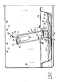
- the roast rack shown is intended to be placed in a roasting pan 10 (fig2) equipped with heating resistors 12 and a dish 14.
- This roasting rack comprises a horizontal spit 16 with a square section which is rotated about its axis (arrow F) by an electric motor (not shown) incorporated into the roasting pan, and which is adapted to receive a roasting piece 18 (fig. 1) held between two forks 19.
- a universal pan 20 is arranged under the spindle 16. This universal pan is fitted into the dish 14. It has inclined portions 22 extending from the edge 24 of this universal pan to a central flat bottom 26 for collecting cooking juices.
- the spindle 16 is rotatably mounted in two vertical supports 28 located on two opposite sides of the plate 14.
- the roast rack is equipped with an automatic sprinkler comprising two buckets 30 carried respectively by two arms 32 rotated by the spindle 16 and extending away from this spit. These buckets are adapted to take from the bottom 26 of the drip pan, at each turn, a certain amount of the cooking juice which falls from the roasting piece 18 and to pour this juice over this piece.
- Each bucket 30 is mounted so as to be able to make a limited angular pivoting about an axis parallel to the axis of rotation of the spindle 16 and distant from this axis of rotation.
- one of the ends 34 of the bucket support arm 32 is rotatably mounted about a pivot axis in a bearing 36 which extends parallel to the axis of rotation of the spindle 16 and which is carried by a flange 38 integral in rotation with this spindle, while the bucket 30 is rigidly fixed on the other end 40 of the arm 32, said rotary end 34 carrying a finger 42 oriented transversely to the pivot axis and extending between two spaced stops 44 and 46 which are integral with the flange 38 and with which finger 42 cooperates to limit pivoting.
- the finger 42 for limiting the pivoting is simply constituted by a section of this arm itself, this section 42 being for this purpose adjacent to the rotary end 34 and forming with this end a bend 48.
- the flange 38 has a central passage with a square section which is threaded on the spindle 16, which ensures the rotational drive of this flange with the spindle.
- the axial immobilization of this flask on the spindle is ensured by tightening a butterfly screw 50 screwed into a lug of this flange and which comes to hang on one of the lateral faces of the spindle.
- the stops 44 and 46 are constituted by spaced apart tabs integral with the flange 38 and oriented respectively in planes parallel to the axis of rotation of the spindle.
- the rotary end 34 of the arm 32 is trapped between the lug 44 and a counter plate 52 fixed to this lug and overlapping said rotary end 34: the lug 44 and the counter plate 52 thus together constitute the pivot bearing 36.
- the counter plate 52 is formed by an elastic metal blade, one end 54, located on one side of the rotating part 34, is applied and fixed by rivets 56 to the tab 44, and the other end of which 58, situated on the other side of the rotary part 34, is left free and has a raised edge 60 which can be grasped by hand to elastically separate this blade from the tab in view to extract the arm 32 from its bearing 36 by a lateral translational movement (arrow G in FIG. 3).
- the arms 32 are thus made removable from their support flange 38, this for cleaning or storage purposes for example.
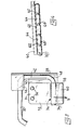
- Each bucket 30 has an elongated shape in a direction parallel to the direction of the spindle 16.
- the bottom of this bucket has a series of transverse internal ribs 62 (fig. 4) adapted to provide in this bottom a series of compartments 64 of distribution cooking juices.
- the shaft 32 comes to bear against the stop 46 by gravity, this up to the high position of the bucket illustrated in 30 'in FIG. 2.
- the bucket retains practically its full load without spillage, thanks to the angular delay of this bucket relative to the general rotational movement.
- the spill occurs in the upper part of the ascent path, that is to say on the upper part of the roasting piece 18, and not on the side thereof. It is only after having largely exceeded the top of the course that the arm 32 swings abruptly relative to the flange 38 in the direction of rotation to come into abutment against the second stop 44, position for which the bucket is ready for a new removal. in the drip pan 20.
Landscapes
- Engineering & Computer Science (AREA)
- Food Science & Technology (AREA)
- Baking, Grill, Roasting (AREA)
- Pharmaceuticals Containing Other Organic And Inorganic Compounds (AREA)
- Packages (AREA)
- Table Devices Or Equipment (AREA)
- Washing And Drying Of Tableware (AREA)
- Food-Manufacturing Devices (AREA)
- Massaging Devices (AREA)
- Liquid Crystal Substances (AREA)
- Transition And Organic Metals Composition Catalysts For Addition Polymerization (AREA)
- Polyesters Or Polycarbonates (AREA)
Abstract
Description
L'invention se rapporte à un porte-rôti adapté à équiper une rôtissoire et comprenant une broche horizontale destinée à être entrainée en rotation autour de son axe et adaptée à recevoir une pièce à rôtir, et une lèchefrite disposée sous cette broche pour recueillir le jus de cuisson.The invention relates to a roast rack adapted to equip a roasting pan and comprising a horizontal spit intended to be rotated about its axis and adapted to receive a part to be roasted, and a broiler pan placed under this spit to collect the juice Cooking.
L'invention concerne, plus précisément, un porte-rôti de ce genre qui comporte en outre un arroseur automatique comprenant au moins un godet porté par un bras entraîné en rotation par la broche et s'étendant à distance de cette broche, ce godet étant adapté à prélever dans la lèchefrite à chaque tour une certaine quantité de jus de cuisson et à déverser ce jus au-dessus de la pièce à rôtir.The invention relates more specifically to a roast rack of this kind which further comprises an automatic sprinkler comprising at least one bucket carried by an arm driven in rotation by the spindle and extending away from this spit, this bucket being suitable for taking a certain amount of cooking juices from the drip pan each time and pouring this juice over the roasting pan.
Pour que le godet accomplisse convenablement sa fonction de prélèvement du jus, il faut que son bord d'attaque vienne pratiquement râcler le fond de la lèchefrite. Malheureusement, dans les porte-rôti de ce genre, la position correcte de ce godet par rapport à la léchefrite ne peut généralement pas être rigoureusement assurée, non seulement en raison du manque de précision de la hauteur de la broche au-dessus de la lèchefrite, mais encore par suite du manque de rigidité du bras porte-godet qui, après plusieurs manipulations, peut être sujet à des déformations. Il s'ensuit que le godet risque, ou bien de venir buter contre le fond de la lèchefrite et d'arrêter ainsi le mouvement de rotation, ou alors de passer trop loin de ce fond et ne prélever donc qu'une trop faible quantité de jus.In order for the bucket to properly perform its juice collection function, its leading edge must practically scrape the bottom of the pan. Unfortunately, in roast dishes of this kind, the correct position of this bucket in relation to the drip pan cannot generally be rigorously ensured, not only due to the lack of precision in the height of the spit above the drip pan , but also due to the lack of rigidity of the bucket holder arm which, after several manipulations, may be subject to deformations. It follows that the bucket risks either coming up against the bottom of the drip pan and thus stopping the rotational movement, or else passing too far from this bottom and therefore only taking too little juice.
L'invention a pour but d'éliminer ces anomalies de fonctionnement.The object of the invention is to eliminate these operating anomalies.
Dans un porte-rôti selon l'invention, le godet est monté de manière à pouvoir effectuer un pivotement limité angulairement autour d'un axe parallèle à l'axe de rotation de la broche et distant de cet axe de rotation.In a roast rack according to the invention, the cup is mounted so as to be able to perform a limited angular pivoting about an axis parallel to the axis of rotation of the spit and distant from this axis of rotation.
Grâce à cette disposition, la distance entre l'axe de rotation de la broche et le bord d'attaque du godet peut varier dans certaines limites. Ainsi, si le bord d'attaque du godet vient momentanément buter sur le fond de la lèchefrite, le godet pivote légérement en sens inverse du mouvement de rotation de la broche, de sorte que la distance entre ledit bord d'attaque et l'axe de rotation de la broche diminue suffisamment pour permettre au godet de continuer son mouvement de rotation autour de l'axe de la broche avec râclement du bord d'attaque sur une zone du fond de la léchefrite.Thanks to this arrangement, the distance between the axis of rotation of the spindle and the leading edge of the bucket can vary within certain limits. Thus, if the leading edge of the bucket momentarily abuts on the bottom of the broiler pan, the bucket pivots slightly in the opposite direction to the spindle's rotational movement, so that the distance between said leading edge and the axis spindle rotation decreases enough to allow the bucket to continue its rotational movement around the spindle axis with scraping of the leading edge over an area in the bottom of the drip pan.
Les caractéristiques et avantages de l'invention ressortiront d'ailleurs de la description qui va suivre, à titre d'exempte, en référence aux dessins annexés dans lesquels:
- la figure 1 représente en perspective un porte-rôti selon l'invention; la figure 2 est une vue en coupe verticale selon la ligne II-II de la figure 1 ; la figure 3 représente l'articulation d'un bras porte-godets sur un flasque solidaire de la broche, vue en coupe selon la ligne III-III de la figure 2 ; la figure 4 est une coupe longitudinale d'un godet selon la ligne IV-IV de la figure 2.
- Figure 1 shows in perspective a roast rack according to the invention; Figure 2 is a vertical sectional view along line II-II of Figure 1; Figure 3 shows the articulation of a bucket holder arm on a flange secured to the spindle, sectional view along line III-III of Figure 2; FIG. 4 is a longitudinal section of a bucket along the line IV-IV of FIG. 2.
Le porte-rôti représenté est destiné à être placé dans une rôtissoire 10 (fig2) équipée de résistances chauffantes 12 et d'un plat 14. Ce porte-rôti comprend une broche horizontale 16 à section carrée qui est entraînée en rotation autour de son axe (flèche F) par un moteur électrique (non représenté) incorporé à la rôtissoire, et qui est adaptée à recevoir une pièce à rôtir 18 (fig. 1) maintenue entre deux fourches 19.The roast rack shown is intended to be placed in a roasting pan 10 (fig2) equipped with
Une lèchefrite 20 est disposée sous la broche 16. Cette lèchefrite est emboîtée dans le plat 14. Elle comporte des parties inclinées 22 s'étendant depuis le bord 24 de cette léchefrite jusqu'à un fond plan central 26 de collecte du jus de cuisson.A
La broche 16 est montée rotative dans deux supports verticaux 28 implantés sur deux côtés opposés du plat 14.The
Le porte-rôti est équipé d'un arroseur automatique comprenant deux godets 30 portés respectivement par deux bras 32 entrainés en rotation par la broche 16 et s'étendant à distance de cette broche. Ces godets sont adaptés à prélever dans le fond 26 de la léchefrite, à chaque tour, une certaine quantité du jus de cuisson qui tombe de la pièce à rôtir 18 et à déverser ce jus au-dessus de cette pièce.The roast rack is equipped with an automatic sprinkler comprising two
Chaque godet 30 est monté de manière à pouvoir effectuer un pivotement limité angulairement autour d'un axe parallèle à l'axe de rotation de la broche 16 et distant de cet axe de rotation. A cet effet, l'une des extrémités 34 du bras porte-godet 32 est montée rotative autour d'un axe de pivotement dans un palier 36 qui s'étend parallèlement à l'axe de rotation de la broche 16 et qui est porté par un flasque 38 solidaire en rotation de cette broche, tandis que le godet 30 est fixé rigidement sur l'autre extrémité 40 du bras 32, ladite extrémité rotative 34 portant un doigt 42 orienté transversalement à l'axe de pivotement et s'étendant entre deux butées espacées 44 et 46 qui sont solidaires du flasque 38 et avec lesquelles le doigt 42 coopère pour limiter le pivotement. Comme représenté clairement aux figures 1 à 3, le doigt 42 de limitation du pivotement est simplement constitué par un tronçon de ce bras lui-même, ce tronçon 42 étant à cet effet adjacent à l'extrémité rotative 34 et formant avec cette extrémité un coude 48.Each
Le flasque 38 présente un passage central à section carrée qui est enfilé sur la broche 16, ce qui assure l'entrainement en rotation de ce flasque avec la broche. L'immobilisation axiale de ce fiasque sur la broche est assurée par serrage d'une vis-papillon 50 vissée dans une patte de ce flasque et qui vient se bloquer sur l'une des faces latérales de la broche.The
Les butées 44 et 46 sont constituées par des pattes espacées solidaires du flasque 38 et orientées respectivement dans des plans parallèles à l'axe de rotation de la broche. L'extrémité rotative 34 du bras 32 est emprisonnée entre la patte 44 et une contre-plaque 52 fixée à cette patte et chevauchant ladite extrémité rotative 34 : la patte 44 et la contre-plaque 52 constituent ainsi ensemble le palier de pivotement 36. Comme on le voit bien sur les figures 2 et 3, la contre-plaque 52 est formée par une lame métallique élastique dont une extrémité 54, située d'un côté de la partie rotative 34, est appliquée et fixée par des rivets 56 à la patte 44, et dont l'autre extrémité 58, située de l'autre côté de la partie rotative 34, est laissée libre et présente un bord relevé 60 que l'on peut saisir à la main pour écarter élastiquement cette lame de la patte en vue d'extraire le bras 32 de son palier 36 par un mouvement de translation latérale (flèche G de la figure 3). Les bras 32 sont ainsi rendus amovibles de leur flasque de support 38, ceci à des fins de nettoyage ou de rangement par exemple.The
Chaque godet 30 présente une forme allongée dans une direction parallèlle à la direction de la broche 16. Le fond de ce godet présente une série de nervures internes transversales 62 (fig. 4) propres à ménager dans ce fond une série de compartiments 64 de répartition du jus de cuisson.Each
Comme on le comprend, si, lors de la rotation de la broche 16, le bord d'attaque 66 du godet 30 vient buter contre le fond 26 de la lèchefrite 20 - (fig.2), ce godet, alors que la rotation de la broche 16 se poursuit (flèche F), pivote d'abord légérement par rapport au flasque 38 (flèche H) en sens inverse du mouvement de rotation générale, de sorte que la distance entre le bord d'attaque 66 et l'axe de rotation de la broche diminue suffisamment pour permettre à ce godet de continuer son mouvement de rotation autour de l'axe de la broche avec râclement du bord d'attaque 66 sur une zone du fond de la lèchefrite.As will be understood, if, during the rotation of the
Après que l'opération de prélévement a été effectuée, l'arbre 32, dès le début de son mouvement de remontée (flèche K), vient en appui contre la butée 46 par effet de gravité, ceci jusqu'à la position haute du godet illustrée en 30' à la figure 2. Ainsi, pendant la plus grande partie du parcours de remontée, le godet conserve pratiquement sa pleine charge sans déversement, grâce au retard angulaire de ce godet par rapport au mouvement général de rotation. Le déversement se produit dans la partie supérieure du parcours de remontée, c'est-à-dire sur la partie supérieure de la pièce à rôtir 18, et non pas sur le côté de celle-ci. C'est seulement après avoir largement dépassé le sommet du parcours que le bras 32 bascule brusquement par rapport au flasque 38 dans le sens de la rotation pour venir en appui contre la seconde butée 44, position pour laquelle le godet est prêt à un nouveau prélévement dans la léchefrite 20.After the removal operation has been carried out, the
Comme il n'est pas possible, en raison de l'imprécision inévitable des relations géométriques entre la broche 16, le fond 26 de la léchefrite, les bras 32 et les godets 30, d'assurer un parallélisme rigoureux entre le godet 30 et le fond 26 de la léchefrite, il peut arriver que, lors du prélévement du jus de cuisson, ce jus ait tendance à se rassembler en l'une des extrémités du fond du godet, d'où il risque de s'ensuivre un arrosage mal distribué sur la pièce à rôtir 18. Le compartimentage du fond du godet ménagé par les nervures 62 limite cet inconvénient, c'est-à-dire assure, même lorsque le godet est légérement incliné sur l'horizontale (cômme illustré à la figure 4) une répartition plus régulière du jus (68) dans le godet, et partant un arrosage mieux distribué longitudinalement sur la pièce à rôtir.As it is not possible, due to the inevitable imprecision of the geometric relationships between the
Claims (8)
caractérisé en ce que l'une des extrémités (34) du bras porte-godet (32) est montée rotative autour d'un axe de pivotement dans un palier (36) qui s'étend parallélement à l'axe de rotation de la broche (16) et qui est porté par un flasque (38) solidaire en rotation de cette broche, tandis que le godet (30) est fixé rigidement sur l'autre extrémité - (40) dudit bras (32), ladite extrémité rotative (34) du bras (32) portant un doigt (42) s'étendant entre deux butées espacées (44 et 46) qui sont solidaires du flasque (38) et avec lesquelles ce doigt (42) coopère pour limiter le pivotement.2. Roast rack according to claim 1,
characterized in that one of the ends (34) of the bucket support arm (32) is rotatably mounted about a pivot axis in a bearing (36) which extends parallel to the axis of rotation of the spindle (16) and which is carried by a flange (38) integral in rotation with this spindle, while the bucket (30) is rigidly fixed on the other end - (40) of said arm (32), said rotary end (34 ) of the arm (32) carrying a finger (42) extending between two spaced stops (44 and 46) which are integral with the flange (38) and with which this finger (42) cooperates to limit pivoting.
caractérisé en ce que le bras (32) est monté amovible sur le flasque (38).3. Roast rack according to claim 2,
characterized in that the arm (32) is removably mounted on the flange (38).
caractérisé en ce que, l'une au moins des butées étant constituée par une patte (44) solidaire du flasque (38) et orientée dans un plan parallèle à l'axe de rotation de la broche (16), l'extrémité rotative (34) du bras est emprisonnèe entre cette patte (44) et une contreplaque (52) fixée à cette patte et chevauchant ladite extrémité rotative (34), la patte - (44) et la contre-plaque (52) constituant ainsi ensemble le palier (36) de pivotement du bras (32).4. Roast rack according to claim 2 or claim 3,
characterized in that, at least one of the stops being constituted by a tab (44) integral with the flange (38) and oriented in a plane parallel to the axis of rotation of the spindle (16), the rotary end ( 34) of the arm is trapped between this lug (44) and a plywood (52) fixed to this lug and overlapping said rotary end (34), the lug - (44) and the counterplate (52) thus together constituting the bearing (36) pivoting of the arm (32).
caractérisé en ce que la contre-plaque (52) est constituée par une lame élastique dont une extrémité (54), située d'un côté de l'extrémité rotative (34) du bras (32), est appliquée et fixée à la patte (44), et dont l'autre extrémité (58), située de l'autre côté de l'extrémité rotative (34), est libre, et présente un bord relevé (60) que l'on peut saisir à la main pour écarter cette lame (52) de la patte - (44) en vue d'extraire le bras de son palier (36) par un mouvement de translation latérale.5. Roast rack according to claims 3 and 4,
characterized in that the counterplate (52) consists of an elastic blade, one end (54) of which is situated on one side of the rotary end (34) of the arm (32), is applied and fixed to the tab (44), and whose other end (58), located on the other side of the rotary end (34), is free, and has a raised edge (60) which can be grasped by hand to move this blade (52) away from the tab - (44) in order to extract the arm from its bearing (36) by a movement of lateral translation.
caractérisé en ce que le doigt (42) de limitation du pivotement est constitué par un tronçon du bras (32) lui-même, ce tronçon (42) étant adjacent à l'extrémité rotative (34) de ce bras et formant un coude (48) avec cette extrémité (34).6. Roast rack according to any one of claims 2 to 5,
characterized in that the pivoting limitation finger (42) consists of a section of the arm (32) itself, this section (42) being adjacent to the rotary end (34) of this arm and forming a bend ( 48) with this end (34).
caractérisé en ce que, le godet (30) présentant une forme allongée dans une direction parallèle à la direction de la broche (16), le fond de ce godet présente une série de nervures internes transver- " sales (62) propres à ménager dans ce fond une série de compartiments (64) de répartition du jus de cuisson.7. Roast rack according to any one of the preceding claims,
characterized in that, the cup (30) having an elongated shape in a direction parallel to the direction of the spindle (16), the bottom of this cup has a series of internal transverse ribs (62) suitable for accommodating in this bottom a series of compartments (64) for distributing the cooking juice.
caractérisé en ce que la léchefrite (20) comprend des parties inclinées (22) s'étendant depuis le bord (24) de cette lèchefrite jusqu'à un fond plan central (26) de collecte du jus.8. Roast rack according to any one of the preceding claims,
characterized in that the drip pan (20) comprises inclined parts (22) extending from the edge (24) of this drip pan to a central flat bottom (26) for collecting the juice.
Priority Applications (1)
| Application Number | Priority Date | Filing Date | Title |
|---|---|---|---|
| AT86106065T ATE35893T1 (en) | 1985-05-03 | 1986-05-02 | FRYING INSERT FOR GRILLING DEVICE. |
Applications Claiming Priority (2)
| Application Number | Priority Date | Filing Date | Title |
|---|---|---|---|
| FR8506764 | 1985-05-03 | ||
| FR8506764A FR2581305B1 (en) | 1985-05-03 | 1985-05-03 | ROTISSERIE FOR ROTISSERIE |
Publications (2)
| Publication Number | Publication Date |
|---|---|
| EP0200233A1 true EP0200233A1 (en) | 1986-11-05 |
| EP0200233B1 EP0200233B1 (en) | 1988-07-27 |
Family
ID=9318937
Family Applications (1)
| Application Number | Title | Priority Date | Filing Date |
|---|---|---|---|
| EP86106065A Expired EP0200233B1 (en) | 1985-05-03 | 1986-05-02 | Food tray for grilling device |
Country Status (6)
| Country | Link |
|---|---|
| EP (1) | EP0200233B1 (en) |
| AT (1) | ATE35893T1 (en) |
| DE (1) | DE3660410D1 (en) |
| ES (1) | ES293919Y (en) |
| FR (1) | FR2581305B1 (en) |
| PT (1) | PT82497B (en) |
Cited By (3)
| Publication number | Priority date | Publication date | Assignee | Title |
|---|---|---|---|---|
| WO2007080035A2 (en) * | 2006-01-10 | 2007-07-19 | BSH Bosch und Siemens Hausgeräte GmbH | Cooking device and method for basting an item to be cooked |
| EP2147601A1 (en) * | 2008-07-24 | 2010-01-27 | Fagor, S. Coop. | Tool for making bread for a household oven |
| EP2799779A3 (en) * | 2013-04-30 | 2015-12-23 | Dongbu Daewoo Electronics Corporation | Cooking apparatus |
Citations (7)
| Publication number | Priority date | Publication date | Assignee | Title |
|---|---|---|---|---|
| US2182225A (en) * | 1938-06-27 | 1939-12-05 | Gus G Garvis | Barbecue machine |
| FR1099625A (en) * | 1954-02-18 | 1955-09-07 | Diffusion De Materiel Electr S | Device for basting a roast during cooking in an electric roasting pan |
| FR68137E (en) * | 1955-07-06 | 1958-04-08 | Alliages Legers De Paris Zeppe | Spit |
| US2885951A (en) * | 1957-10-08 | 1959-05-12 | Whirlpool Co | Rotisserie with automatic basting mechanism |
| FR77639E (en) * | 1960-04-30 | 1962-03-30 | Roasting pan | |
| GB946355A (en) * | 1961-12-14 | 1964-01-08 | Parkinson Cowan Appliances Ltd | Improvements relating to spit roasters |
| FR1460331A (en) * | 1965-12-17 | 1966-11-25 | Cadillac France | Improvements to skewers for rotisseries and other cooking appliances |
-
1985
- 1985-05-03 FR FR8506764A patent/FR2581305B1/en not_active Expired - Fee Related
-
1986
- 1986-04-30 ES ES1986293919U patent/ES293919Y/en not_active Expired
- 1986-05-02 AT AT86106065T patent/ATE35893T1/en not_active IP Right Cessation
- 1986-05-02 PT PT82497A patent/PT82497B/en not_active IP Right Cessation
- 1986-05-02 EP EP86106065A patent/EP0200233B1/en not_active Expired
- 1986-05-02 DE DE8686106065T patent/DE3660410D1/en not_active Expired
Patent Citations (7)
| Publication number | Priority date | Publication date | Assignee | Title |
|---|---|---|---|---|
| US2182225A (en) * | 1938-06-27 | 1939-12-05 | Gus G Garvis | Barbecue machine |
| FR1099625A (en) * | 1954-02-18 | 1955-09-07 | Diffusion De Materiel Electr S | Device for basting a roast during cooking in an electric roasting pan |
| FR68137E (en) * | 1955-07-06 | 1958-04-08 | Alliages Legers De Paris Zeppe | Spit |
| US2885951A (en) * | 1957-10-08 | 1959-05-12 | Whirlpool Co | Rotisserie with automatic basting mechanism |
| FR77639E (en) * | 1960-04-30 | 1962-03-30 | Roasting pan | |
| GB946355A (en) * | 1961-12-14 | 1964-01-08 | Parkinson Cowan Appliances Ltd | Improvements relating to spit roasters |
| FR1460331A (en) * | 1965-12-17 | 1966-11-25 | Cadillac France | Improvements to skewers for rotisseries and other cooking appliances |
Cited By (4)
| Publication number | Priority date | Publication date | Assignee | Title |
|---|---|---|---|---|
| WO2007080035A2 (en) * | 2006-01-10 | 2007-07-19 | BSH Bosch und Siemens Hausgeräte GmbH | Cooking device and method for basting an item to be cooked |
| WO2007080035A3 (en) * | 2006-01-10 | 2007-09-07 | Bsh Bosch Siemens Hausgeraete | Cooking device and method for basting an item to be cooked |
| EP2147601A1 (en) * | 2008-07-24 | 2010-01-27 | Fagor, S. Coop. | Tool for making bread for a household oven |
| EP2799779A3 (en) * | 2013-04-30 | 2015-12-23 | Dongbu Daewoo Electronics Corporation | Cooking apparatus |
Also Published As
| Publication number | Publication date |
|---|---|
| FR2581305A1 (en) | 1986-11-07 |
| ES293919U (en) | 1986-12-16 |
| EP0200233B1 (en) | 1988-07-27 |
| PT82497A (en) | 1986-06-01 |
| ATE35893T1 (en) | 1988-08-15 |
| ES293919Y (en) | 1987-08-01 |
| PT82497B (en) | 1992-07-31 |
| DE3660410D1 (en) | 1988-09-01 |
| FR2581305B1 (en) | 1990-05-18 |
Similar Documents
| Publication | Publication Date | Title |
|---|---|---|
| CA2162144C (en) | Device for automatically rotating rotisserie skewers | |
| EP2651271B1 (en) | Food cooking appliance comprising a stirring blade | |
| EP0191161B1 (en) | Electric household apparatus for preparing food like sauces or creams | |
| CH669099A5 (en) | APPARATUS FOR COOKING TWO SIDES. | |
| EP0776624A1 (en) | Electrical barbecue with a frying appliance | |
| EP1978855A1 (en) | Cooking appliance with stirring means and associated method | |
| FR2892008A3 (en) | RECLINING APPARATUS OR RECLINING COOKER | |
| EP0737435A1 (en) | Culinary receptacle with a lid provided with a pouring function | |
| FR3034972A3 (en) | GRILL KIT | |
| EP0200233B1 (en) | Food tray for grilling device | |
| EP0081466B1 (en) | Cheese grating apparatus | |
| FR2726456A1 (en) | DEVICE FOR LOCKING A TANK ON A MOTOR SUPPORT FOR A FOOD PREPARATION APPARATUS | |
| EP3079542A1 (en) | Household food preparation appliance comprising a lower arm borne by a base and an upper arm connected to the lower arm by a hinge means | |
| FR2712791A1 (en) | Cooking installation and basket for such an installation. | |
| EP2564734B1 (en) | Cooking device | |
| CH469475A (en) | Roasting pan | |
| EP1479330B1 (en) | Household appliance with two offset articulated hot plates | |
| EP2422668B1 (en) | Cooking utensil with induction bottom and juice draining | |
| FR2611477A2 (en) | CHICKEN COOKING DEVICE WITH ROTATION DRIVE AND AUTOMATIC BREWING | |
| FR2858199A1 (en) | Tippable cooking pot has shafts on either side which fit into bores in supports, stops mounted in recesses in supports limiting degree of tipping of pot | |
| FR2724305A1 (en) | Rod on plate to hold skewer for meat | |
| BE1009202A6 (en) | Basket for cooking device. | |
| FR2650373A1 (en) | Cover for hot plate which can be built into the tops of kitchen cabinets | |
| FR3110367A1 (en) | Food cooking appliance comprising a removable cooking bowl. | |
| EP1444941A1 (en) | Grilling device of the raclette type |
Legal Events
| Date | Code | Title | Description |
|---|---|---|---|
| PUAI | Public reference made under article 153(3) epc to a published international application that has entered the european phase |
Free format text: ORIGINAL CODE: 0009012 |
|
| 17P | Request for examination filed |
Effective date: 19860929 |
|
| AK | Designated contracting states |
Kind code of ref document: A1 Designated state(s): AT BE CH DE GB IT LI NL SE |
|
| PUAB | Information related to the publication of an a document modified or deleted |
Free format text: ORIGINAL CODE: 0009199EPPU |
|
| PUAF | Information related to the publication of a search report (a3 document) modified or deleted |
Free format text: ORIGINAL CODE: 0009199SEPU |
|
| R17D | Deferred search report published (corrected) |
Effective date: 19861210 |
|
| RA1 | Application published (corrected) |
Date of ref document: 19861210 Kind code of ref document: A1 |
|
| 17Q | First examination report despatched |
Effective date: 19870421 |
|
| GRAA | (expected) grant |
Free format text: ORIGINAL CODE: 0009210 |
|
| AK | Designated contracting states |
Kind code of ref document: B1 Designated state(s): AT BE CH DE GB IT LI NL SE |
|
| REF | Corresponds to: |
Ref document number: 35893 Country of ref document: AT Date of ref document: 19880815 Kind code of ref document: T |
|
| GBT | Gb: translation of ep patent filed (gb section 77(6)(a)/1977) | ||
| REF | Corresponds to: |
Ref document number: 3660410 Country of ref document: DE Date of ref document: 19880901 |
|
| ITF | It: translation for a ep patent filed | ||
| PLBE | No opposition filed within time limit |
Free format text: ORIGINAL CODE: 0009261 |
|
| STAA | Information on the status of an ep patent application or granted ep patent |
Free format text: STATUS: NO OPPOSITION FILED WITHIN TIME LIMIT |
|
| 26N | No opposition filed | ||
| ITTA | It: last paid annual fee | ||
| PGFP | Annual fee paid to national office [announced via postgrant information from national office to epo] |
Ref country code: AT Payment date: 19930514 Year of fee payment: 8 |
|
| PGFP | Annual fee paid to national office [announced via postgrant information from national office to epo] |
Ref country code: CH Payment date: 19930518 Year of fee payment: 8 |
|
| PG25 | Lapsed in a contracting state [announced via postgrant information from national office to epo] |
Ref country code: AT Effective date: 19940502 |
|
| PG25 | Lapsed in a contracting state [announced via postgrant information from national office to epo] |
Ref country code: LI Effective date: 19940531 Ref country code: CH Effective date: 19940531 |
|
| EAL | Se: european patent in force in sweden |
Ref document number: 86106065.5 |
|
| REG | Reference to a national code |
Ref country code: CH Ref legal event code: PL |
|
| PGFP | Annual fee paid to national office [announced via postgrant information from national office to epo] |
Ref country code: DE Payment date: 19960503 Year of fee payment: 11 |
|
| PG25 | Lapsed in a contracting state [announced via postgrant information from national office to epo] |
Ref country code: DE Free format text: LAPSE BECAUSE OF NON-PAYMENT OF DUE FEES Effective date: 19980203 |
|
| PGFP | Annual fee paid to national office [announced via postgrant information from national office to epo] |
Ref country code: SE Payment date: 19980518 Year of fee payment: 13 |
|
| PGFP | Annual fee paid to national office [announced via postgrant information from national office to epo] |
Ref country code: BE Payment date: 19980709 Year of fee payment: 13 |
|
| PG25 | Lapsed in a contracting state [announced via postgrant information from national office to epo] |
Ref country code: SE Free format text: LAPSE BECAUSE OF NON-PAYMENT OF DUE FEES Effective date: 19990503 |
|
| PG25 | Lapsed in a contracting state [announced via postgrant information from national office to epo] |
Ref country code: BE Free format text: LAPSE BECAUSE OF NON-PAYMENT OF DUE FEES Effective date: 19990531 |
|
| BERE | Be: lapsed |
Owner name: MOULINEX Effective date: 19990531 |
|
| EUG | Se: european patent has lapsed |
Ref document number: 86106065.5 |
|
| PGFP | Annual fee paid to national office [announced via postgrant information from national office to epo] |
Ref country code: GB Payment date: 20010502 Year of fee payment: 16 |
|
| PGFP | Annual fee paid to national office [announced via postgrant information from national office to epo] |
Ref country code: NL Payment date: 20010531 Year of fee payment: 16 |
|
| REG | Reference to a national code |
Ref country code: GB Ref legal event code: IF02 |
|
| PG25 | Lapsed in a contracting state [announced via postgrant information from national office to epo] |
Ref country code: GB Free format text: LAPSE BECAUSE OF NON-PAYMENT OF DUE FEES Effective date: 20020502 |
|
| PG25 | Lapsed in a contracting state [announced via postgrant information from national office to epo] |
Ref country code: NL Free format text: LAPSE BECAUSE OF NON-PAYMENT OF DUE FEES Effective date: 20021201 |
|
| GBPC | Gb: european patent ceased through non-payment of renewal fee |
Effective date: 20020502 |
|
| NLV4 | Nl: lapsed or anulled due to non-payment of the annual fee |
Effective date: 20021201 |
|
| PG25 | Lapsed in a contracting state [announced via postgrant information from national office to epo] |
Ref country code: IT Free format text: LAPSE BECAUSE OF NON-PAYMENT OF DUE FEES;WARNING: LAPSES OF ITALIAN PATENTS WITH EFFECTIVE DATE BEFORE 2007 MAY HAVE OCCURRED AT ANY TIME BEFORE 2007. THE CORRECT EFFECTIVE DATE MAY BE DIFFERENT FROM THE ONE RECORDED. Effective date: 20050502 |