EP0200205B1 - Kupplung um zwei gleichachsige Wellen zu kuppeln mit teleskopischem Zwischenteil - Google Patents
Kupplung um zwei gleichachsige Wellen zu kuppeln mit teleskopischem Zwischenteil Download PDFInfo
- Publication number
- EP0200205B1 EP0200205B1 EP19860105896 EP86105896A EP0200205B1 EP 0200205 B1 EP0200205 B1 EP 0200205B1 EP 19860105896 EP19860105896 EP 19860105896 EP 86105896 A EP86105896 A EP 86105896A EP 0200205 B1 EP0200205 B1 EP 0200205B1
- Authority
- EP
- European Patent Office
- Prior art keywords
- gear
- clutch
- sliding part
- shafts
- shaft
- Prior art date
- Legal status (The legal status is an assumption and is not a legal conclusion. Google has not performed a legal analysis and makes no representation as to the accuracy of the status listed.)
- Expired
Links
- 230000008878 coupling Effects 0.000 claims description 18
- 238000010168 coupling process Methods 0.000 claims description 18
- 238000005859 coupling reaction Methods 0.000 claims description 18
- 239000000969 carrier Substances 0.000 claims description 12
- 230000001360 synchronised effect Effects 0.000 claims description 5
- 230000005540 biological transmission Effects 0.000 description 6
- 238000010276 construction Methods 0.000 description 2
- 244000145845 chattering Species 0.000 description 1
- 238000006073 displacement reaction Methods 0.000 description 1
- 210000000056 organ Anatomy 0.000 description 1
- 230000002028 premature Effects 0.000 description 1
Images
Classifications
-
- F—MECHANICAL ENGINEERING; LIGHTING; HEATING; WEAPONS; BLASTING
- F16—ENGINEERING ELEMENTS AND UNITS; GENERAL MEASURES FOR PRODUCING AND MAINTAINING EFFECTIVE FUNCTIONING OF MACHINES OR INSTALLATIONS; THERMAL INSULATION IN GENERAL
- F16D—COUPLINGS FOR TRANSMITTING ROTATION; CLUTCHES; BRAKES
- F16D23/00—Details of mechanically-actuated clutches not specific for one distinct type
- F16D23/02—Arrangements for synchronisation, also for power-operated clutches
Definitions
- the present invention relates to a clutch allowing the coupling of two coaxial shafts by a sliding intermediate piece, each shaft being provided at its end with a pinion, said sliding intermediate piece being in permanent engagement with the pinion of one of the shafts and sliding, by mechanical means on the pinion of the other shaft at the time of coupling.
- this type of mechanical coupling is used to transmit high powers from one tree to another, for example, for the propulsion of ships.
- a synchronous clutch is used, but since this does not allow the transmission of high powers, it is necessary, after the coupling of the two shafts, that it no longer participates in the transmission of power.
- Synchronous clutches which make it possible to bring two shafts at the same speed and no longer participate in the transmission of power after coupling, but these clutches functioning as a free wheel, using pawls, require the two shafts to turn each in the same direction, not to change the direction of rotation of the assembly nor to change the function of each tree, that is to say that the driving tree cannot become led and vice versa.
- French patent 1541874 describes a coupling mechanism of the above type which includes a friction clutch system in which, by means of a double gear train of very similar but not identical ratio, the '' receiving shaft at a speed very close to but not equal to that of the motor shaft, which allows, thanks to the slight sliding speed of one shaft relative to the other, to actuate the sliding intermediate piece which engages when the teeth are aligned.
- a friction clutch system in which, by means of a double gear train of very similar but not identical ratio, the '' receiving shaft at a speed very close to but not equal to that of the motor shaft, which allows, thanks to the slight sliding speed of one shaft relative to the other, to actuate the sliding intermediate piece which engages when the teeth are aligned.
- Such a device is not desirable for very large couples because there is a risk of chattering causing premature wear or even rupture of the teeth.
- the pinions of the gear trains although no longer participating in the transmission, continue to rotate which is the source of unnecessary or harmful noise.
- the clutch according to the present invention allows the smooth and quieter coupling of two shafts, regardless of the direction of rotation of these two shafts, the direction of rotation chosen once the coupling has been made and the driving character or led by everyone.
- the clutch according to the invention is characterized in that it comprises two movable planet carriers each provided with a brake and at least three satellites, and a common central planetary gear meshing with the satellites of the two planet carriers , the satellites of one of the planet carriers further meshing inside a toothed ring secured to the shaft provided with a pinion receiving the intermediate sliding part at the time of coupling and the satellites of the another planet carrier further meshing inside a ring gear secured to the sliding part, the gear ratios being chosen so that the respective speeds of the two coaxial shafts to be coupled are synchronous when the two carriers satellites are immobilized.
- the mechanical means of displacement of the sliding part is a stationary ring in rotation, and each brake is made up of jaws and of a disc secured to a planet carrier.
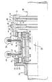
- the single figure shows a sectional view of the clutch and the coupling.
- a shaft 10 comprising a pinion 11 provided with a toothing 12 over its entire circumference, a shaft 20 also comprising a pinion 21 provided with a toothing 22 over its entire circumference and a sliding intermediate piece 30 comprising a ring gear 31 provided with a toothing 32.
- the toothing 12 of the pinion 11 being permanently engaged with the toothing 32 of the sliding intermediate piece 30, the mechanical coupling consists in moving, according to the arrow, this sliding piece 30 to bring its teeth 32 into engagement with the teeth 22 of the pinion 21.
- This sliding part 30 is moved axially by a ring 70 fixed in rotation, itself moved by any mechanical means, such as a fork for example.
- a clutch which is made up of two planet carriers 42, 52 respectively rotating in a guide bearing 41, 51.
- Each planet carrier 42, 52 respectively comprises at least three axes 43, 53 distributed circumferentially and on which rotates a satellite pinion 44, 54 provided with a toothing 46, 56, a brake disc 47, 57 and associated jaws 48, 58, each disc being of course secured to a door -satellites.
- This clutch also includes a common central planetary gear 60 provided at each of its ends with teeth 66A, 66B. a crown 25, provided with a toothing 26, secured to a plate 24 itself secured to the shaft 20, and another crown 35, provided with a toothing 36, forming part of the sliding part 30.
- the satellites 44 of the planet carrier 42 roll in the teeth 26 of the crown 25, and the satellites 54 of the planet carrier 52 roll in the teeth 36 of the crown 35.
- teeth 26 and 36 of the toothed crowns 25 and 35 it is possible to make the teeth 26 and 36 of the toothed crowns 25 and 35 to a different diameter of the teeth 32 of the part 30, with the same number of teeth but with a different modulus, or with a multiple or submultiple number of teeth.
- the jaws 58 are tightened to block the planet carrier 52.
- the toothing 36 of the crown 30 rotates about the axes 53 the satellites 54 and themselves rotate the central pinion 60 by means of its toothing 66A, in a direction of rotation opposite to that of the shaft 10.
- the jaws 48 are then tightened to block the planet carrier 42.
- the toothing 66B of the planetary pinion 60 drives, in rotation about the axes 43, the planet gears 44 and themselves then rotates in the same direction the crown 25 of tree 20.
- the shafts 10, 20 rotate at the same speed, in the same direction, only the central planetary gear 60 rotating in the opposite direction. It is then possible to move the sliding part 30 to bring its toothing 32 into engagement with the toothing 22 of the shaft 20.
- the toothing 22 and 26 are aligned, the toothing 66A and 66B also being aligned and having chosen the same number of teeth for the teeth 26, 36, the teeth 26 and 36 are then aligned and therefore also the teeth 22 and 36.
- a tooth 32 is aligned with the gap between two teeth 36 of the crown 35. As 22 is aligned with 36, 22 is therefore aligned with 12 and therefore aligned in the interval between two teeth 32 of the crown 31.
- the coupling is then possible by moving the part 30 using the ring 70.
Landscapes
- Engineering & Computer Science (AREA)
- General Engineering & Computer Science (AREA)
- Mechanical Engineering (AREA)
- Mechanical Operated Clutches (AREA)
Claims (3)
Applications Claiming Priority (2)
| Application Number | Priority Date | Filing Date | Title |
|---|---|---|---|
| FR8506573 | 1985-04-30 | ||
| FR8506573A FR2581145B1 (fr) | 1985-04-30 | 1985-04-30 | Embrayage synchrone permettant l'accouplement de deux arbres coaxiaux par une piece intermediaire coulissante. |
Publications (2)
| Publication Number | Publication Date |
|---|---|
| EP0200205A1 EP0200205A1 (de) | 1986-11-05 |
| EP0200205B1 true EP0200205B1 (de) | 1989-01-11 |
Family
ID=9318833
Family Applications (1)
| Application Number | Title | Priority Date | Filing Date |
|---|---|---|---|
| EP19860105896 Expired EP0200205B1 (de) | 1985-04-30 | 1986-04-29 | Kupplung um zwei gleichachsige Wellen zu kuppeln mit teleskopischem Zwischenteil |
Country Status (3)
| Country | Link |
|---|---|
| EP (1) | EP0200205B1 (de) |
| DE (1) | DE3661764D1 (de) |
| FR (1) | FR2581145B1 (de) |
Families Citing this family (1)
| Publication number | Priority date | Publication date | Assignee | Title |
|---|---|---|---|---|
| CN109356982B (zh) * | 2018-10-16 | 2020-06-12 | 东风汽车集团有限公司 | 行星减速换挡机构及汽车 |
Family Cites Families (4)
| Publication number | Priority date | Publication date | Assignee | Title |
|---|---|---|---|---|
| FR816487A (fr) * | 1936-04-15 | 1937-08-09 | Andre Citroe N | Dispositif pour déceler l'instant où deux organes mobiles ont des vitesses synchrones et pour commander leur couplage, dit contact synchroniseur |
| US3468178A (en) * | 1966-10-26 | 1969-09-23 | Mitsubishi Heavy Ind Ltd | Interlocking arrangement for rotating shafts |
| FR1541874A (fr) * | 1967-10-25 | 1968-10-11 | Mitsubishi Heavy Ind Ltd | Mécanisme d'embrayage à synchronisation |
| FR2487937A1 (fr) * | 1980-08-01 | 1982-02-05 | Lacour Jean | Ajusteur de rapport de vitesses |
-
1985
- 1985-04-30 FR FR8506573A patent/FR2581145B1/fr not_active Expired
-
1986
- 1986-04-29 DE DE8686105896T patent/DE3661764D1/de not_active Expired
- 1986-04-29 EP EP19860105896 patent/EP0200205B1/de not_active Expired
Also Published As
| Publication number | Publication date |
|---|---|
| EP0200205A1 (de) | 1986-11-05 |
| FR2581145B1 (fr) | 1989-10-20 |
| FR2581145A1 (fr) | 1986-10-31 |
| DE3661764D1 (en) | 1989-02-16 |
Similar Documents
| Publication | Publication Date | Title |
|---|---|---|
| WO2001065152A1 (fr) | Dispositif de transmission automatise a engrenages, en particulier pour vehicule automobile | |
| FR2817009A1 (fr) | Dispositif de transmission, notamment pour vehicule terrestre | |
| EP1273825B1 (de) | Getriebe mit parallelen Wellen und Verfahren zur Steuerung der Schaltungen | |
| FR2625278A1 (fr) | Actionneur pour dispositif de mise en prise a friction | |
| EP0948721B1 (de) | Wechselgetriebe mit synchronisiertem rückwärtsgang für kraftfahrzeuge | |
| FR2959543A1 (fr) | Dispositif de synchronisation freinant les arbres d'une boite de vitesses pour l'engagement de la marche arriere, et boite de vitesses correspondante | |
| EP0200205B1 (de) | Kupplung um zwei gleichachsige Wellen zu kuppeln mit teleskopischem Zwischenteil | |
| EP0041730B1 (de) | Gangschaltgetriebe mit vier Vorwärts- und zwei Rückwärtsgängen | |
| FR2702814A1 (fr) | Transmission automatique à vitesse variable. | |
| FR2698144A1 (fr) | Boîte de vitesses munie de trois transmissions partielles à trains planétaires. | |
| EP0369900B1 (de) | Zweistufiges Getriebe mit Gangwechsel im Stillstand | |
| FR2501621A1 (fr) | Perfectionnements aux systemes moteurs pour bateaux susceptibles de passer de la marche a grande vitesse a celle a vitesse reduite | |
| EP0014139A2 (de) | Stufenloses Wechselgetriebe | |
| FR2673450A1 (fr) | Boite de vitesses manóoeuvrable sous charge. | |
| FR2841956A1 (fr) | Vehicule automobile a roue libre sur le pignon recepteur de premiere | |
| FR2897134A1 (fr) | Groupe motopropulseur hybride optimise pour l'engagement de la premiere vitesse et de la marche arriere | |
| BE409753A (de) | ||
| FR2789742A1 (fr) | Boite de vitesses notamment pour vehicules automobiles | |
| FR3115085A1 (fr) | Transmission à arbre et crabot liés par filetage | |
| FR2540209A1 (fr) | Transmission a engrenages, en particulier pour turbine a arbre libre | |
| WO2002021016A1 (fr) | Dispositif de transmission, notamment pour l'automobile | |
| BE522058A (de) | ||
| FR3024515A1 (fr) | Variateur de couple a disques | |
| FR3010166A1 (fr) | Transmission a variation continue avec recirculation de puissance | |
| FR2638500A1 (fr) | Differentiel autobloquant a train epicycloidal |
Legal Events
| Date | Code | Title | Description |
|---|---|---|---|
| PUAI | Public reference made under article 153(3) epc to a published international application that has entered the european phase |
Free format text: ORIGINAL CODE: 0009012 |
|
| AK | Designated contracting states |
Kind code of ref document: A1 Designated state(s): CH DE FR GB IT LI NL |
|
| 17P | Request for examination filed |
Effective date: 19870504 |
|
| 17Q | First examination report despatched |
Effective date: 19880330 |
|
| GRAA | (expected) grant |
Free format text: ORIGINAL CODE: 0009210 |
|
| AK | Designated contracting states |
Kind code of ref document: B1 Designated state(s): CH DE FR GB IT LI NL |
|
| GBT | Gb: translation of ep patent filed (gb section 77(6)(a)/1977) | ||
| REF | Corresponds to: |
Ref document number: 3661764 Country of ref document: DE Date of ref document: 19890216 |
|
| ITF | It: translation for a ep patent filed | ||
| PLBE | No opposition filed within time limit |
Free format text: ORIGINAL CODE: 0009261 |
|
| STAA | Information on the status of an ep patent application or granted ep patent |
Free format text: STATUS: NO OPPOSITION FILED WITHIN TIME LIMIT |
|
| 26N | No opposition filed | ||
| ITTA | It: last paid annual fee | ||
| PGFP | Annual fee paid to national office [announced via postgrant information from national office to epo] |
Ref country code: CH Payment date: 19950103 Year of fee payment: 10 |
|
| PGFP | Annual fee paid to national office [announced via postgrant information from national office to epo] |
Ref country code: GB Payment date: 19960212 Year of fee payment: 11 |
|
| PG25 | Lapsed in a contracting state [announced via postgrant information from national office to epo] |
Ref country code: LI Effective date: 19960430 Ref country code: CH Effective date: 19960430 |
|
| PGFP | Annual fee paid to national office [announced via postgrant information from national office to epo] |
Ref country code: NL Payment date: 19960430 Year of fee payment: 11 |
|
| REG | Reference to a national code |
Ref country code: CH Ref legal event code: PL |
|
| PGFP | Annual fee paid to national office [announced via postgrant information from national office to epo] |
Ref country code: FR Payment date: 19970314 Year of fee payment: 12 |
|
| PGFP | Annual fee paid to national office [announced via postgrant information from national office to epo] |
Ref country code: DE Payment date: 19970320 Year of fee payment: 12 |
|
| PG25 | Lapsed in a contracting state [announced via postgrant information from national office to epo] |
Ref country code: GB Effective date: 19970429 |
|
| PG25 | Lapsed in a contracting state [announced via postgrant information from national office to epo] |
Ref country code: NL Effective date: 19971101 |
|
| GBPC | Gb: european patent ceased through non-payment of renewal fee |
Effective date: 19970429 |
|
| NLV4 | Nl: lapsed or anulled due to non-payment of the annual fee |
Effective date: 19971101 |
|
| PG25 | Lapsed in a contracting state [announced via postgrant information from national office to epo] |
Ref country code: FR Free format text: THE PATENT HAS BEEN ANNULLED BY A DECISION OF A NATIONAL AUTHORITY Effective date: 19980430 |
|
| PG25 | Lapsed in a contracting state [announced via postgrant information from national office to epo] |
Ref country code: DE Free format text: LAPSE BECAUSE OF NON-PAYMENT OF DUE FEES Effective date: 19990202 |
|
| REG | Reference to a national code |
Ref country code: FR Ref legal event code: ST |
|
| PG25 | Lapsed in a contracting state [announced via postgrant information from national office to epo] |
Ref country code: IT Free format text: LAPSE BECAUSE OF NON-PAYMENT OF DUE FEES;WARNING: LAPSES OF ITALIAN PATENTS WITH EFFECTIVE DATE BEFORE 2007 MAY HAVE OCCURRED AT ANY TIME BEFORE 2007. THE CORRECT EFFECTIVE DATE MAY BE DIFFERENT FROM THE ONE RECORDED. Effective date: 20050429 |