EP0200139A2 - Antriebsvorrichtung für ein, um eine horizontale Mittelachse schwingendes Tor - Google Patents
Antriebsvorrichtung für ein, um eine horizontale Mittelachse schwingendes Tor Download PDFInfo
- Publication number
- EP0200139A2 EP0200139A2 EP86105503A EP86105503A EP0200139A2 EP 0200139 A2 EP0200139 A2 EP 0200139A2 EP 86105503 A EP86105503 A EP 86105503A EP 86105503 A EP86105503 A EP 86105503A EP 0200139 A2 EP0200139 A2 EP 0200139A2
- Authority
- EP
- European Patent Office
- Prior art keywords
- wing
- pivotable
- door
- pivotally connected
- lateral
- Prior art date
- Legal status (The legal status is an assumption and is not a legal conclusion. Google has not performed a legal analysis and makes no representation as to the accuracy of the status listed.)
- Withdrawn
Links
Images

Classifications
-
- E—FIXED CONSTRUCTIONS
- E05—LOCKS; KEYS; WINDOW OR DOOR FITTINGS; SAFES
- E05D—HINGES OR SUSPENSION DEVICES FOR DOORS, WINDOWS OR WINGS
- E05D15/00—Suspension arrangements for wings
- E05D15/40—Suspension arrangements for wings supported on arms movable in vertical planes
- E05D15/44—Suspension arrangements for wings supported on arms movable in vertical planes with pivoted arms and vertically-sliding guides
- E05D15/445—Suspension arrangements for wings supported on arms movable in vertical planes with pivoted arms and vertically-sliding guides specially adapted for overhead wings
-
- E—FIXED CONSTRUCTIONS
- E05—LOCKS; KEYS; WINDOW OR DOOR FITTINGS; SAFES
- E05F—DEVICES FOR MOVING WINGS INTO OPEN OR CLOSED POSITION; CHECKS FOR WINGS; WING FITTINGS NOT OTHERWISE PROVIDED FOR, CONCERNED WITH THE FUNCTIONING OF THE WING
- E05F15/00—Power-operated mechanisms for wings
- E05F15/50—Power-operated mechanisms for wings using fluid-pressure actuators
- E05F15/57—Power-operated mechanisms for wings using fluid-pressure actuators for vertically-sliding wings
- E05F15/59—Power-operated mechanisms for wings using fluid-pressure actuators for vertically-sliding wings for overhead wings
-
- E—FIXED CONSTRUCTIONS
- E05—LOCKS; KEYS; WINDOW OR DOOR FITTINGS; SAFES
- E05Y—INDEXING SCHEME ASSOCIATED WITH SUBCLASSES E05D AND E05F, RELATING TO CONSTRUCTION ELEMENTS, ELECTRIC CONTROL, POWER SUPPLY, POWER SIGNAL OR TRANSMISSION, USER INTERFACES, MOUNTING OR COUPLING, DETAILS, ACCESSORIES, AUXILIARY OPERATIONS NOT OTHERWISE PROVIDED FOR, APPLICATION THEREOF
- E05Y2900/00—Application of doors, windows, wings or fittings thereof
- E05Y2900/10—Application of doors, windows, wings or fittings thereof for buildings or parts thereof
- E05Y2900/13—Type of wing
- E05Y2900/132—Doors
Definitions
- the object of the invention is a driving device for a door with a wing being pivotable around an intermediate horizontal pivot which is so guided as to be vertically slidable along fixed lateral uprights, for example, of a fixed doorframe, while a pivotable guiding arm is provided on at least one side of the wing, and has one end pivotably connected to the upper part of the respective fixed upright, and the opposite end pivotally connected to the door wing, at a point which is eccentric to the pivot around which the wing is pivotable.
- the doors of this type are generally used for garages, carports, and the like, but they may be also applied for any other purpose. These doors are usually called overhead doors or pivotable gates.
- the device according to the invention is substantially characterized by the feature that it is placed between at least one of the lateral pivotable guiding arms and the door wing, and comprises a hydraulic or pneumatic cylinder and a mechanism which is adapted for converting the rectilinear movement of said cylinder into a relative angular movement over about 180° of the lateral pivotable guiding arm and the door wing.
- the mechanism associated with each hydraulic or pneumatic cylinder comprises a pivotable actuating arm which is fulcrumed about the wing, and which, by means of the cylinder can be angularly moved relatively to the said wing, while along the said pivotable actuating arm there is slidably guided the articulated joint between two V-arranged levers, of which one is pivotally connected to the door wing, and the other is pivotally connected to the respective lateral pivotable guiding arm.
- the pivots for all the fulcra, the articulated joints, and the pivotal connections as above disclosed, are parallel to the pivot around which the door wing is pivotable.
- the door is opened and closed by promoting through the cylinder a relative angular movement of the door wing and the lateral pivotable wing-guiding arm or arms, between a relative opened position in which the door wing is located in a substantially horizontal upper position and the lateral pivotable guiding arm or arms are substantially parallel to the wing and are situated on one side of their pivotal connection to said wing, and a relative closed position in which the door wing is located in a substantially vertical position and the guiding arm or arms are substantially parallel to the wing but are situated, after a rotation of 180° relatively to the wing, on the opposite side of their pivotal connection to said wing.
- the door is opened and closed by angularly moving the lateral pivotable wing-guiding arm or arms over about 180° relatively to the wing, i.e., by applying the closing and opening force between the said lateral pivotable guiding arm or arms and the wing, by means of at least one hydraulic or pneumatic cylinder, the rectilinear movement of which is converted through any suitable mechanism into the said relative angular movement of the door wing and the lateral pivotable guiding arm or arms.
- the driving device has the property that the said conversion of the rectilinear movement of the cylinder into a relative angular movement of the door wing and the lateral pivotable guiding arm or arms is effected with a minimum space being occupied and with a very simple construction, and yet a relatively constant torque (and so a corresponding force on the wing) is produced for all the travel between the opened and the closed position, and viceversa.
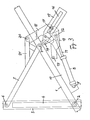
- numeral 1 denotes a door.wing which is pivotable around an intermediate horizontal pivot 2 located, for example, substantially at a distance from the bottom end of wing 1, which corresponds to one-third of the height of said wing 1.
- This horizontal pivot 2 around which the wing is pivotable is so guided as to be vertically slidable in guides.4 along fixed lateral uprights 3, that may be the jambs of the fixed doorframe.
- wing 1 a pivotable guiding arm 5 is provided between this wing and the respective upright 3, and is pivotally connected at 6 to the upper part of the respective upright 3, while at 7 it is pivotally connected to the door wing 1, for example at a point in which the distance from the top end of the door wing substantially corresponds to one-third of the height of said wing 1.
- both the wing 1 and the two lateral pivotable guiding arms 5 are set in a substantially vertical position, and are parallel to each other.
- the lateral pivotable guiding arms 5 are located in correspondence of the upper part of wing 1, i.e., over the point 7 of their pivotal connection to the said wing 1.
- both the wing 1 and the lateral pivotable guiding arms 5 are set in a substantially horizontal, parallel position in the upper part of the door opening.
- the lateral pivotable arms 5 are however situated on the opposite side to the point 7 'of their pivotal connection to the door wing 1, i.e., they perform a rotation over 180° relatively to the said wing, as they pass from the closed to the opened position, and vice-versa.
- a hydraulic or pneumatic cylinder 8 is provided on at least one side of the door wing 1, and is pivotally connected at 9 to a flange 10 which is integral with the said wing 1.
- the stem 11 of said cylinder 8 is pivotally connected at 12 to a lever arm 13 which is fulcrumed at 14 about the flange 10 being integral with the door wing 1.
- a pivotable actuating arm 15 is fulcrumed about the flange 10 and is rotated together with the lever arm 13, the two arms 13 and 15 being, for example, keyed onto the same pivot pin 14.
- a longitudinal slot 16 is provided, along which there is slidably guided the articulated joint 17 between two levers 18 that are pivotally connected, the one at 19 to the flange 10 which is integral with the door wing 1, and the other at 20 to an extension 21 of the respective lateral pivotable guiding arm 5.
- the stem 11 of cylinder 8 In the closed position of the door wing 1, the stem 11 of cylinder 8 is retracted, and the articulated joint 17 between the two levers 18 is situated in the guide slot 16 toward the free end of the pivotable actuating arm 15.
- the stem 11 of cylinder 8 To open the door, the stem 11 of cylinder 8 is pushed outwardly, thus causing the arm 13 and then also the actuating arm 15 to pivot about their fulcrum 14, and thus promoting through the scissors formed by the two levers 18, a relative angular movement of the wing 1 and the respective lateral pivotable guiding arm 5, so that this arm is angularly moved over 180° from its position at the side of the upper part of wing 1 to its position at the side of the median part of said wing 1, i.e., on the opposite side to the articulation 7.
- this wing is moved from its closed to its opened position, while the articulated joint 17 between the two levers 18 is moved along the longitudinal slot 16 in the actuating arm 15, away from the free end thereof.
- the door wing 1 is similarly moved from its opened to its closed position, when the stem 11 of cylinder 8 is retracted.
Landscapes
- Power-Operated Mechanisms For Wings (AREA)
- Engineering & Computer Science (AREA)
- Mechanical Engineering (AREA)
Applications Claiming Priority (2)
| Application Number | Priority Date | Filing Date | Title |
|---|---|---|---|
| IT1516585U IT8515165V0 (it) | 1985-05-02 | 1985-05-02 | Dispositivo d azionamento per porte con battente oscillante inorno ad un asse orizzontale intermedio |
| IT1516585U | 1985-05-02 |
Publications (2)
| Publication Number | Publication Date |
|---|---|
| EP0200139A2 true EP0200139A2 (de) | 1986-11-05 |
| EP0200139A3 EP0200139A3 (de) | 1987-04-15 |
Family
ID=11146901
Family Applications (1)
| Application Number | Title | Priority Date | Filing Date |
|---|---|---|---|
| EP86105503A Withdrawn EP0200139A3 (de) | 1985-05-02 | 1986-04-21 | Antriebsvorrichtung für ein, um eine horizontale Mittelachse schwingendes Tor |
Country Status (2)
| Country | Link |
|---|---|
| EP (1) | EP0200139A3 (de) |
| IT (1) | IT8515165V0 (de) |
Cited By (3)
| Publication number | Priority date | Publication date | Assignee | Title |
|---|---|---|---|---|
| DE4312955A1 (de) * | 1993-04-21 | 1994-10-27 | Goetz Entwicklung & Lizenz | Ausstelleinrichtung für kipp- und schwenkbare Fenster |
| AT411086B (de) * | 2002-01-18 | 2003-09-25 | Man Sonderfahrzeuge Ag | Lagerungs-, öffnungs- und schliessmechanismus für eine einen raum hinter ihr verschliessende klappe |
| US8567475B2 (en) | 2011-05-04 | 2013-10-29 | Kenneth Eugene Boone | Overhead gate systems |
Family Cites Families (2)
| Publication number | Priority date | Publication date | Assignee | Title |
|---|---|---|---|---|
| FR2379684A1 (fr) * | 1977-02-04 | 1978-09-01 | Faiveley Sa | Dispositif de manoeuvre d'un element d'obturation et application |
| GB8306372D0 (en) * | 1983-03-08 | 1983-04-13 | Manta Systems Remote Control L | Door operating mechanism |
-
1985
- 1985-05-02 IT IT1516585U patent/IT8515165V0/it unknown
-
1986
- 1986-04-21 EP EP86105503A patent/EP0200139A3/de not_active Withdrawn
Cited By (3)
| Publication number | Priority date | Publication date | Assignee | Title |
|---|---|---|---|---|
| DE4312955A1 (de) * | 1993-04-21 | 1994-10-27 | Goetz Entwicklung & Lizenz | Ausstelleinrichtung für kipp- und schwenkbare Fenster |
| AT411086B (de) * | 2002-01-18 | 2003-09-25 | Man Sonderfahrzeuge Ag | Lagerungs-, öffnungs- und schliessmechanismus für eine einen raum hinter ihr verschliessende klappe |
| US8567475B2 (en) | 2011-05-04 | 2013-10-29 | Kenneth Eugene Boone | Overhead gate systems |
Also Published As
| Publication number | Publication date |
|---|---|
| EP0200139A3 (de) | 1987-04-15 |
| IT8515165V0 (it) | 1985-05-02 |
Similar Documents
| Publication | Publication Date | Title |
|---|---|---|
| US5205073A (en) | Counterbalanced door assembly with reduced initial closing force | |
| US4617758A (en) | Self-locking window operator | |
| US4766820A (en) | Hopper car with automatic discharge door mechanism | |
| EP0492743A1 (de) | Schwenkschiebetür für Fahrzeuge | |
| CN107882461B (zh) | 一种能自动对照的防潮密闭门自动启闭装置 | |
| JPH0515571B2 (de) | ||
| EP0120853B1 (de) | Türverriegelungssystem | |
| GB1428141A (en) | Sliding door mechanism | |
| CA1268190A (en) | Mechanism for opening, closing and locking two leaved doors for cable cars | |
| HU191511B (en) | Double-acting door for vehicles | |
| US4454685A (en) | Vehicle door construction | |
| EP0200139A2 (de) | Antriebsvorrichtung für ein, um eine horizontale Mittelachse schwingendes Tor | |
| CN107849889A (zh) | 具有主驱动器和辅助驱动器的门驱动器 | |
| US2141298A (en) | Vehicle door construction | |
| US4206571A (en) | Bunker closure door operating mechanism | |
| CA1106860A (en) | Sliding plug door mechanisms | |
| CN212559041U (zh) | 门刀开闭结构 | |
| GB2044838A (en) | Improvements in or relating to sliding doors | |
| GB2059498A (en) | Elevating roof mechanism | |
| AT383854B (de) | Einrichtung zum oeffnen und schliessen eines tores | |
| JPH0511114Y2 (de) | ||
| FI91986B (fi) | Kääntölaite nostolamelliovien yhteydessä | |
| SU1020557A1 (ru) | Устройство дл открывани и закрывани створки | |
| SU1687754A1 (ru) | Устройство дл открывани и закрывани двери | |
| SU1444200A1 (ru) | Устройство дл открывани и закрывани створок крыши вагона |
Legal Events
| Date | Code | Title | Description |
|---|---|---|---|
| PUAI | Public reference made under article 153(3) epc to a published international application that has entered the european phase |
Free format text: ORIGINAL CODE: 0009012 |
|
| AK | Designated contracting states |
Kind code of ref document: A2 Designated state(s): AT BE CH DE FR GB IT LI LU NL SE |
|
| RBV | Designated contracting states (corrected) |
Designated state(s): AT BE CH DE FR GB IT LI NL SE |
|
| PUAL | Search report despatched |
Free format text: ORIGINAL CODE: 0009013 |
|
| AK | Designated contracting states |
Kind code of ref document: A3 Designated state(s): AT BE CH DE FR GB IT LI NL SE |
|
| STAA | Information on the status of an ep patent application or granted ep patent |
Free format text: STATUS: THE APPLICATION IS DEEMED TO BE WITHDRAWN |
|
| 18D | Application deemed to be withdrawn |
Effective date: 19871016 |