EP0199466B1 - Dispensing method for improved uniformity in dispensing - Google Patents
Dispensing method for improved uniformity in dispensing Download PDFInfo
- Publication number
- EP0199466B1 EP0199466B1 EP86302223A EP86302223A EP0199466B1 EP 0199466 B1 EP0199466 B1 EP 0199466B1 EP 86302223 A EP86302223 A EP 86302223A EP 86302223 A EP86302223 A EP 86302223A EP 0199466 B1 EP0199466 B1 EP 0199466B1
- Authority
- EP
- European Patent Office
- Prior art keywords
- pressure
- container
- dispensing
- liquid
- probe
- Prior art date
- Legal status (The legal status is an assumption and is not a legal conclusion. Google has not performed a legal analysis and makes no representation as to the accuracy of the status listed.)
- Expired - Lifetime
Links
- 238000000034 method Methods 0.000 title claims description 18
- 239000007788 liquid Substances 0.000 claims description 55
- 239000000523 sample Substances 0.000 claims description 29
- 230000008859 change Effects 0.000 claims description 5
- 230000003213 activating effect Effects 0.000 claims description 3
- 238000012360 testing method Methods 0.000 description 21
- 230000005499 meniscus Effects 0.000 description 9
- 230000007423 decrease Effects 0.000 description 6
- 238000012544 monitoring process Methods 0.000 description 6
- 238000013459 approach Methods 0.000 description 4
- 238000001514 detection method Methods 0.000 description 3
- 238000001704 evaporation Methods 0.000 description 3
- 230000008020 evaporation Effects 0.000 description 3
- 230000004044 response Effects 0.000 description 3
- 238000013022 venting Methods 0.000 description 3
- 230000000694 effects Effects 0.000 description 2
- 230000008030 elimination Effects 0.000 description 2
- 238000003379 elimination reaction Methods 0.000 description 2
- 230000002028 premature Effects 0.000 description 2
- 238000012163 sequencing technique Methods 0.000 description 2
- 230000001133 acceleration Effects 0.000 description 1
- 238000004458 analytical method Methods 0.000 description 1
- 238000003556 assay Methods 0.000 description 1
- 230000008901 benefit Effects 0.000 description 1
- 239000003153 chemical reaction reagent Substances 0.000 description 1
- 238000007796 conventional method Methods 0.000 description 1
- 238000001816 cooling Methods 0.000 description 1
- 230000003247 decreasing effect Effects 0.000 description 1
- 230000006870 function Effects 0.000 description 1
- 230000000977 initiatory effect Effects 0.000 description 1
- 239000007791 liquid phase Substances 0.000 description 1
- 230000010355 oscillation Effects 0.000 description 1
- 239000013610 patient sample Substances 0.000 description 1
- 230000035515 penetration Effects 0.000 description 1
- 230000008569 process Effects 0.000 description 1
- 238000012545 processing Methods 0.000 description 1
- 230000000630 rising effect Effects 0.000 description 1
- 230000003068 static effect Effects 0.000 description 1
- 238000012546 transfer Methods 0.000 description 1
- 230000001052 transient effect Effects 0.000 description 1
Images
Classifications
-
- G—PHYSICS
- G01—MEASURING; TESTING
- G01N—INVESTIGATING OR ANALYSING MATERIALS BY DETERMINING THEIR CHEMICAL OR PHYSICAL PROPERTIES
- G01N35/00—Automatic analysis not limited to methods or materials provided for in any single one of groups G01N1/00 - G01N33/00; Handling materials therefor
- G01N35/10—Devices for transferring samples or any liquids to, in, or from, the analysis apparatus, e.g. suction devices, injection devices
- G01N35/1009—Characterised by arrangements for controlling the aspiration or dispense of liquids
- G01N35/1016—Control of the volume dispensed or introduced
-
- G—PHYSICS
- G01—MEASURING; TESTING
- G01N—INVESTIGATING OR ANALYSING MATERIALS BY DETERMINING THEIR CHEMICAL OR PHYSICAL PROPERTIES
- G01N35/00—Automatic analysis not limited to methods or materials provided for in any single one of groups G01N1/00 - G01N33/00; Handling materials therefor
- G01N35/00029—Automatic analysis not limited to methods or materials provided for in any single one of groups G01N1/00 - G01N33/00; Handling materials therefor provided with flat sample substrates, e.g. slides
-
- G—PHYSICS
- G01—MEASURING; TESTING
- G01N—INVESTIGATING OR ANALYSING MATERIALS BY DETERMINING THEIR CHEMICAL OR PHYSICAL PROPERTIES
- G01N35/00—Automatic analysis not limited to methods or materials provided for in any single one of groups G01N1/00 - G01N33/00; Handling materials therefor
- G01N35/10—Devices for transferring samples or any liquids to, in, or from, the analysis apparatus, e.g. suction devices, injection devices
- G01N35/1009—Characterised by arrangements for controlling the aspiration or dispense of liquids
- G01N2035/1025—Fluid level sensing
-
- G—PHYSICS
- G01—MEASURING; TESTING
- G01N—INVESTIGATING OR ANALYSING MATERIALS BY DETERMINING THEIR CHEMICAL OR PHYSICAL PROPERTIES
- G01N35/00—Automatic analysis not limited to methods or materials provided for in any single one of groups G01N1/00 - G01N33/00; Handling materials therefor
- G01N35/10—Devices for transferring samples or any liquids to, in, or from, the analysis apparatus, e.g. suction devices, injection devices
- G01N35/1081—Devices for transferring samples or any liquids to, in, or from, the analysis apparatus, e.g. suction devices, injection devices characterised by the means for relatively moving the transfer device and the containers in an horizontal plane
- G01N35/1083—Devices for transferring samples or any liquids to, in, or from, the analysis apparatus, e.g. suction devices, injection devices characterised by the means for relatively moving the transfer device and the containers in an horizontal plane with one horizontal degree of freedom
-
- G—PHYSICS
- G01—MEASURING; TESTING
- G01N—INVESTIGATING OR ANALYSING MATERIALS BY DETERMINING THEIR CHEMICAL OR PHYSICAL PROPERTIES
- G01N35/00—Automatic analysis not limited to methods or materials provided for in any single one of groups G01N1/00 - G01N33/00; Handling materials therefor
- G01N35/10—Devices for transferring samples or any liquids to, in, or from, the analysis apparatus, e.g. suction devices, injection devices
- G01N35/1095—Devices for transferring samples or any liquids to, in, or from, the analysis apparatus, e.g. suction devices, injection devices for supplying the samples to flow-through analysers
-
- Y—GENERAL TAGGING OF NEW TECHNOLOGICAL DEVELOPMENTS; GENERAL TAGGING OF CROSS-SECTIONAL TECHNOLOGIES SPANNING OVER SEVERAL SECTIONS OF THE IPC; TECHNICAL SUBJECTS COVERED BY FORMER USPC CROSS-REFERENCE ART COLLECTIONS [XRACs] AND DIGESTS
- Y10—TECHNICAL SUBJECTS COVERED BY FORMER USPC
- Y10T—TECHNICAL SUBJECTS COVERED BY FORMER US CLASSIFICATION
- Y10T436/00—Chemistry: analytical and immunological testing
- Y10T436/25—Chemistry: analytical and immunological testing including sample preparation
- Y10T436/2575—Volumetric liquid transfer
Definitions
- a negative pressure is preferably drawn onto the liquid to pull meniscus M, shown first as a solid line, back to dotted line 124 but preferably not to dotted line 128.
- this serves to prevent the deceleration from prematurely ejecting small amounts of liquid onto a test element.
- Fig. 5B a slight increase in pressure is provided, arrow 130, to cause a convex meniscus M'.
- Fig. 5C by the actual dispensing of the liquid caused by a large increase in pump pressure.
- a negative pressure change can occur that will be monitored by the pressure transducer as a ⁇ V in excess of -V T oi, that necessitates an increase in pressure provided by a one-half step advance by motor 64. For example, in some cases cooling can cause a pressure decrease.
Landscapes
- Physics & Mathematics (AREA)
- Health & Medical Sciences (AREA)
- Life Sciences & Earth Sciences (AREA)
- Chemical & Material Sciences (AREA)
- Analytical Chemistry (AREA)
- Biochemistry (AREA)
- General Health & Medical Sciences (AREA)
- General Physics & Mathematics (AREA)
- Immunology (AREA)
- Pathology (AREA)
- Automatic Analysis And Handling Materials Therefor (AREA)
- Auxiliary Methods And Devices For Loading And Unloading (AREA)
Description
- This invention relates to a method for aspirating liquid into a container, and for dispensing such aspirated liquid. More specifically, it relates to a method for controlling the pressure within- such container to achieve greater uniformity in dispensing.
- Liquid dispensers have been used in analyzers for the detection of the concentration of liquid ana- lytes using as analysis means, test elements that contain within themselves the necessary reagents to permit such detection. Examples of such analyzers are described in U.S. Patent Nos. 4,287,155, issued September 1, 1981, and 4,340,390, issued July 20, 1982. Examples of such test elements appear in U.S. Patent Nos. 3,992,158, issued November 16, 1976; 4,053,381, issued October 11, 1977; and 4,258,001, issued March 24, 1981. The conventional method for dispensing liquid onto such test elements using such analyzers has been to aspirate test liquid from a relatively large container, into a dispensing container. The dispensing container is then moved to a position immediately above such a test element, and a fraction (e.g., 10 I.d) of the aspirated liquid is dispensed. The dispensing container is fluidly connected, in such analyzers, to a pressurizing means. Such means generates both the operative partial vacuum needed to aspirate an amount of liquid into the container, and the partial pressure operative to dispense that aspirated liquid, in fractional amounts, onto a plurality of test elements. A pressure transducer is also conventionally included to ascertain the pressure within the container, so as to detect the occurrence of the desired dispensing event versus a failure to dispense. A microprocessor generally is used to control the apparatus in response to the conditions sensed.
- Document EP-A 0 169 071 (Priority date: 19.07.84; Publication date 22.01.86; prior art pursuant to Article 54(3) EPC) describes a liquid dispenser and a method for detecting the penetration of a liquid meniscus by the dispenser, the dispenser being subsequently used for aspirating and dispersing the liquid. The method described enables the level of liquid in a container to be accurately determined.
- Because only a fraction of the liquid is dispensed each time, one prior approach to dispensing liquid onto a test element has been to vent the dispensing container after each dispensing event. Such an approach is described in U.S. Patent No. 4.041.995, issued by R. L. Columbus on August 16,1977, and in U.S. Patent No. 4.452.899 (col. 4, lines 34-40) issued by Wilton Alston on June 5, 1984. Although this approach generally has worked satisfactorily, on occasion the volume of liquid so dispensed has deviated from that desired. This occurs as follows:
- As is described in the aforesaid '899 patent, movement of the dispensing probe into position directly above a test element can cause prespotting of the test element when the probe decelerates to a stop, unless the process includes a partial withdrawal of the meniscus in the dispensing aperture. Such partial withdrawal is achieved by backing up the dispensing pump of the pressurizing means enough to create a slight partial vacuum. This in turn requires any vent that is present to be closed, and remain closed during the actual dispensing step. While the vent is closed, evaporation of the liquid can occur, causing an increase in pressure to build in the air above the liquid in the dispensing container. Such build-up of pressure adds to the pressure delivered during dispensing, so as to cause a larger volume to be dispensed than would be the case if no build-up had occurred, e.g., if venting had occurred immediately before dispensing. The build-up of pressure can also occur when venting cannot be used. An example of this is those instances when a relatively large volume of liquid (e.g., 110-230 111) is present in the dispensing container. In that case, the vent is kept closed between dispensing events, because the weight of the large volume would cause the liquid to run out of the container if the vent were open. In other words, at large liquid volumes it has been the practice to operate such dispensing apparatus as though no vent were present. Because the vent is closed, a build-up of pressure tends to occur.
- Regardless of the reason for the build-up in air pressure, it is relatively unpredictable. Thus it cannot be compensated for by factory calibration. As a result, significant deviations from the desired volume can occur in an unpredictable fashion, for example, as much as 10%.
- Thus, the problem to be solved by this invention is to provide such a dispensing method that achieves greater uniformity in the amount of liquid that is dispensed.
- In accordance with the present invention, there is provided a method for dispensing liquid using a probe for mounting a container having a dispensing aperture; and pressurizing means fluidly connected to said probe for generating an operative positive or negative pressure differential relative to atmospheric pressure, within a mounted container; the method comprising the steps of
- a) repeatedly sensing and repeatedly generating as a corresponding electrical signal, the air pressure above the level of the liquid within such container;
- b) reading and storing the signal at at least one time when it represents a desired baseline air pressure;
- c) determining the difference between the stored signal and the signal repeatedly sensed in step a) as a difference value; and
- d) activating said pressurizing means to produce a negative or positive pressure differential when the determining step c) detects that the absolute value of said difference value is greater than the value of a stored tolerance factor.
- Thus, it is an advantageous effect of the invention that the amount of liquid dispensed by the apparatus is more accurately controlled within the desired limits.
- It is a further advantageous effect of the invention that the need for a venting means has been eliminated.
- The present invention will now be described by way of example with reference to the attached drawings, in which:
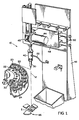
- Fig. 1 is a fragmentary perspective view of a dispensing apparatus with which the invention can be practiced;
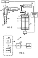
- Fig. 2 is a fragmentary, partially schematic view illustrating certain details of the dispensing apparatus, wherein parts and positions are not shown to scale;
- Fig. 3 is a schematic illustration of a microprocessor useful as a control means;
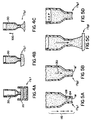
- Figs. 4A through 4C are fragmentary sectional views illustrating the stages of aspiration through which the dispensing container is processed relative to the supply of patient sample;
- Figs. 5A through 5D are fragmentary sectional views similar to Figs. 4A-4C, except illustrating the stages through which the dispensing container is processed after aspiration, including dispensing;
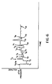
- Fig. 6 is an example of a voltage versus time signal trace generated by a transducer when carrying out the steps of the invention, the time units being arbitrary; and
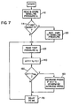
- Fig. 7 is a flow chart for programming the control means of the described apparatus to carry out the invention.
- The invention is particularly useful in colorimetric and potentiometric assays using analyzers and dried test elements of the type described in the above-noted patents. In addition, the invention is useful in any dispensing apparatus or method which aspirates liquid after moving the dispensing container from the atmosphere into a liquid phase, regardless of the steps that follow the dispensing of the aspirated liquid, and regardless whether the dispensing is onto a test element.
- Terms such as "up", "down", "lower", "vertical", "horizontal", and "bottom", as used herein refer to the orientation of parts when the apparatus is positioned in its customary position of use.
- A portion of a preferred
dispensing apparatus 10 is illustrated in Figs. 1 and 2. A plurality of relativelylarge sample containers 20 is provided in atray 22, which also supports removable, preferablydisposable dispensing containers 30. The purpose of the apparatus is to transfer liquid fromcontainer 20 tocontainer 30, and then dispense fromcontainer 30. Thecontainers 30 have, Fig. 2, alarger aperture 32 at one end to mate with aprobe 40, and asmaller aperture 34 at the opposite end for aspirating and dispensing. Each ofcontainers 20 is preferably provided with a pierceable closure orcap 24, Fig. 1. Theprobe 40 mounts thecontainers 30. Preferablyprobe 40 is mounted for vertical and horizontal movement on aframe 42, such movement being provided respectively by amotor 44 andgear 45, and by acar 48 carrying theprobe 40 horizontally onrails 50. Motor 44 can be a stepper motor or a D.C. motor with feedback control. - The combined movement of the car and probe is effective to carry the probe within the plane noted as "H", Fig. 1. Test elements E are held by
members 96 so as to intersect plane H, to permit dispensing of the liquid fromcontainer 30 onto the test element. - The movement of
probe 40 relative tocontainers 20 and test elements E is, of course, optional and of no direct consequence, except as hereinafter noted, to the control of pressures withincontainers 30 provided by this invention. Thus, an equally useful alternative arrangement would be one in whichprobe 40 is stationary, andcontainers 20 and elements E are moved into place relative to probe 40. - A
pressure line 52 provides a partial vacuum or a partial pressure, relative to atmospheric, to a dispensingcontainer 30 picked up by the probe. The pressure or vacuum is provided by means such as apiston 60 andpiston chamber 62, Fig. 2, driven by appropriate motor means 64. For example, movement ofpiston 60 from position "A" down to position "X" creates the operative partial vacuum that aspirates the liquid fromcontainer 20 intocontainer 30 at the appropriate time. Apressure transducer 70 is used to sense the pressure incontainer 30, for example to determine when proper dispensing of the liquid out ofcontainer 30 occurs. - Alternatively,
piston chamber 62 and its piston can be part ofprobe 40 so as to move up and down with the probe. - Appropriate control means 80 are provided to coordinate the actuation of
motor 44 andmotor 64, in response to conditions sensed by e.g.,transducer 70. Control means 80 can comprise a microprocessor or hard-wired logic circuits. Most preferably, it includes amicroprocessor 82, Fig. 3, particularly in light of the programming discussed hereinafter. As is conventional, such a microprocessor comprises acentral processing unit 84, for example, an Intel 8085 chip, andmemory unit 86 comprising one or more RAM's 88 and optionally one or more E PROM's 90. The microprocessor preferably is also wired to standard input/output devices, as shown, if the dispensing apparatus is part of a complete analyzer. - What is described above comprises a conventional dispensing apparatus. Such apparatus is also controlled conventionally via
microprocessor 82 to provide the following conventional aspirating and dispensing events (Figs. 4-6): To aspirate liquid intocontainer 30, Figs. 4A-4C, such container is first moved downwardly into the liquid supplied by acontainer 20, Fig. 4A. When negative pressure is supplied viaprobe 40 tocontainer 30 at a time Ti, such differential pressure will cause the liquid to rise intocontainer 30, Fig. 4B, which is completed by time T2. Thereafter,container 30 is withdrawn from the supply of liquid,arrow 100, Fig. 4C, and moved towards the station at which liquid is to be dispensed, Fig. 5A, preferably onto test element E. When the probe begins to decelerate, as suggested byarrows 110 of decreasing length, a negative pressure is preferably drawn onto the liquid to pull meniscus M, shown first as a solid line, back to dottedline 124 but preferably not to dottedline 128. As explained in the aforesaid U.S. Patent No. 4,452,899, this serves to prevent the deceleration from prematurely ejecting small amounts of liquid onto a test element. Thereafter, Fig. 5B, a slight increase in pressure is provided,arrow 130, to cause a convex meniscus M'. This is followed, Fig. 5C, by the actual dispensing of the liquid caused by a large increase in pump pressure. - Because this much of the control of aspiration and dispensing is conventional, further explanation of the logic used to
program microprocessor 82 to achieve this is unnecessary. - The pressure changes discussed above that occur in the air volume in
container 30 above the liquid are shown in the pressure trace of Fig. 6, wherein pressures are represented by the voltage output oftransducer 70 against time. At time Ti,piston 60 is withdrawn towards position X, Fig. 2, to initiate conditions that will lead to aspiration. This corresponds to the container condition shown in Fig. 4A. As flow begins intocontainer 30, time T2 the trace reverses its negative direction until aspiration is completed, Fig. 4B. Preferably, to eject a small fraction of aspirated liquid back intocontainer 20 and thus to force the upper meniscus into a concave shape, a small positive pressure is applied bypiston 60, creating a positive preliminary spike shown at T3, Fig. 6. Otherwise, additional stored energy in a convex meniscus adds unacceptably to dispensed quantity volume. Thereafter,container 20 is withdrawn from the external liquid, Fig. 4C, at a time T4, creating a dithering variation in the trace of Fig. 6. At time Tg,motor 64 is activated to withdrawpiston 60, to create a sharply concave meniscus as shown asline 124, Fig. 5A, preparatory to deceleration byprobe 40 as it approaches the test element. At time Tio, after the container has completed its motion,motor 64 is reversed to create a slight increase in pressure, pushing the concave meniscus out to a convex position M', Fig. 5B. Thereafter, a large spike of positive pressure is delivered bymotor 64 andpiston 60, time T13, Figs. 5C and 6, to force the desired quantity of liquid to dispense. - In accord with one aspect of the invention the apparatus described above is used to provide a more accurate volume of dispensed liquid as follows:
Piston 60 is controlled in response totransducer 70 and through the use ofmicroprocessor 82, to override any build-up or lessening of pressure such as would otherwise unacceptably alter the dispensed volume. It has been found that this is done most preferably in conjunction with the elimination of the vent means conventionally interposed in pressure line 52 (Fig. 2). The elimination of the vent means has the advantage that such vent means is usually the first component in the described pressure system to develop leaks. - At various stages there is a time, Fig. 5D, before the next dispensing event when pressure AP can be built up, as by evaporation. This pressure change is compensated for, first, by detecting a change in excess of an acceptable threshold defined herein as tolerance factor, and second by incrementally advancing or withdrawing piston 60 a predetermined distance by incrementally advancing or withdrawing motor 64 a predetermined number of half-steps, for example, one.
- Referring again to the pressure curve represented by the voltage output in Fig. 6, of the transducer, a baseline pressure is read at various appropriate times. The purpose for reading this pressure is to establish a baseline against which subsequent pressures are subtracted, and the difference compared to a tolerance factor, stored as a value VTol. VTol is selected to be large enough to accommodate trivial and temporary variations, but small enough to allow detection of harmful variations that exceed acceptable limits. VTol is either preset at the factory, or provided as a calibration value.
- The baseline pressure is reread and restored as an updated value on different occasions, because the desired baseline pressure changes as the conditions change. The first of these times is at T4, after the ejection of some of the aspirated liquid has occurred at time T3. The baseline pressure is read as a voltage, labeled Vp. At this point, an offset pressure value, Voff, discussed in detail hereafter, is added and the sum stored in memory, since no dispensing has occurred yet from this particular container. In addition, the microprocessor memory includes the stored tolerance factor, as a ± VTol, for example, ± 40 mV. Thus, after
container 30 has been withdrawn from the source of liquid (time T4 to Ts) the sum of (Vp + Voff) is stored for later use, that is, when the pressure monitoring algorithm hereinafter described, is enabled. The microprocessor enables thetransducer 70 to monitor the pressure conditions in dispensingcontainer 30 above the liquid commencing with time Ts, Fig. 6. The first result is to force the pump motor to raise the pressure to a value of Vp + Voff by time Te. Preferably, the monitoring algorithm is then disabled while the probe accelerates to a constant velocity, time T7. As evaporation takes place, time T7 to time Ts, Figs. 5D and 6, a ΔP increase in pressure takes place. This continues until the transducer detects that the increased pressure exceeds Vi plus the tolerance factor VTol. (At times T7 to Tg, Vi = Vp + Voff.) At such a time T7 and T8, Fig. 6,motor 64 is activated to, in this case, withdraw piston 60 a predetermined amount, for example, an amount corresponding to one-half a step of the motor (such as position B or C in Fig. 2). As a result, the internal air pressure is returned to the baseline value Vi. - As noted above, at various times in the cycle of operation,
probe 40 accelerates, and under the preferred method of operation, the pressure monitoring algorithm is disabled at such times. Another such algorithm-disabling time is time Tg, which allows a negative pressure to be drawn on the liquid bypump 64. As described for Fig. 5A, this allows the probe andcontainer 30 to decelerate without causing premature ejection of liquid. - Thereafter, the pressure monitor algorithm is re-enabled at time T10, and a new baseline pressure V1 is read and stored. Such new reading is necessitated by the fact that the expected baseline pressure plus Voff may be higher than Vp + Voff at time Te, due to a slight rising of the liquid meniscus in
aperture 34 of the container. If the old sum of Vp + Voff were to continue to be used, excessive dispensed volume would occur at time T13, if not premature dispensing. - Starting with time Tio, and in the manner described above,
transducer 70 initiates a half-step retreat of the motor at various times between Tio, and T13 when the test pressure detected exceeds the allowed value of Vi plus VTol. - At time T13, dispensing commences as noted above for Fig. 5C. During this part of the cycle, the pressure monitoring algorithm is disabled, and then re-enabled at time T14. At this time, yet another baseline pressure is read and stored, namely V2. The reason is that the value of the internal air pressure decreases after each quantity is dispensed. The amount of decrease equals, of course, the decrease in static head of pressure due to the remaining height of liquid to be dispensed. Thereafter, the pressure is monitored and corrected during time T14 to T18, as before, until the next dispensing event or until the probe accelerates.
- As a result of the corrective steps taken at, e.g., time T8 and between times T10 and T13 or T14 and T18, a more constant pressure is maintained in the atmosphere above the liquid of
container 30, and a more uniform volume is dispensed during each subsequent dispense cycle. - It will also be appreciated that a negative pressure change can occur that will be monitored by the pressure transducer as a ΔV in excess of -VToi, that necessitates an increase in pressure provided by a one-half step advance by
motor 64. For example, in some cases cooling can cause a pressure decrease. - A flow chart useful in
programming microprocessor 82 for the monitoring algorithm, using conventional programming techniques, appears in Fig. 7. The monitoring algorithm is a subroutine that is activated by the rest of the program of the microprocessor to function only whileprobe 40 is undergoing no acceleration or deceleration. Such a condition occurs at predetermined points in the sequencing of the analyzer, so that interrupts at predetermined points in the sequencing can be used to enable and disable this subroutine. As will be readily apparent, the algorithm routine is disabled, Fig. 6, e.g., during times T6-T7, and times T9 and Tio. - The
first algorithm step 112, Fig. 7, is to read and store in memory of the microprocessor a baseline pressure, which is generated as a voltage Vi produced bypressure transducer 70, for i = P, 1, 2, etc. Thus, the first such baseline pressure for a givencontainer 30 is Vp as noted above, then V1, V2, etc. Next, the microprocessor interrogates,step 114, as to whether the next drop to be dispensed is the first drop to be dispensed from a givencontainer 30. If and only if a microprocessor flag indicates that it is, then step 120 is carried out to add a suitable offset value, Voff such as 100 mv, to the baseline pressure reading Vp. Because of the nature of the problem being corrected, Voff is larger than VToi. As noted, this causesmotor 64 to advance to increase the pressure withinprobe 40. This increase in pressure just for the first drop metering has been found to give better metering results for that first drop. - Thereafter, the algorithm continues by reading the test pressure,
step 125, as evidenced by the voltage VT oftransducer 70. This value is then used to create a pressure difference ΔV, which is calculated,step 140, as the absolute value of VT-Vi. Next,step 150, the microprocessor queries as to whether ΔV so defined is greater than the tolerance factor VTol permanently left in memory. (VTol may be stored in the same, or different, memory means as V;.). If yes, the microprocessor further calculates,step 160, whether VT > V; or not. If the former, the microprocessor sends out a signal tomotor 64 to withdraw piston 60 a small amount, such as by one-half a step, to decrease the pressure incontainer 30. If the latter condition is determined (Vi > VT), thenmicroprocessor 82 sends a signal tomotor 64 to advance that small amount, e.g., 1/2 a step, to increase pressure withincontainer 30. - In the meantime,
step 170 is executed which runs a delay clock for a suitable time, such as 25 milliseconds, before looping back to step 125 to repeat the sequence. The 25 ms delay is used to allow transient oscillations in pressure to die out before making another test reading. - It will be appreciated that an alternative procedure to that just described, which is the mathematical equivalent, is to a) determine whether VT, evidencing the test pressure, is larger or smaller than Vi, b) if VT is larger, then determine whether VT exceeds the value of V; + VTol; otherwise determine whether VT is less than V; - VTol, and c) if step b) determines that VT exceeds (Vi + VTol) or is less than (Vi - VTol), then initiating a small pressure decrease or increase, respectively, by activating the pump motor a small amount and in the proper direction.
Claims (4)
Applications Claiming Priority (2)
| Application Number | Priority Date | Filing Date | Title |
|---|---|---|---|
| US718319 | 1985-04-01 | ||
| US06/718,319 US4675301A (en) | 1985-04-01 | 1985-04-01 | Method for correcting for changes in air pressure above a liquid to be dispensed from a container mounted on a probe |
Publications (3)
| Publication Number | Publication Date |
|---|---|
| EP0199466A2 EP0199466A2 (en) | 1986-10-29 |
| EP0199466A3 EP0199466A3 (en) | 1987-08-19 |
| EP0199466B1 true EP0199466B1 (en) | 1990-08-22 |
Family
ID=24885665
Family Applications (1)
| Application Number | Title | Priority Date | Filing Date |
|---|---|---|---|
| EP86302223A Expired - Lifetime EP0199466B1 (en) | 1985-04-01 | 1986-03-26 | Dispensing method for improved uniformity in dispensing |
Country Status (5)
| Country | Link |
|---|---|
| US (1) | US4675301A (en) |
| EP (1) | EP0199466B1 (en) |
| JP (1) | JPS61231463A (en) |
| CA (1) | CA1297458C (en) |
| DE (1) | DE3673549D1 (en) |
Cited By (2)
| Publication number | Priority date | Publication date | Assignee | Title |
|---|---|---|---|---|
| US5915282A (en) | 1995-12-14 | 1999-06-22 | Abbott Laboratories | Fluid handler and method of handling a fluid |
| US5965828A (en) * | 1995-12-14 | 1999-10-12 | Abbott Laboratories | Fluid handler and method of handling a fluid |
Families Citing this family (53)
| Publication number | Priority date | Publication date | Assignee | Title |
|---|---|---|---|---|
| DE3614955C1 (en) * | 1986-05-02 | 1987-08-06 | Schulz Peter | Sample distribution system |
| JPS62299769A (en) * | 1986-06-20 | 1987-12-26 | Fuji Photo Film Co Ltd | Dispenser |
| JPS6375565A (en) * | 1986-09-18 | 1988-04-05 | Toshiba Corp | Sampling monitor |
| JPS63177530A (en) * | 1987-01-19 | 1988-07-21 | Toshiba Corp | Method and device for die bonding |
| JPH076998B2 (en) * | 1987-12-04 | 1995-01-30 | 富士写真フイルム株式会社 | Automatic dispenser and spotting method |
| WO1989010193A1 (en) * | 1988-04-29 | 1989-11-02 | Cavro Scientific Instruments, Inc. | Improved method and apparatus for pipetting liquids |
| US4967606A (en) * | 1988-04-29 | 1990-11-06 | Caveo Scientific Instruments, Inc. | Method and apparatus for pipetting liquids |
| US5204269A (en) * | 1989-03-13 | 1993-04-20 | Beckman Instruments, Inc. | Sample handling for chemistry analyzers |
| US5250262A (en) | 1989-11-22 | 1993-10-05 | Vettest S.A. | Chemical analyzer |
| US5089229A (en) | 1989-11-22 | 1992-02-18 | Vettest S.A. | Chemical analyzer |
| JPH081471Y2 (en) * | 1990-09-06 | 1996-01-17 | プレシジョン・システム・サイエンス株式会社 | Dispensing device |
| US5111703A (en) * | 1990-09-10 | 1992-05-12 | Eastman Kodak Company | Liquid aspirating pipette and dispensing system |
| US5409841A (en) * | 1991-03-14 | 1995-04-25 | Chow; Timothy | Ultraviolet light sterilized sampling device and method of sampling |
| US5143849A (en) * | 1991-03-21 | 1992-09-01 | Eastman Kodak Company | Tip to surface spacing for optimum dispensing controlled by a detected pressure change in the tip |
| US5133392A (en) * | 1991-04-10 | 1992-07-28 | Eastman Kodak Company | Liquid injection using container bottom sensing |
| JP2539126Y2 (en) * | 1991-08-26 | 1997-06-25 | 東亜医用電子株式会社 | Sample suction monitoring device with automatic adjustment function |
| JP2515938B2 (en) * | 1991-10-18 | 1996-07-10 | アロカ株式会社 | Liquid suction method |
| US5677195A (en) * | 1991-11-22 | 1997-10-14 | Affymax Technologies N.V. | Combinatorial strategies for polymer synthesis |
| US6849462B1 (en) | 1991-11-22 | 2005-02-01 | Affymetrix, Inc. | Combinatorial strategies for polymer synthesis |
| US6943034B1 (en) | 1991-11-22 | 2005-09-13 | Affymetrix, Inc. | Combinatorial strategies for polymer synthesis |
| DE4209620C1 (en) * | 1992-03-25 | 1993-12-16 | Eppendorf Geraetebau Netheler | Method for correcting the volume error ïV in a pipetting system |
| FI96666C (en) * | 1992-05-04 | 1996-08-12 | Wallac Oy | Procedure and air piston pipette for dosing liquid |
| CA2136630A1 (en) * | 1992-06-08 | 1993-12-23 | John E. Waylet, Jr. | Liquid dispensing system |
| JP3386505B2 (en) * | 1993-03-02 | 2003-03-17 | 株式会社東芝 | Automatic analyzer |
| US5368196A (en) * | 1993-03-25 | 1994-11-29 | Fluid Management Limited Partnership | Apparatus for metering and dispensing flowable materials to form a blended composition |
| US5540081A (en) * | 1993-08-31 | 1996-07-30 | Abbott Laboratories | Pipetting apparatus with clot detection |
| JP3420824B2 (en) * | 1994-04-15 | 2003-06-30 | 富士写真フイルム株式会社 | Method and apparatus for spotting sample liquid on dry analytical film piece |
| US5503036A (en) * | 1994-05-09 | 1996-04-02 | Ciba Corning Diagnostics Corp. | Obstruction detection circuit for sample probe |
| US7323298B1 (en) | 1994-06-17 | 2008-01-29 | The Board Of Trustees Of The Leland Stanford Junior University | Microarray for determining the relative abundances of polynuceotide sequences |
| US7625697B2 (en) | 1994-06-17 | 2009-12-01 | The Board Of Trustees Of The Leland Stanford Junior University | Methods for constructing subarrays and subarrays made thereby |
| CA2175001A1 (en) * | 1995-05-01 | 1996-11-02 | Andrew Shelley Foote | Method of avoiding decreased-size first drops when aspirating from immersed rest conditions |
| US5811306A (en) * | 1995-09-04 | 1998-09-22 | Fuji Photo Film Co., Ltd. | Liquid spotting method |
| US5723795A (en) * | 1995-12-14 | 1998-03-03 | Abbott Laboratories | Fluid handler and method of handling a fluid |
| JP2804951B2 (en) * | 1996-02-23 | 1998-09-30 | 九州日本電気株式会社 | Precise quantitative discharge method and discharge device |
| US5853665A (en) * | 1997-09-16 | 1998-12-29 | Coulter International Corp. | Apparatus and method for monitoring vent line vacuum |
| SE9803048D0 (en) | 1998-09-09 | 1998-09-09 | Siemens Elema Ab | Dispenser unit for non-gaseous flowable material |
| US6446878B1 (en) * | 1999-03-01 | 2002-09-10 | Sanjeev Chandra | Apparatus and method for generating droplets |
| US6370942B1 (en) | 2000-05-15 | 2002-04-16 | Dade Behring Inc. | Method for verifying the integrity of a fluid transfer |
| JP3903015B2 (en) * | 2003-02-05 | 2007-04-11 | 株式会社日立ハイテクノロジーズ | Chemical analyzer |
| US7273591B2 (en) * | 2003-08-12 | 2007-09-25 | Idexx Laboratories, Inc. | Slide cartridge and reagent test slides for use with a chemical analyzer, and chemical analyzer for same |
| WO2005036294A1 (en) * | 2003-10-06 | 2005-04-21 | Nordson Corporation | Compensating pressure controller for fluid dispenser and method |
| US7396512B2 (en) | 2003-11-04 | 2008-07-08 | Drummond Scientific Company | Automatic precision non-contact open-loop fluid dispensing |
| US7588733B2 (en) | 2003-12-04 | 2009-09-15 | Idexx Laboratories, Inc. | Retaining clip for reagent test slides |
| US7479391B2 (en) * | 2004-12-10 | 2009-01-20 | Tecan Trading Ag | Pipetting apparatus with integrated liquid level and/or gas bubble detection |
| EP1745851B1 (en) | 2005-07-22 | 2015-02-25 | Tecan Trading AG | Process, device and computerprogramm product for the classification of a liquid |
| DE202006010293U1 (en) * | 2005-07-22 | 2006-08-31 | Tecan Trading Ag | Pipetting device with computer program product for accepting or discarding pipetted liquid samples |
| US9116129B2 (en) * | 2007-05-08 | 2015-08-25 | Idexx Laboratories, Inc. | Chemical analyzer |
| JP2013076674A (en) * | 2011-09-30 | 2013-04-25 | Fujifilm Corp | Dispenser and suction nozzle position controlling method |
| DE102012209314B4 (en) | 2012-06-01 | 2015-04-02 | Albert-Ludwigs-Universität Freiburg | Device and method for dispensing or receiving a liquid volume |
| GB201212155D0 (en) | 2012-07-09 | 2012-08-22 | Stratec Biomedical Ag | A device and method for uptake or release of a liquid |
| US9797916B2 (en) | 2014-01-10 | 2017-10-24 | Idexx Laboratories, Inc. | Chemical analyzer |
| DE102017002046A1 (en) | 2017-03-03 | 2018-09-06 | aquila biolabs GmbH | Method and device for metering and storing liquids by means of permanently open containers |
| US11977091B2 (en) | 2020-07-10 | 2024-05-07 | Idexx Laboratories Inc. | Point-of-care medical diagnostic analyzer and devices, systems, and methods for medical diagnostic analysis of samples |
Family Cites Families (9)
| Publication number | Priority date | Publication date | Assignee | Title |
|---|---|---|---|---|
| SE355076B (en) * | 1971-03-26 | 1973-04-02 | Aga Ab | |
| US3992158A (en) * | 1973-08-16 | 1976-11-16 | Eastman Kodak Company | Integral analytical element |
| US4041995A (en) * | 1975-01-30 | 1977-08-16 | Eastman Kodak Company | Gas pressure-activated drop dispenser |
| US4053381A (en) * | 1976-05-19 | 1977-10-11 | Eastman Kodak Company | Device for determining ionic activity of components of liquid drops |
| US4258001A (en) * | 1978-12-27 | 1981-03-24 | Eastman Kodak Company | Element, structure and method for the analysis or transport of liquids |
| US4340390A (en) * | 1980-06-16 | 1982-07-20 | Eastman Kodak Company | Method and apparatus for metering biological fluids |
| US4287155A (en) * | 1980-06-16 | 1981-09-01 | Eastman Kodak Company | Sample tray and carrier for chemical analyzer |
| US4452899A (en) * | 1982-06-10 | 1984-06-05 | Eastman Kodak Company | Method for metering biological fluids |
| CA1252173A (en) * | 1984-07-19 | 1989-04-04 | Thomas C. Jessop | Apparatus and method for detecting liquid penetration by a container used for aspirating and dispensing the liquid |
-
1985
- 1985-04-01 US US06/718,319 patent/US4675301A/en not_active Expired - Lifetime
-
1986
- 1986-01-06 CA CA000499043A patent/CA1297458C/en not_active Expired - Fee Related
- 1986-03-26 DE DE8686302223T patent/DE3673549D1/en not_active Expired - Lifetime
- 1986-03-26 EP EP86302223A patent/EP0199466B1/en not_active Expired - Lifetime
- 1986-04-01 JP JP61075395A patent/JPS61231463A/en active Granted
Cited By (2)
| Publication number | Priority date | Publication date | Assignee | Title |
|---|---|---|---|---|
| US5915282A (en) | 1995-12-14 | 1999-06-22 | Abbott Laboratories | Fluid handler and method of handling a fluid |
| US5965828A (en) * | 1995-12-14 | 1999-10-12 | Abbott Laboratories | Fluid handler and method of handling a fluid |
Also Published As
| Publication number | Publication date |
|---|---|
| EP0199466A2 (en) | 1986-10-29 |
| DE3673549D1 (en) | 1990-09-27 |
| CA1297458C (en) | 1992-03-17 |
| JPH0355791B2 (en) | 1991-08-26 |
| JPS61231463A (en) | 1986-10-15 |
| US4675301A (en) | 1987-06-23 |
| EP0199466A3 (en) | 1987-08-19 |
Similar Documents
| Publication | Publication Date | Title |
|---|---|---|
| US4675301A (en) | Method for correcting for changes in air pressure above a liquid to be dispensed from a container mounted on a probe | |
| US4794085A (en) | Apparatus and method for detecting liquid penetration by a container used for aspirating and dispensing the liquid | |
| US5038839A (en) | Filling apparatus | |
| EP0169071B1 (en) | Apparatus and method for detecting liquid penetration by a container used for aspirating and dispensing the liquid | |
| US4452899A (en) | Method for metering biological fluids | |
| US4340390A (en) | Method and apparatus for metering biological fluids | |
| US20120085282A1 (en) | Substrate coating device | |
| US5464047A (en) | Method and apparatus for dispensing paint into containers | |
| HK38396A (en) | Liquid dispensing using container bottom sensing | |
| US20040072364A1 (en) | Method for high-speed dot array dispensing | |
| US11009515B2 (en) | Automatic analyzer | |
| EP1250956B1 (en) | Method for dispensing liquids by displacement of a gas cushion | |
| EP0042337B1 (en) | Method and apparatus for metering biological fluids | |
| EP1541474B1 (en) | Method of sterilization and apparatus therefor | |
| CA2361798C (en) | Fluid detection method | |
| JP2000206123A (en) | Dispensing device | |
| EP4009054B1 (en) | Automatic analysis device | |
| JPH0966995A (en) | Liquid charging device | |
| JP2002303275A (en) | Discharging amount correcting method for quantitative discharger | |
| JP3242870B2 (en) | Dispensing device | |
| JPH06289032A (en) | Dispensing method and dispensing system for automatic analyzer | |
| JPS6470398A (en) | Fixed-weight supply method and device for liquid | |
| JPH04250322A (en) | weighing machine | |
| JP2008229421A (en) | Liquid substance dropping device and liquid substance dropping method | |
| US5623976A (en) | Method and apparatus for supplying containers |
Legal Events
| Date | Code | Title | Description |
|---|---|---|---|
| PUAI | Public reference made under article 153(3) epc to a published international application that has entered the european phase |
Free format text: ORIGINAL CODE: 0009012 |
|
| AK | Designated contracting states |
Kind code of ref document: A2 Designated state(s): DE FR GB |
|
| PUAL | Search report despatched |
Free format text: ORIGINAL CODE: 0009013 |
|
| AK | Designated contracting states |
Kind code of ref document: A3 Designated state(s): DE FR GB |
|
| 17P | Request for examination filed |
Effective date: 19880210 |
|
| 17Q | First examination report despatched |
Effective date: 19891018 |
|
| GRAA | (expected) grant |
Free format text: ORIGINAL CODE: 0009210 |
|
| AK | Designated contracting states |
Kind code of ref document: B1 Designated state(s): DE FR GB |
|
| REF | Corresponds to: |
Ref document number: 3673549 Country of ref document: DE Date of ref document: 19900927 |
|
| ET | Fr: translation filed | ||
| PGFP | Annual fee paid to national office [announced via postgrant information from national office to epo] |
Ref country code: GB Payment date: 19910220 Year of fee payment: 6 |
|
| PLBE | No opposition filed within time limit |
Free format text: ORIGINAL CODE: 0009261 |
|
| STAA | Information on the status of an ep patent application or granted ep patent |
Free format text: STATUS: NO OPPOSITION FILED WITHIN TIME LIMIT |
|
| 26N | No opposition filed | ||
| PG25 | Lapsed in a contracting state [announced via postgrant information from national office to epo] |
Ref country code: GB Effective date: 19920326 |
|
| GBPC | Gb: european patent ceased through non-payment of renewal fee | ||
| PGFP | Annual fee paid to national office [announced via postgrant information from national office to epo] |
Ref country code: FR Payment date: 20050308 Year of fee payment: 20 |
|
| PGFP | Annual fee paid to national office [announced via postgrant information from national office to epo] |
Ref country code: DE Payment date: 20050324 Year of fee payment: 20 |