EP0199417B1 - Flexible-element transmission unit for driving rotary members - Google Patents
Flexible-element transmission unit for driving rotary members Download PDFInfo
- Publication number
- EP0199417B1 EP0199417B1 EP86200654A EP86200654A EP0199417B1 EP 0199417 B1 EP0199417 B1 EP 0199417B1 EP 86200654 A EP86200654 A EP 86200654A EP 86200654 A EP86200654 A EP 86200654A EP 0199417 B1 EP0199417 B1 EP 0199417B1
- Authority
- EP
- European Patent Office
- Prior art keywords
- flexible
- opposing
- bodies
- sheaths
- flexible element
- Prior art date
- Legal status (The legal status is an assumption and is not a legal conclusion. Google has not performed a legal analysis and makes no representation as to the accuracy of the status listed.)
- Expired
Links
- 230000005540 biological transmission Effects 0.000 title claims abstract description 8
- 239000002184 metal Substances 0.000 claims abstract description 9
- 229920002994 synthetic fiber Polymers 0.000 claims description 9
- 238000010276 construction Methods 0.000 description 2
- 239000004952 Polyamide Substances 0.000 description 1
- 238000005452 bending Methods 0.000 description 1
- 239000011248 coating agent Substances 0.000 description 1
- 238000000576 coating method Methods 0.000 description 1
- 229920002647 polyamide Polymers 0.000 description 1
- 238000003856 thermoforming Methods 0.000 description 1
Images

Classifications
-
- F—MECHANICAL ENGINEERING; LIGHTING; HEATING; WEAPONS; BLASTING
- F16—ENGINEERING ELEMENTS AND UNITS; GENERAL MEASURES FOR PRODUCING AND MAINTAINING EFFECTIVE FUNCTIONING OF MACHINES OR INSTALLATIONS; THERMAL INSULATION IN GENERAL
- F16H—GEARING
- F16H7/00—Gearings for conveying rotary motion by endless flexible members
- F16H7/06—Gearings for conveying rotary motion by endless flexible members with chains
-
- F—MECHANICAL ENGINEERING; LIGHTING; HEATING; WEAPONS; BLASTING
- F16—ENGINEERING ELEMENTS AND UNITS; GENERAL MEASURES FOR PRODUCING AND MAINTAINING EFFECTIVE FUNCTIONING OF MACHINES OR INSTALLATIONS; THERMAL INSULATION IN GENERAL
- F16H—GEARING
- F16H7/00—Gearings for conveying rotary motion by endless flexible members
Landscapes
- Engineering & Computer Science (AREA)
- General Engineering & Computer Science (AREA)
- Mechanical Engineering (AREA)
- Flexible Shafts (AREA)
- Ultra Sonic Daignosis Equipment (AREA)
- Transmission Devices (AREA)
- Surgical Instruments (AREA)
- Manipulator (AREA)
- Gears, Cams (AREA)
Abstract
Description
- In the most diverse industrial sectors it is often necessary, within very small space or housing constraints, to drive small-dimension rotary members such as gear wheels, shafts and pins, which are required to transmit modest forces in order to drive other rotary or non-rotary elements. For example, these problems arise in the operation of electromechanically-driven side windows of vehicles in general, of sliding curtains and of panels or doors which either slide or rotate under electromechanical control.
- In such cases the spaces available for containing the corresponding drive units are notably very small, and very often complicated and costly constructions have to be used in order to adapt to the various cases which arise, this often compromising the proper operation and reliability of the respective drive unit.
- In DE-A-3.428.963 as specified in the first part of claim 1, a transmission unit is shown which comprises a flexible element consisting of a plurality of small equidistant co-axial cylindrical bodies.
- Said flexible element passes endlessly about two opposing sprocket wheels, namely the drive and driven wheel respectively, which are rotatably mounted in corresponding sectional casings, and the two portons of the flexible element which are external to the casings are tube-encased in two flexible sheaths having their ends clamped in said casings, these sheaths consisting of two tubes of a relatively rigid synthetic material.
- Further, from FR-A-1.108.374 is known a flexible element in the form of a flexible cable made of polyamide on which a plurality of small equidistant co-axial cylindrical bodies are fixed, wherein the cable consists of a strandard cable and said small bodies are constructed of a rigid synthetic material directly thermoformed on said stranded cable. Further the portions of said cable lying between said cylindrical bodies are covered with a thin layer of synthetic material and the opposing ends of said small cylindrical bodies are of spherical cap shape.
- In this manner, a transmission unit is obtained which is particularly robust and of small overall size, and is of considerable versatility of application in that the two tube-encased portions of said flexible element can assume any required configuration without compromising the functionality and reliabiilty either of the invention or of the respective drive unit.
- The aim of the present invention is to improve the known art by means of an easy and cheap manufacturable object.
- This aim is achieved by the transmission unit for driving rotary members as specified in claim 1.
- The characteristics and construction merits of the invention will be more apparent from the description given hereinafter with reference to the figures of the accompanying drawings, which illustrate its application to automobile window regulators for example, and in which:
- Figure 1 is a perspective view of the invention, associated with particular motion input and output elements;
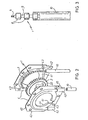
- Figure 2 is an exploded perspective view of the motion input casing, said casing being shown in an inverted position rotated through 180° with respect to that shown in Figure 1;
- Figure 3 is an enlarged view of part of one of the tube-encased portions of the flexible element.
- From said figures it can be seen that the invention comprises a flexible element 1 passing endlessly about two
sprocket wheels sprocket wheels sectional metal casings 4, 5. - As clearly shown in Figure 3, said flexible element comprises a stranded
metal cable 6, the ends of which are connected together by a metal joint 7. - A plurality of small coaxial
cylindrical bodies 8 constructed of a rigid synthetic material are fixed by direct thermoforming on to thecable 6, their opposing ends being in the shape of a spherical cap in order to facilitate their engagement with the toothing of saidsprocket wheels - Furthermore, in the case illustrated those portions of the
cable 6 lying between said bodies are covered with a thin synthetic coating 9, which is also directly formed on thecable 6. - The joint 7 of the
cable 6 is equal to, and takes the place of, one of thebodies 8. - As shown in Figures 1 and 2, each
sectional casing 4, 5 comprises two opposing half-shells which contain a central hole and are formed by blanking/drawing a thin metal sheet, said half-shells being fixed together by clinching, this being done by bending a series ofperimetral lugs - Concentrically with the central hole of each half-shell there is also provided a
circular recess respective sprocket wheel circumferential groove 22. - This latter receives, practically as an exact fit, a circumferential lip 44 (Figure 2) which bounds the central hole of the corresponding half-shell, and acts as the support and guide element for said
sprocket wheel - In addition, from each
recess parallel ducts - As can be seen, the facing pairs of
said ducts tubes 10 to enable thetubes 10 to be fixed in the required configuration, whereas respective perimetral series of throughholes casings 4, 5. - As stated in the introduction, the described transmission unit is suitable for the most widespread applications because of its small overall size and the fact that it can assume configurations conforming to its connection housing, without this compromising its functionality.
- In this respect, the invention can be mounted in the illustrated flat configuration, with the
tubes 10 bowed inwards or outwards with respect to the axis of the flat ring shown in Figure 1, or thetubes 10 can be bent in many other directions, or twisted about themselves. - In the particular application shown in Figure 1, the invention is used for sliding a suitably guided
rack 12, for example associated with a sliding door or panel such as a side window of an automobile. - In order to slide said
rack 12, thesprocket wheel 3 is provided withinner toothing 13 for fitting into the groovedportion 14 of apinion assembly 15 which is provided at its opposite end with apinion gear 15 for engaging saidrack 12. - Said
pinion assembly 15 is locked axially on to the drivensprocket wheel 3 by aspring ring 17. - Finally, for rotating the
drive sprocket wheel 2, which itself controls the sliding of the flexible element 1, there is provided a smallreduction gear unit 18 of the helical gear-worm type, this latter being driven by a smallelectric motor 19. - The
sprocket wheel 2 andreduction gear unit 18 are fixed together axially by acoaxial bolt 20, and said elements are kinematically linked by way of a suitable friction gear (not shown), the driven element of which torsionally engages a series of equidistantradial blades 21 provided on the sprocket wheel 2 (Figure 1).
Claims (5)
Priority Applications (1)
| Application Number | Priority Date | Filing Date | Title |
|---|---|---|---|
| AT86200654T ATE44309T1 (en) | 1985-04-23 | 1986-04-17 | FLEXIBLE ELEMENT POWER TRANSMISSION UNIT FOR DRIVING ROTATABLE LINKS. |
Applications Claiming Priority (2)
| Application Number | Priority Date | Filing Date | Title |
|---|---|---|---|
| IT3484985U | 1985-04-23 | ||
| IT8534849U IT8534849V0 (en) | 1985-04-23 | 1985-04-23 | FLEXIBLE ELEMENT TRANSMISSION GROUP FOR SWIVELING OF REVOLVING BODIES IN GENERAL |
Publications (2)
| Publication Number | Publication Date |
|---|---|
| EP0199417A1 EP0199417A1 (en) | 1986-10-29 |
| EP0199417B1 true EP0199417B1 (en) | 1989-06-28 |
Family
ID=11240333
Family Applications (1)
| Application Number | Title | Priority Date | Filing Date |
|---|---|---|---|
| EP86200654A Expired EP0199417B1 (en) | 1985-04-23 | 1986-04-17 | Flexible-element transmission unit for driving rotary members |
Country Status (5)
| Country | Link |
|---|---|
| US (1) | US4767386B1 (en) |
| EP (1) | EP0199417B1 (en) |
| AT (1) | ATE44309T1 (en) |
| DE (1) | DE3664153D1 (en) |
| IT (1) | IT8534849V0 (en) |
Cited By (1)
| Publication number | Priority date | Publication date | Assignee | Title |
|---|---|---|---|---|
| CN111890306A (en) * | 2020-08-07 | 2020-11-06 | 中国建筑第八工程局有限公司 | Bolt fastening device and method for air pipe in narrow space |
Families Citing this family (13)
| Publication number | Priority date | Publication date | Assignee | Title |
|---|---|---|---|---|
| US4862757A (en) * | 1987-06-24 | 1989-09-05 | Dahl Frank L | Translatory drive linkage type of power transmission apparatus |
| DK490688A (en) * | 1988-09-02 | 1990-03-03 | Mercante Int As | DEVICE FOR POWER TRANSMISSION FROM A DRIVE SHAFT TO A DRIVE SHAFT |
| JPH02138067A (en) * | 1988-11-19 | 1990-05-28 | Tokai Kogyo Kk | Paper feed tractor |
| US5440944A (en) * | 1993-07-08 | 1995-08-15 | Chen; Tse-Hsing | Safety power window mechanism for all types of automobile |
| US5615577A (en) * | 1994-08-11 | 1997-04-01 | Chen; Tse-Hsing | Ultrathin transmission mechanism for all types of automobile power window |
| US5794478A (en) * | 1996-05-21 | 1998-08-18 | Chin-Yun Huang | Transmitting chain for an automobile electric window |
| US5810687A (en) * | 1996-08-15 | 1998-09-22 | Yang; Nan-Shan | Power window transmission |
| US5836843A (en) * | 1996-10-29 | 1998-11-17 | Richards Racing Products, Inc. | Brace for outer ends of variable pulley drive |
| US20020115512A1 (en) * | 2001-02-22 | 2002-08-22 | Mike Mishler | Wrapping connector driving device and drive unit provided with wrapping connector driving device |
| CN102226483A (en) * | 2011-05-25 | 2011-10-26 | 犹云 | Mechanical full-sealed remote driving device |
| US20150133247A1 (en) * | 2013-11-13 | 2015-05-14 | Shawn Watling | Snow mobile drive assembly |
| CA3086296C (en) * | 2017-12-20 | 2023-04-04 | Lutron Technology Company Llc | Semi-rigid chain assembly |
| US12065877B2 (en) | 2020-01-31 | 2024-08-20 | Lutron Technology Company Llc | Semi-rigid chain for a window treatment |
Family Cites Families (13)
| Publication number | Priority date | Publication date | Assignee | Title |
|---|---|---|---|---|
| DE585309C (en) * | 1933-10-02 | Albert Obermoser | Power transmission gear with rubber belts and pulleys | |
| US551811A (en) * | 1895-12-24 | Frederic a | ||
| GB189407146A (en) * | 1894-04-10 | 1894-05-19 | Alfred Marshall Moore | Improvements in Gear Case for Bicycles. |
| FR53931E (en) * | 1945-03-21 | 1947-01-13 | Mechanical transmission by mobile strings under flexible inextensible sheath with circular control by said strings acting by meshing | |
| FR1108374A (en) * | 1954-07-03 | 1956-01-12 | Transmission organ | |
| FR2171617A5 (en) * | 1972-02-09 | 1973-09-21 | Parveau Albert | |
| US3991594A (en) * | 1974-12-27 | 1976-11-16 | Goenner Albert O | Anti theft locking system |
| US4158402A (en) * | 1977-10-11 | 1979-06-19 | Orville Romans | Motorcycle chainguard and lubricator |
| US4214488A (en) * | 1977-10-27 | 1980-07-29 | Dynaloc Corporation | Positive drive system |
| CA1130101A (en) * | 1979-05-10 | 1982-08-24 | Peter Zisterer | Lock against theft for skis |
| JPS5843876A (en) * | 1981-09-05 | 1983-03-14 | 本田技研工業株式会社 | Mud guard device for chain in motorcycle |
| CH654084A5 (en) * | 1981-10-16 | 1986-01-31 | Feramatic Ag | DRIVE DEVICE WITH A BALL JOINT CHAIN. |
| DE3428963C2 (en) * | 1983-08-22 | 1996-08-29 | Sft Ag Spontanfoerdertechnik | Device for transmitting a rotary movement |
-
1985
- 1985-04-23 IT IT8534849U patent/IT8534849V0/en unknown
-
1986
- 1986-04-17 EP EP86200654A patent/EP0199417B1/en not_active Expired
- 1986-04-17 AT AT86200654T patent/ATE44309T1/en not_active IP Right Cessation
- 1986-04-17 DE DE8686200654T patent/DE3664153D1/en not_active Expired
- 1986-04-22 US US06854486 patent/US4767386B1/en not_active Expired - Lifetime
Cited By (1)
| Publication number | Priority date | Publication date | Assignee | Title |
|---|---|---|---|---|
| CN111890306A (en) * | 2020-08-07 | 2020-11-06 | 中国建筑第八工程局有限公司 | Bolt fastening device and method for air pipe in narrow space |
Also Published As
| Publication number | Publication date |
|---|---|
| US4767386B1 (en) | 1999-10-19 |
| ATE44309T1 (en) | 1989-07-15 |
| US4767386A (en) | 1988-08-30 |
| DE3664153D1 (en) | 1989-08-03 |
| EP0199417A1 (en) | 1986-10-29 |
| IT8534849V0 (en) | 1985-04-23 |
Similar Documents
| Publication | Publication Date | Title |
|---|---|---|
| EP0199417B1 (en) | Flexible-element transmission unit for driving rotary members | |
| US4829313A (en) | Drive system and filament for a twistable septum in a feedhorn | |
| US5284455A (en) | Shaft coupling having multiple rib connectors | |
| US3280509A (en) | Driving device for vehicle windows | |
| WO1982003110A1 (en) | Split pulley | |
| EP1284042B2 (en) | Driving unit | |
| US20180283076A1 (en) | Lifting device for vehicle tailgate and driving device thereof | |
| US20060273675A1 (en) | Hobby servo attachment mechanisms | |
| CN103228941B (en) | Rotary transfer apparatus and motor | |
| US5346420A (en) | Gearing and drive mechanism for construction toy system | |
| CN110030359B (en) | Harmonic reducer and robot joint driver | |
| EP0211687A1 (en) | A gear mechanism | |
| US7098562B2 (en) | Ambidextrous electronic window lift motor | |
| US20020006846A1 (en) | Rolling contact screw-and -nut transmission device, and linear actuator comprising this device | |
| US5145467A (en) | Geared motor for the drive of components, such as motor-vehicle accessories, particularly an opening roof | |
| US5423707A (en) | Motor installation for construction toy system | |
| US4227426A (en) | Device for longitudinal displacement of a flexible drive wire | |
| US3235248A (en) | Drive device and a method of producing the same | |
| US5106316A (en) | Clock spring | |
| GB2128875A (en) | Safety belt reel | |
| EP0724060B1 (en) | Window winder operated by unified kinematic chain | |
| CN213228278U (en) | Driving device and vehicle skylight | |
| GB2587078A (en) | Cover hood for a door or window drive | |
| CN220502333U (en) | External rotary joint and surgical robot | |
| CN107848100B (en) | Electric tool |
Legal Events
| Date | Code | Title | Description |
|---|---|---|---|
| PUAI | Public reference made under article 153(3) epc to a published international application that has entered the european phase |
Free format text: ORIGINAL CODE: 0009012 |
|
| AK | Designated contracting states |
Kind code of ref document: A1 Designated state(s): AT BE CH DE FR GB IT LI LU NL SE |
|
| 17P | Request for examination filed |
Effective date: 19870528 |
|
| 17Q | First examination report despatched |
Effective date: 19880629 |
|
| GRAA | (expected) grant |
Free format text: ORIGINAL CODE: 0009210 |
|
| AK | Designated contracting states |
Kind code of ref document: B1 Designated state(s): AT BE CH DE FR GB IT LI LU NL SE |
|
| REF | Corresponds to: |
Ref document number: 44309 Country of ref document: AT Date of ref document: 19890715 Kind code of ref document: T |
|
| ITF | It: translation for a ep patent filed | ||
| REF | Corresponds to: |
Ref document number: 3664153 Country of ref document: DE Date of ref document: 19890803 |
|
| ET | Fr: translation filed | ||
| PG25 | Lapsed in a contracting state [announced via postgrant information from national office to epo] |
Ref country code: LU Free format text: LAPSE BECAUSE OF NON-PAYMENT OF DUE FEES Effective date: 19900430 |
|
| PLBE | No opposition filed within time limit |
Free format text: ORIGINAL CODE: 0009261 |
|
| STAA | Information on the status of an ep patent application or granted ep patent |
Free format text: STATUS: NO OPPOSITION FILED WITHIN TIME LIMIT |
|
| 26N | No opposition filed | ||
| ITTA | It: last paid annual fee | ||
| EAL | Se: european patent in force in sweden |
Ref document number: 86200654.1 |
|
| REG | Reference to a national code |
Ref country code: GB Ref legal event code: IF02 |
|
| PGFP | Annual fee paid to national office [announced via postgrant information from national office to epo] |
Ref country code: AT Payment date: 20030411 Year of fee payment: 18 |
|
| PGFP | Annual fee paid to national office [announced via postgrant information from national office to epo] |
Ref country code: CH Payment date: 20030502 Year of fee payment: 18 |
|
| PG25 | Lapsed in a contracting state [announced via postgrant information from national office to epo] |
Ref country code: AT Free format text: LAPSE BECAUSE OF NON-PAYMENT OF DUE FEES Effective date: 20040417 |
|
| PG25 | Lapsed in a contracting state [announced via postgrant information from national office to epo] |
Ref country code: LI Free format text: LAPSE BECAUSE OF NON-PAYMENT OF DUE FEES Effective date: 20040430 Ref country code: CH Free format text: LAPSE BECAUSE OF NON-PAYMENT OF DUE FEES Effective date: 20040430 |
|
| REG | Reference to a national code |
Ref country code: CH Ref legal event code: PL |
|
| PGFP | Annual fee paid to national office [announced via postgrant information from national office to epo] |
Ref country code: NL Payment date: 20050403 Year of fee payment: 20 |
|
| PGFP | Annual fee paid to national office [announced via postgrant information from national office to epo] |
Ref country code: SE Payment date: 20050406 Year of fee payment: 20 |
|
| PGFP | Annual fee paid to national office [announced via postgrant information from national office to epo] |
Ref country code: FR Payment date: 20050408 Year of fee payment: 20 |
|
| PGFP | Annual fee paid to national office [announced via postgrant information from national office to epo] |
Ref country code: GB Payment date: 20050413 Year of fee payment: 20 |
|
| PGFP | Annual fee paid to national office [announced via postgrant information from national office to epo] |
Ref country code: DE Payment date: 20050414 Year of fee payment: 20 |
|
| PGFP | Annual fee paid to national office [announced via postgrant information from national office to epo] |
Ref country code: IT Payment date: 20050428 Year of fee payment: 20 |
|
| PGFP | Annual fee paid to national office [announced via postgrant information from national office to epo] |
Ref country code: BE Payment date: 20050609 Year of fee payment: 20 |
|
| PG25 | Lapsed in a contracting state [announced via postgrant information from national office to epo] |
Ref country code: GB Free format text: LAPSE BECAUSE OF EXPIRATION OF PROTECTION Effective date: 20060416 |
|
| PG25 | Lapsed in a contracting state [announced via postgrant information from national office to epo] |
Ref country code: NL Free format text: LAPSE BECAUSE OF EXPIRATION OF PROTECTION Effective date: 20060417 |
|
| REG | Reference to a national code |
Ref country code: GB Ref legal event code: PE20 |
|
| NLV7 | Nl: ceased due to reaching the maximum lifetime of a patent |
Effective date: 20060417 |
|
| EUG | Se: european patent has lapsed | ||
| BE20 | Be: patent expired |
Owner name: *SPAL S.R.L. Effective date: 20060417 |