EP0199390A1 - Dentist's angle piece with a device for illuminating the spot to be treated - Google Patents
Dentist's angle piece with a device for illuminating the spot to be treated Download PDFInfo
- Publication number
- EP0199390A1 EP0199390A1 EP86200468A EP86200468A EP0199390A1 EP 0199390 A1 EP0199390 A1 EP 0199390A1 EP 86200468 A EP86200468 A EP 86200468A EP 86200468 A EP86200468 A EP 86200468A EP 0199390 A1 EP0199390 A1 EP 0199390A1
- Authority
- EP
- European Patent Office
- Prior art keywords
- sleeve
- head part
- light bulb
- head
- electrical
- Prior art date
- Legal status (The legal status is an assumption and is not a legal conclusion. Google has not performed a legal analysis and makes no representation as to the accuracy of the status listed.)
- Withdrawn
Links
- 241000446313 Lamella Species 0.000 claims abstract description 12
- 229910052751 metal Inorganic materials 0.000 description 3
- 239000002184 metal Substances 0.000 description 3
- 238000005452 bending Methods 0.000 description 2
- 229910000838 Al alloy Inorganic materials 0.000 description 1
- 238000004026 adhesive bonding Methods 0.000 description 1
- 239000004020 conductor Substances 0.000 description 1
- 238000010276 construction Methods 0.000 description 1
- 239000000356 contaminant Substances 0.000 description 1
- 239000002826 coolant Substances 0.000 description 1
- 230000001419 dependent effect Effects 0.000 description 1
- 229910052736 halogen Inorganic materials 0.000 description 1
- 150000002367 halogens Chemical class 0.000 description 1
- 238000004519 manufacturing process Methods 0.000 description 1
- 239000013307 optical fiber Substances 0.000 description 1
- 230000000149 penetrating effect Effects 0.000 description 1
- 238000005476 soldering Methods 0.000 description 1
Images


Classifications
-
- A—HUMAN NECESSITIES
- A61—MEDICAL OR VETERINARY SCIENCE; HYGIENE
- A61C—DENTISTRY; APPARATUS OR METHODS FOR ORAL OR DENTAL HYGIENE
- A61C1/00—Dental machines for boring or cutting ; General features of dental machines or apparatus, e.g. hand-piece design
- A61C1/08—Machine parts specially adapted for dentistry
- A61C1/088—Illuminating devices or attachments
-
- A—HUMAN NECESSITIES
- A61—MEDICAL OR VETERINARY SCIENCE; HYGIENE
- A61C—DENTISTRY; APPARATUS OR METHODS FOR ORAL OR DENTAL HYGIENE
- A61C1/00—Dental machines for boring or cutting ; General features of dental machines or apparatus, e.g. hand-piece design
- A61C1/08—Machine parts specially adapted for dentistry
- A61C1/18—Flexible shafts; Clutches or the like; Bearings or lubricating arrangements; Drives or transmissions
Definitions
- the invention relates to a dental contra-angle handpiece with a device for illuminating the treatment site according to the preamble of patent claim 1.
- Dental handpieces are also already known in which a light source can be attached to the outside of the handpiece body (DE-AS 1,032,882 and 1,065,566); however, these arrangements are impractical and impede the work of the dentist.
- the invention has for its object to provide a dental contra-angle, in which a light source in the form of at least one miniature light bulb is installed and the electrical connection lines are arranged in a simple manner so that the construction of the contra-angle is not complicated and the dentist on the sleeve fastened headboard can be easily and conveniently replaced, a reliable electrical connection of the relevant connecting lines for the light source being ensured when the two parts are put together.
- the arrangement should be such that the dentist can easily switch the light source on and off as needed during the treatment.
- the contra-angle handpiece according to the invention is characterized by simple manufacture and assembly of its parts and reliable electrical connection of the miniature light bulb.
- the dentist can turn on this light bulb in a simple manner with the fingers of the hand holding the contra-angle handpiece, while the feed circuit is automatically interrupted when the push button is released and thus when the contra-angle handpiece is put down.
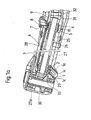
- the angle piece consists of a head part 27 with the angle piece head 27a, in which a treatment instrument (not shown) can be inserted by means of a fastening device 30, and of a sleeve 15 to which the head part 27 can be exchangeably fastened.
- the treatment instrument is driven in a known manner by a shaft 28 rotatably mounted in the head part 27, which is provided with a pinion 31 at its rear end.
- a further shaft 28a is rotatably mounted in the sleeve 15 and carries at its front end a pinion 32 which meshes with the pinion 31 of the shaft 28 mentioned above.
- the shaft 28a is driven by a small motor, not shown, which is accommodated in a connecting part which can be removably attached to the rear end of the sleeve 15.
- a tubular socket protruding from the front end of the small motor projects into the interior of the sleeve 15, and the shaft of the small motor engages in the fork 33 formed on the rear end of the shaft 28a, so that both shafts are coupled to one another in a rotationally fixed manner.
- the head part 27 sits in the outer sleeve part 15a of the sleeve 15, and is held firmly on the sleeve 15 by a retaining ring 25.
- the relative position of the two parts is determined by a pin 26 attached to the head part 27.
- a recess 2-9 is provided for a miniature light bulb 1, which is fastened in a conductive socket 1a by gluing or in some other way.
- This socket 1 is screwed into the body of the contra-angle head 27a and is provided with two slots 1c on its outer end face, so that it can be screwed or unscrewed with the aid of a suitable screwdriver. In this way, the light bulb 1 can be easily replaced.
- the inclination of the recess 29 with respect to the axis of the instrument is such that the light from the light bulb 1 used is directed at the outer end of the instrument, that is to say at the treatment site.
- the circumference of the bulb base, which forms the ground pole is in contact, for example by soldering, with the socket 1a, which in turn is in conductive connection with the body of the body made of metal and forming the ground line of the head part 27.
- the center contact 1b, forming the other pole, of the incandescent lamp base lies against a metallic ring 2, which is fastened on the circumference of an insulating support 3, which forms the front bearing of the shaft 28 or serves to hold such a bearing.
- This metallic ring 2 is connected by an insulated wire 4 to a further metallic ring 5 which is fastened on an insulating carrier 6; this carrier 6 forms the rear bearing of the shaft 28 or serves to hold such a bearing.
- the two ends of the wire 4 are soldered to the rings 2 and 5.
- the rear metallic ring 5 can, when the head part 27 is connected to the sleeve 15, be connected to an elastic contact in the form of a spring lamella 9, the rear end of which sits inside the sleeve 15 in an insulating carrier 10, which in turn is electrically connected to the conductive body of an inner sleeve part 11 of the sleeve 15 is pressed.
- This spring plate 9 extends axially within the sleeve 15 and in the region of its connection to the head part 27 and is arranged such that its front end is at a small radial distance from the ring 5.
- a switch 7 formed by a push button passes through an opening in the outer sleeve part 15a of the sleeve 15 in the region of the front end of the spring plate 9.
- This push button is and can be moved radially in a bushing 8 which is pressed into the aforementioned opening of the outer sleeve part 15a normally pressed into its raised idle state by the elastic force of the spring lamella 9, in which the spring lamella 9, as shown in FIG. 1 a for the right half of the switch 7, is lifted off the metallic ring 5 and the circuit for the light bulb 1 is thus interrupted.
- the spring lamella 9 thus functions not only as an electrical conductor, but also as a return spring for the switch 7.
- the head of the push button covers the socket 8 in order to prevent contaminants from penetrating into the angle piece.
- the dentist By pressing the push button with the fingers of his hand holding the contra-angle handpiece, the dentist brings the correspondingly curved spring lamella 9 into contact with the metallic ring 5, as shown for the left half of the switches 7, and thereby turns on the light bulb 1.
- the button When the button is released, the light bulb is automatically switched off. In this way, it is avoided that the light bulb is constantly switched on when the contra-angle handpiece is in operation and, if battery supply is provided, the battery is unnecessarily discharged. The dentist can therefore only temporarily switch on the light bulb 1 if required.
- the disadvantage is also avoided that the circuit remains closed when the elbow is put down; rather, the switch-off of the light bulb is automatically ensured when the contra-angle handpiece is put down.
- the light bulb but can "also be turned on when needed if the instrument driving motor is not in operation, which is very important to inspect the treatment site.
- the spring lamella 9 is electrically connected to an electrically conductive slip ring 21, which forms part of the rear surface of the sleeve, by means of a wire 23 soldered to it, which is surrounded by an insulating sleeve and extends in a groove provided on an inner sleeve part 14 of the sleeve 15 15 forms and concentrically surrounds the sleeve axis.
- the ground line of the light bulb circuit is formed by the two inner sleeve parts 11 and 14, which consist of a conductive metal and are mounted within the sleeve 15.
- the sleeve part 11 is pressed into the sleeve part 14, which in turn sits with slight friction in the outer sleeve part 15a and is fastened by a rear nut 16, a pin 17 engaging in an axially parallel opening of the outer sleeve part 15a for a defined, rotationally fixed connection of the two sleeve parts worries.
- the inner sleeve part 11 two bearings 12 and 13 are mounted for the shaft 28a.
- a channel for the passage of a coolant is provided in the inner sleeve part 11, which channel is closed in the example considered by a metallic plug 11.
- the outer sleeve part 15a consists, for example, of an aluminum alloy.
- an elastic contact 24 in the form of an axially extending conductive pin is provided, the rear end of which is clamped in the sleeve part 11 and the front region thereof is angled in such a way that it rests with sufficient elastic pretension, that is, with a corresponding bend, constantly on an inclined surface of the body of the head part 27. This ensures perfect electrical contact.
- the contra-angle described is characterized by simple and reliable electrical connections between its two parts, which can be quickly separated and assembled by the dentist in a simple manner by pulling the head part 27 out of the sleeve 15 or simply by bending the safety ring 25 this sleeve 15 can be pushed in, which can be used in combination with different head parts.
- the sleeve 15 can be disassembled by unscrewing the nut 16.
- the angle piece described is preferably set up to be driven by a small electric or compressed air motor.
- This small motor is accommodated in a connecting part, which can be attached to the rear end of the sleeve 5 and is provided for connecting the circuit of the light bulb 1 to a power source with two pin-shaped contacts 19 and 22 (Fig. 1b), which under the action of springs be pressed against the two slip rings 18 and 21 of the sleeve 15.
- the power source for the light bulb 1 can consist of preferably rechargeable batteries, which are accommodated in the connecting part and whose poles are electrically connected to the pin-shaped contacts 19 and 22.
- the light bulb 1 can also be supplied by an external power source, to which the elbow is connected via lines which run through the connecting part and through the supply hose, in which the supply lines for the small motor are also housed.
- the angle piece can also be set up for a conventional drive by an external motor using a belt and roller system; in this case, the connector part having the pin-shaped contacts 19 and 22 contains the parts serving to transmit the movement and the battery.
Abstract
Das Winkelstück ist mit wenigstens einer im Winkelstückkopf (27a) auswechselbar angeordneten Miniatur-Glühlampe (1) ausgerüstet und hat eine Kopfteil (27), das abnehmbar an einer Hülse (15) befestigt ist. Eine in dieser Hülse angeordnete Federlamelle (9), die einen elektrischen Kontakt bildet, erstreckt sich axial im Bereich der Verbindungsstelle zwischen Kopfteil (27) und Hülse (15) und befindet sich normalerweise im radialen Abstand von einem festen elektrischen Kontakt in Form eines metallischen Ringes (5) am hinteren Ende des Kopfteils (27). Dieser Ring (5) sitzt auf einem Träger (6), der ein Lager für die im Kopfteil (27) montierte Welle (28) bildet. Ein elektrischer Druckknopf-Schalter (7) ist in einer Oeffnung des Mantels der Hülse (15) radial verschiebbar und presst die Federlamelle (9) beim Eindrücken gegen den festen Kontakt (5), wodurch der Stromkreis für die Glühbirne (1) geschlossen wird. Beim Loslassen des Druckknopfes hebt die gleichzeitig als Rückstellfeder wirkende Federlamelle (9) vom festen Kontakt (5) ab und öffnet den Schalter. Auf diese Weise lässt sich die Glühbirne (1) leicht bei Bedarf mit den Fingern der das Winkelstück haltenden Hand einschalten.The angle piece is equipped with at least one miniature incandescent lamp (1) which is interchangeably arranged in the angle piece head (27a) and has a head part (27) which is removably attached to a sleeve (15). A spring plate (9) arranged in this sleeve, which forms an electrical contact, extends axially in the region of the connection point between the head part (27) and the sleeve (15) and is normally located at a radial distance from a fixed electrical contact in the form of a metallic ring (5) at the rear end of the head part (27). This ring (5) sits on a carrier (6) which forms a bearing for the shaft (28) mounted in the head part (27). An electrical push button switch (7) can be moved radially in an opening of the casing of the sleeve (15) and presses the spring lamella (9) against the fixed contact (5) when pressed in, as a result of which the circuit for the light bulb (1) is closed. When the push button is released, the spring plate (9), which also acts as a return spring, lifts off the fixed contact (5) and opens the switch. In this way, the light bulb (1) can be easily switched on with the fingers of the hand holding the contra-angle hand if necessary.
Description
Die Erfindung bezieht sich auf ein zahnärztliches Winkelstück mit einer Einrichtung zur Beleuchtung der Behandlungsstelle gemäss dem Oberbegriff des Patentanspruchs 1.The invention relates to a dental contra-angle handpiece with a device for illuminating the treatment site according to the preamble of
Es ist bereits bekannt, zahnärztliche Handstücke mit einer Beleuchtungseinrichtung auszurüsten, deren Licht auf die Behandlungsstelle gerichtet ist und damit die Arbeit des Zahnarztes erleichtert.It is already known to equip dental handpieces with a lighting device, the light of which is directed onto the treatment site and thus makes the dentist's work easier.
In den europäischen Patentanmeldungen mit den Veröffentlichungsnummem 34 237 und 143 985 werden derartige zahnärztliche Handstücke beschrieben, in denen optische Fasern als Lichtleiter installiert sind, welche die verschiedenen Teile des Handstücks durchqueren und deren vordere, das Licht emittierende Enden in der Nähe des Handstückkopfs aus dem Handstückkörper austreten. Es ist jedoch schwierig, diese Enden der Lichtleiter in geeigneter Weise in Richtung auf die Behandlungsstelle zu orientieren, da sie wegen ihrer Brüchigkeit nur schwach gebogen werden können und der zulässige Biegungswinkel im allgemeinen nicht ausreicht, um die das Licht emittierenden Stirnflächen genau auf die Behandlungsstelle zu richten. Ausserdem erfordert eine derartige Anordnung, dass die Lichtleiter durchgehend, ohne Unterbrechung, bis zur hinteren Lichtquelle, im allgemeinen einer Halogenlampe, verlaufen, da jede Unterbrechung wenigstens 30% an Lichtintensität absorbieren würde. Die Notwendigkeit von durchgehend im Handstück verlaufenden Lichtleitern erschwert den Aufbau eines Winkelstücks mit leicht auswechselbarem Kopfteil.In the European patent applications with the publication numbers 34 237 and 143 985 such dental handpieces are described in which optical fibers are installed as light guides, which pass through the different parts of the handpiece and whose front, light-emitting ends near the handpiece head from the handpiece body emerge. However, it is difficult to appropriately orient these ends of the light guides towards the treatment site, because they are only weakly bent due to their fragility and the permissible bending angle is generally not sufficient to precisely direct the light-emitting end faces towards the treatment site judge. In addition, such an arrangement requires that the light guides run continuously, without interruption, to the rear light source, generally a halogen lamp, since each interruption would absorb at least 30% of the light intensity. The necessity of light guides running continuously in the handpiece makes it difficult to construct an angle piece with an easily replaceable head part.
Es sind auch bereits zahnärztliche Handstücke bekannt, bei denen eine Lichtquelle aussen am Handstückkörper befestigt werden kann (DE-AS 1.032.882 und 1.065.566); diese Anordnungen sind jedoch unpraktisch und behindern die Arbeit des Zahnarztes.Dental handpieces are also already known in which a light source can be attached to the outside of the handpiece body (DE-AS 1,032,882 and 1,065,566); however, these arrangements are impractical and impede the work of the dentist.
Der Erfindung liegt die Aufgabe zugrunde, ein zahnärztliches Winkelstück zu schaffen, in welchem eine Lichtquelle in Form wenigstens einer Miniaturglühbirne eingebaut ist und die elektrischen Anschlussleitungen auf einfache Weise so angeordnet sind, dass der Aufbau des Winkelstücks nicht kompliziert wird und der Zahnarzt das an der Hülse befestigte Kopfteil leicht und bequem auswechseln kann, wobei beim Zusammensetzen beider 'Teile eine zuverlässige elektrische Verbindung der betreffenden Anschlussleitungen für die Lichtquelle gewährleistet ist. Ausserdem soll die Anordnung so getroffen sein, dass der Zahnarzt während der Behandlung die Lichtquelle nach Bedarf leicht ein-und ausschalten kann.The invention has for its object to provide a dental contra-angle, in which a light source in the form of at least one miniature light bulb is installed and the electrical connection lines are arranged in a simple manner so that the construction of the contra-angle is not complicated and the dentist on the sleeve fastened headboard can be easily and conveniently replaced, a reliable electrical connection of the relevant connecting lines for the light source being ensured when the two parts are put together. In addition, the arrangement should be such that the dentist can easily switch the light source on and off as needed during the treatment.
Diese Aufgabe wird erfindungsgemäss durch die im Patentanspruch 1 angegebenen Merkmale gelöst.According to the invention, this object is achieved by the features specified in
Das Winkelstück nach der Erfindung zeichnet sich durch eine einfache Fertigung und Montage seiner Teile und einen zuverlässigen elektrischen Anschluss der Miniaturglühbirne aus. Ausserdem kann der Zahnarzt diese Glühbirne auf einfache Weise mit den Fingern der das Winkelstück haltenten Hand einschalten, während der Speisestromkreis automatisch beim Loslassen des Druck knopfes und damit beim Ablegen des Winkelstücks unterbrochen wird.The contra-angle handpiece according to the invention is characterized by simple manufacture and assembly of its parts and reliable electrical connection of the miniature light bulb. In addition, the dentist can turn on this light bulb in a simple manner with the fingers of the hand holding the contra-angle handpiece, while the feed circuit is automatically interrupted when the push button is released and thus when the contra-angle handpiece is put down.
Zweckmässige Ausgestaltungen des Winkelstücks nach der Erfindung ergeben sich aus den abhängigen Patentansprüchen.Appropriate configurations of the contra-angle handpiece according to the invention result from the dependent patent claims.
Die Erfindung wird an Hand der Zeichnung an einem Ausführungsbeispiel näher erläutert. Es zeigen :
- Fig. 1a den vorderen Teil eines Winkelstücks, im Längsschnitt,
- Fig. 1 b den hinteren Teil dieses Winkelstücks, im Längsschnitt, und
- Fig. 2 eine Draufsicht auf die rückwärtige Fläche des Winkelstücks im Sinne des
Pfeils 11 nach Fig. 1b.
- 1a, the front part of an elbow, in longitudinal section,
- Fig. 1 b the rear part of this elbow, in longitudinal section, and
- Fig. 2 is a plan view of the rear surface of the elbow in the direction of
arrow 11 of Fig. 1b.
Nach den Figuren 1 und 2 besteht das Winkelstück aus einem Kopfteil 27 mit dem Winkelstückkopf 27a, in welchem ein nicht dargestelltes Behandlungsinstrument mittels einer Befestigungseinrichtung 30 eingesetzt werden kann, und aus einer Hülse 15, an welcher das Kopfteil 27 auswechselbar befestigt werden kann. Das Behandlungsinstrument wird in bekannter Weise durch eine drehbar im Kopfteil 27 gelagerte Welle 28 angetrieben, die an ihrem hinteren Ende mit einem Ritzel 31 versehen ist. In der Hülse 15 ist eine weitere Welle 28a drehbar gelagert, die an ihrem vorderen Ende ein mit dem Ritzel 31 der erst erwähnten Welle 28 kämmendes Ritzel 32 trägt. Die Welle 28a wird im betrachteten Beispiel durch einen nicht dargestellten Kleinmotor angetrieben, der in einem Anschlussteil untergebracht ist, welches abnehmbar am hinteren Ende der Hülse 15 befestigt werden kann. In diesem Falle ragt eine am vorderen Ende des Kleinmotors vorstehende rohrförmige Buchse ins Innere der Hülse 15 hinein, und die Welle des Kleinmotors greift in die am hinteren Ende der Welle 28a angeformte Gabel 33 ein, so dass beide Wellen drehfest miteinander gekuppelt sind.According to FIGS. 1 and 2, the angle piece consists of a
Das Kopfteil 27 sitzt im äusseren Hülsenteil 15a der Hülse 15, und wird durch einen Sicherungsring 25 fest an der Hülse 15 gehalten. Die relative Lage beider Teile ist dabei durch einen am Kopfteil 27 angebrachten Stift 26 festgelegt. Im Körper des Winkelstückkopfs 27a ist eine Ausnehmung 2-9 für eine Miniaturglühbirne 1 vorgesehen, die in einer leitenden Fassung 1a durch Kleben oder auf andere Weise befestigt ist. Diese Fassung 1 ist in den Körper des Winkelstückkopfs 27a eingeschraubt und auf ihrer äusseren Stirnfläche mit zwei Schlitzen 1c versehen, so dass sie einfach mit Hilfe eines geeigneten Schraubenziehers eingeschraubt beziehungsweise ausgeschraubt werden kann. Auf diese Weise lässt sich die Glühbirne 1 leicht auswechseln.The
Die Neigung der Ausnehmung 29 in Bezug auf die Achse des Instruments ist so getroffen, dass das Licht der eingesetzten Glühbirne 1 auf das äussere Ende des Instruments, also auf die Behandlungsstelle gerichtet ist. Der Umfang des Glühbirnensockels, welcher den Masse-Pol bildet, ist, beispielsweise durch Löten, mit der Fassung 1 a in Kontakt, welche ihrerseits mit dem Körper des aus Metall gefertigten und die Masse-Leitung bildenden Körpers des Kopfteils 27 in leitender Verbindung steht. Der den anderen Pol bildende Mittelkontakt 1b des Glühlampensockels liegt an einem metallischen Ring 2 an, der auf dem Umfang eines isolierenden Trägers 3 befestigt ist, welcher das vordere Lager der Welle 28 bildet oder zum Halten eines derartigen Lagers dient. Dieser metallische Ring 2 ist durch einen isolierten Draht 4 mit einem weiteren metallischen Ring 5 verbunden, welcher auf einem isolierenden Träger 6 befestigt ist; dieser Träger 6 bildet das hintere Lager der Welle 28 oder aber dient zum Halten eines derartigen Lagers. Die beiden Enden des Drahtes 4 sind an den Ringen 2 und 5 angelötet.The inclination of the
Der hintere metalische Ring 5 kann, wenn das Kopfteil 27 mit der Hülse 15 verbunden ist, mit einem elastischen Kontakt in Form einer Federlamelle 9 verbunden werden, deren rückwärtiges Ende im Innern der Hülse 15 in einem isolierenden Träger 10 sitzt, welcher seinerseits in den elektrisch leitenden Körper eines inneren Hülsenteils 11 der Hülse 15 eingepresst ist. Diese Federlamelle 9 erstreckt sich axial innerhalb der Hülse 15 und im Bereich ihrer Verbindung mit dem Kopfteil 27 und ist derart angeordnet, dass sich ihr vorderes Ende im kleinen radialen Abstand vom Ring 5 befindet. Ein durch einen Druckknopf gebildeter Schalter 7 durchsetzt eine Oeffnung im äusseren Hülsenteil 15a der Hülse 15 im Bereich des vorderen Endes der Federlamelle 9. Dieser Druckknopf ist radial in einer Buchse 8 verschiebbar, die in die erwähnte Oeffnung des äusseren Hülsenteils 15a eingepresst ist, und wird normalerweise durch die elastische Kraft der Federlamelle 9 in seinen angehobenen Ruhezustand gedrückt, in welchem die Federlamelle 9, wie in Fig. 1a für die rechte Hälfte des Schalters 7 gezeigt, vom metallischen Ring 5 abgehoben und damit der Stromkreis für die Glühbirne 1 unterbrochen ist. Die Federlamelle 9 fungiert also nicht nur als elektrischer Leiter, sondern auch als Rückstellfeder für den Schalter 7. Der -Kopf des Druckknopfes überdeckt die Buchse 8, um ein Eindringen von Verunreinigungen in das Winkelstück zu verhindern.The rear
Indem der Zahnarzt mit den Fingern seiner das Winkelstück haltenden Hand den Druckknopf eindrückt, bringt er die entsprechend gebogene Federlamelle 9 mit dem metallischen Ring 5 in Berührung, wie für die linke Hälfte der Schalter 7 gezeigt, und schaltet dadurch die Glühbirne 1 ein. Beim Loslassen des Druckknopfes wird die Glühbirne automatisch abgeschaltet. Auf diese Weise wird vermieden, dass bei Betrieb des Winkelstücks die Glühbirne ständig eingeschaltet ist und, falls eine Batteriespeisung vorgesehen ist, die Batterie unnötig entladen wird. Der Zahnarazt kann also auf einfache Weise nur bei Bedarf die Glühbirne 1 vorübergehend einschalten. Auch wird der Nachteil vermieden, dass beim Ablegen des Winkelstücks der Stromkreis geschlossen bleibt; vielmehr ist die Abschaltung der Glühbirne beim Ablegen des Winkelstücks automatisch gewährleistet. Andererseits kann jedoch "die Glühbirne auch dann bei Bedarf eingeschaltet werden, wenn der das Instrument antreibende Motor nicht in Betrieb ist, was zur Inspektion der Behandlungsstelle sehr wichtig ist.By pressing the push button with the fingers of his hand holding the contra-angle handpiece, the dentist brings the correspondingly
Die Federlamelle 9 ist elektrisch durch einen an sie angelöteten Draht 23, der von einer lsolierhülle umgeben ist und in einer auf einem inneren Hülsenteil 14 der Hülse 15 angebrachten Nut verläuft, mit einem elektrisch leitenden Schleifring 21 verbunden, der einen Teil der rückwärtigen Fläche der Hülse 15 bildet und die Hülsenachse konzentrisch umgibt.The
Die Masseleitung des Glühbirnen-Stromkreises wird durch die beiden inneren Hülsenteile 11 und 14 gebildet, die aus einem leitenden Metall bestehen und innerhalb der Hülse 15 montiert sind. Das Hülsenteil 11 ist in das Hülsenteil 14 eingepresst, welches seinerseits mit schwacher Reibung im äusseren Hülsenteil 15a sitzt und durch eine hintere Mutter 16 befestigt ist, wobei ein in eine achsenparallele Oeffnung des äusseren Hülsenteils 15a eingreifender Stift 17 für eine definierte, drehfeste Verbindung beider Hülsenteile sorgt. Auf der rückwärtigen Fläche der Hülse 15 ist als Massekontakt ein weiterer Schleifring 18 in Form eines Metallrings angebracht, der auf den hinteren Bereich des Hülsenteils 14 aufgepresst ist, konzentrisch den anderen Schleifring 21 umgibt und einen isolierenden Ring 20 hält, der beide Schleifringe 18 und 21 voneinander isoliert und zur Befestigung des Schleifrings 21 dient.The ground line of the light bulb circuit is formed by the two
Im inneren Hülsenteil 11 sind zwei Lager 12 und 13 für die Welle 28a montiert. Ausserdem ist im inneren Hülsenteil 11 ein Kanal für den Durchgang eines Kühlmittels vorgesehen, wobei dieser Kanal im betrachteten Beispiel durch einen metallischen Stopfen 11 verschlossen ist. Das äussere Hülsenteil 15a besteht beispielsweise aus einer Aluminiumlegierung.In the
Um eine gute elektrische Verbindung zwischen dem leitenden Körper des Kopfteils 27 und dem inneren Hülsenteil 11 der Hülse 15 zu gewährleisten, ist ein elastischer Kontakt 24 in Form eines sich axial erstreckenden leitenden Stifts vorgesehen, dessen rückwärtiges Ende im Hülsenteil 11 eingespannt ist und dessen vorderer Bereich derart abgewinkelt ist, dass er mit einer hinreichenden elastischen Vorspannung, also unter entsprechender Biegung, ständig an einer Schrägfläche des Körpers des Kopfteils 27 anliegt. Auf diese Weise wird ein einwandfreier elektrischer Kontakt gewährleistet.In order to ensure a good electrical connection between the conductive body of the
Das beschriebene Winkelstück zeichnet sich durch einfache und zuverlässige elektrische Verbindungen zwischen seinen beiden Teilen aus, welche vom Zahnarzt auf einfache Weise rasch voneinander getrennt und zusammengesetzt werden können, indem das Kopfteil 27 durch einfachen Zug unter Biegung des Sicherheitsringes 25 aus der Hülse 15 herausgezogen beziehungsweise in diese Hülse 15 hineingeschoben werden kann, welche in Kombination mit verschiedenen Kopfteilen verwendbar ist. Ausserdem lässt sich die Hülse 15 durch Abschrauben der Mutter 16 zerlegen.The contra-angle described is characterized by simple and reliable electrical connections between its two parts, which can be quickly separated and assembled by the dentist in a simple manner by pulling the
Das beschriebene Winkelstück ist vorzugsweise dazu eingerichtet, durch einen elektrischen oder Druckluft-Kleinmotor angetrieben zu werden. Dieser Kleinmotor ist in einem Anschlussteil unterbracht, welches am rückwärtigen Ende der Hülse 5 befestigt werden kann und zum Anschluss des Stromkreises der Glühbirne 1 an eine Stromquelle mit zwei stiftförmigen Kontakte 19 und 22 (Fig. 1b) versehen ist, die unter der Wirkung von Federn gegen die beiden Schleifringe 18 und 21 der Hülse 15 gedrückt werden. Dadurch lässt sich das Anschlussteil mit dem Motor unter Aufrechterhaltung der elektrischen Verbindung frei gegenüber der Hülse 15 drehen. Die Stromquelle für die Glühbirne 1 kann aus vorzugsweise wieder aufladbaren Batterien bestehen, die im Anschlussteil untergebracht und deren Pole mit den stiftförmigen Kontakten 19 und 22 elektrisch verbunden sind. Andererseits kann die Glühbirne 1 auch von einer äusseren Stromquelle gespeist werden, an welche das Winkelstück über Leitungen angeschlossen ist, welche durch das Anschlussteil und durch den Versorgungs schlauch verlaufen, in welchem auch die Versorgungsleitungen für den Kleinmotor untergebracht sind.The angle piece described is preferably set up to be driven by a small electric or compressed air motor. This small motor is accommodated in a connecting part, which can be attached to the rear end of the
Das Winkelstück kann auch für einen herkömmlichen Antrieb durch einen äusseren Motor mit Hilfe eines Riemen-und Laufrollensystems eingerichtet sein; in diesem Falle enthält das die stiftförmigen Kontakte 19 und 22 aufweisende Anschlussteil die zur Uebertragung der Bewegung dienenden Teile und die Batterie.The angle piece can also be set up for a conventional drive by an external motor using a belt and roller system; in this case, the connector part having the pin-shaped
Claims (5)
Applications Claiming Priority (2)
| Application Number | Priority Date | Filing Date | Title |
|---|---|---|---|
| FR8505016A FR2579447A1 (en) | 1985-03-27 | 1985-03-27 | DENTAL HANDPIECE WITH CONTRA-ANGLE OR TURBINE PROVIDED WITH MEANS OF LIGHTING OF THE PLACE OF TREATMENT |
| FR8505016 | 1985-03-27 |
Publications (1)
| Publication Number | Publication Date |
|---|---|
| EP0199390A1 true EP0199390A1 (en) | 1986-10-29 |
Family
ID=9317873
Family Applications (1)
| Application Number | Title | Priority Date | Filing Date |
|---|---|---|---|
| EP86200468A Withdrawn EP0199390A1 (en) | 1985-03-27 | 1986-03-21 | Dentist's angle piece with a device for illuminating the spot to be treated |
Country Status (5)
| Country | Link |
|---|---|
| US (1) | US4680011A (en) |
| EP (1) | EP0199390A1 (en) |
| JP (1) | JPS61226033A (en) |
| BR (1) | BR8601307A (en) |
| FR (1) | FR2579447A1 (en) |
Cited By (1)
| Publication number | Priority date | Publication date | Assignee | Title |
|---|---|---|---|---|
| EP1927324A1 (en) * | 2006-11-30 | 2008-06-04 | W & H Dentalwerk Bürmoos GmbH | Medical handpiece with lighting device |
Families Citing this family (8)
| Publication number | Priority date | Publication date | Assignee | Title |
|---|---|---|---|---|
| DE3734862C2 (en) * | 1987-10-14 | 1993-10-21 | Kaltenbach & Voigt | Dental spray handpiece |
| JPH10337292A (en) * | 1997-06-09 | 1998-12-22 | Nakanishi:Kk | Dental hand piece |
| US6015290A (en) * | 1998-12-22 | 2000-01-18 | Rosenstatter; Otto | Dental handpiece |
| DK1154811T3 (en) | 1999-12-08 | 2005-01-10 | Union Medico | injecting |
| WO2007025636A1 (en) | 2005-08-27 | 2007-03-08 | Universität Zürich | Illumination device for a dental handpiece, use thereof and method for selective removal of a tooth colored intra-coronal restoration |
| DE102006051511A1 (en) * | 2006-10-31 | 2008-05-08 | Kaltenbach & Voigt Gmbh | Coupling between a medical handpiece part and a supply hose |
| US20080108010A1 (en) * | 2006-11-07 | 2008-05-08 | Wen-Hao Wang | Illuminator for a dental drill |
| US20100203468A1 (en) * | 2009-02-06 | 2010-08-12 | Jennifer Cha | Dental hand piece provided with a direction indicating unit |
Citations (7)
| Publication number | Priority date | Publication date | Assignee | Title |
|---|---|---|---|---|
| DE1065566B (en) * | 1955-10-03 | |||
| FR673955A (en) * | 1929-04-24 | 1930-01-22 | Lamp holder for medical examination | |
| FR1123034A (en) * | 1955-03-03 | 1956-09-17 | Contra-angle improvements | |
| DE1032882B (en) * | 1957-02-14 | 1958-06-26 | Alfred Maier Dipl Ing | Mouth lights, in particular for dental purposes |
| EP0034237A1 (en) * | 1980-02-18 | 1981-08-26 | Bien-Air, D. Mosimann | Dental instrument with handpiece |
| DE3322923A1 (en) * | 1983-06-25 | 1985-01-03 | Waldemar Weimer Chem.-Pharm. Fabrik GmbH, 7550 Rastatt | Injection syringe, especially for dental purposes, having an illumination device |
| EP0143985A1 (en) * | 1983-11-02 | 1985-06-12 | Siemens Aktiengesellschaft | Dental hand-piece assembly with light-transmitting means |
Family Cites Families (3)
| Publication number | Priority date | Publication date | Assignee | Title |
|---|---|---|---|---|
| JPS54115304A (en) * | 1978-02-28 | 1979-09-07 | Central Glass Co Ltd | Preparation of chlorotrifluoroethylene |
| IL67784A0 (en) * | 1983-01-30 | 1983-05-15 | Adimec Advanced Mechanics Ltd | Illumination means for dental drills |
| JPS59218147A (en) * | 1983-05-24 | 1984-12-08 | 株式会社吉田製作所 | Illumination mechanism of dental prosthesis |
-
1985
- 1985-03-27 FR FR8505016A patent/FR2579447A1/en not_active Withdrawn
- 1985-05-20 JP JP60106202A patent/JPS61226033A/en active Pending
-
1986
- 1986-03-21 EP EP86200468A patent/EP0199390A1/en not_active Withdrawn
- 1986-03-24 BR BR8601307A patent/BR8601307A/en unknown
- 1986-03-26 US US06/844,356 patent/US4680011A/en not_active Expired - Fee Related
Patent Citations (7)
| Publication number | Priority date | Publication date | Assignee | Title |
|---|---|---|---|---|
| FR673955A (en) * | 1929-04-24 | 1930-01-22 | Lamp holder for medical examination | |
| FR1123034A (en) * | 1955-03-03 | 1956-09-17 | Contra-angle improvements | |
| DE1065566B (en) * | 1955-10-03 | |||
| DE1032882B (en) * | 1957-02-14 | 1958-06-26 | Alfred Maier Dipl Ing | Mouth lights, in particular for dental purposes |
| EP0034237A1 (en) * | 1980-02-18 | 1981-08-26 | Bien-Air, D. Mosimann | Dental instrument with handpiece |
| DE3322923A1 (en) * | 1983-06-25 | 1985-01-03 | Waldemar Weimer Chem.-Pharm. Fabrik GmbH, 7550 Rastatt | Injection syringe, especially for dental purposes, having an illumination device |
| EP0143985A1 (en) * | 1983-11-02 | 1985-06-12 | Siemens Aktiengesellschaft | Dental hand-piece assembly with light-transmitting means |
Cited By (2)
| Publication number | Priority date | Publication date | Assignee | Title |
|---|---|---|---|---|
| EP1927324A1 (en) * | 2006-11-30 | 2008-06-04 | W & H Dentalwerk Bürmoos GmbH | Medical handpiece with lighting device |
| US8038439B2 (en) | 2006-11-30 | 2011-10-18 | W&H Dentalwerk Burmoos Gmbh | Medical handpiece with a lighting device |
Also Published As
| Publication number | Publication date |
|---|---|
| JPS61226033A (en) | 1986-10-07 |
| US4680011A (en) | 1987-07-14 |
| BR8601307A (en) | 1986-12-02 |
| FR2579447A1 (en) | 1986-10-03 |
Similar Documents
| Publication | Publication Date | Title |
|---|---|---|
| EP0173159B1 (en) | Coupling device for dental hand pieces | |
| DE1284392B (en) | Electrically powered toothbrush | |
| DE19702370A1 (en) | Dental handpiece with root channel length measuring function | |
| DE3119689A1 (en) | DENTAL HANDPIECE WITH ITS OWN ELECTRIC LIGHT SOURCE | |
| EP0199390A1 (en) | Dentist's angle piece with a device for illuminating the spot to be treated | |
| DE3537807A1 (en) | DENTAL DRILLING HANDPIECE | |
| DE202010008186U1 (en) | Led lamp | |
| DE694707C (en) | Liche hand or angle pieces with swivel joint | |
| DE3021852A1 (en) | RING LAMP UNIT | |
| DE19613681C2 (en) | Dental handpiece | |
| DE19952332A1 (en) | Drill | |
| EP0179473A2 (en) | Adapter for a single-base low-pressure discharge lamp | |
| EP0199391A1 (en) | Dental treatment apparatus | |
| EP0286790B1 (en) | Dental handpiece assembly with light transmitting means | |
| EP2774571B1 (en) | Dynamoelectric converter and medical, in particular dental device with a dynamoelectric converter | |
| DE20209254U1 (en) | Flashlight with a connecting device for connecting lamp contacts of a lamp unit with a housing and a battery unit | |
| AT389633B (en) | Attachment for exchangeable grip sleeves of dental handpieces | |
| EP3012511B1 (en) | Light with lamp | |
| DE1230880B (en) | Electric switch with sliding actuator | |
| DE3615059C2 (en) | Lighting unit for electrical switches | |
| WO2015018398A1 (en) | Luminaire | |
| DE2234300C2 (en) | Multipole electrical connection element between a prosthesis shaft and an attachable artificial limb | |
| EP0906645B1 (en) | Printed circuit board with socket and base for a small incandescent lamp | |
| DE1540156A1 (en) | Device for electrical supply and cooling of a motor for hand tools | |
| DE838631C (en) | Socket combination for electric light tubes with connection terminals and ignition relay |
Legal Events
| Date | Code | Title | Description |
|---|---|---|---|
| PUAI | Public reference made under article 153(3) epc to a published international application that has entered the european phase |
Free format text: ORIGINAL CODE: 0009012 |
|
| AK | Designated contracting states |
Kind code of ref document: A1 Designated state(s): AT CH DE FR GB IT LI SE |
|
| 17P | Request for examination filed |
Effective date: 19870312 |
|
| 17Q | First examination report despatched |
Effective date: 19880804 |
|
| STAA | Information on the status of an ep patent application or granted ep patent |
Free format text: STATUS: THE APPLICATION IS DEEMED TO BE WITHDRAWN |
|
| 18D | Application deemed to be withdrawn |
Effective date: 19881003 |
|
| RIN1 | Information on inventor provided before grant (corrected) |
Inventor name: BOINOT, JEAN-CLAUDE |