EP0199366B1 - Header assembly for deep fat frying cooking system - Google Patents
Header assembly for deep fat frying cooking system Download PDFInfo
- Publication number
- EP0199366B1 EP0199366B1 EP86105746A EP86105746A EP0199366B1 EP 0199366 B1 EP0199366 B1 EP 0199366B1 EP 86105746 A EP86105746 A EP 86105746A EP 86105746 A EP86105746 A EP 86105746A EP 0199366 B1 EP0199366 B1 EP 0199366B1
- Authority
- EP
- European Patent Office
- Prior art keywords
- casing
- header assembly
- accordance
- panel
- vent means
- Prior art date
- Legal status (The legal status is an assumption and is not a legal conclusion. Google has not performed a legal analysis and makes no representation as to the accuracy of the status listed.)
- Expired
Links
- 238000010411 cooking Methods 0.000 title claims description 60
- 238000004891 communication Methods 0.000 claims description 9
- 230000001154 acute effect Effects 0.000 claims description 4
- 239000000523 sample Substances 0.000 claims description 4
- 238000004904 shortening Methods 0.000 description 10
- 235000013305 food Nutrition 0.000 description 8
- 239000002184 metal Substances 0.000 description 5
- 238000000034 method Methods 0.000 description 5
- 238000010438 heat treatment Methods 0.000 description 3
- 230000002411 adverse Effects 0.000 description 2
- 238000001816 cooling Methods 0.000 description 2
- 241000251468 Actinopterygii Species 0.000 description 1
- 240000005856 Lyophyllum decastes Species 0.000 description 1
- 235000013194 Lyophyllum decastes Nutrition 0.000 description 1
- 244000061456 Solanum tuberosum Species 0.000 description 1
- 235000002595 Solanum tuberosum Nutrition 0.000 description 1
- 230000002860 competitive effect Effects 0.000 description 1
- 230000007423 decrease Effects 0.000 description 1
- 235000013410 fast food Nutrition 0.000 description 1
- 235000021453 onion ring Nutrition 0.000 description 1
- 229920000515 polycarbonate Polymers 0.000 description 1
- 239000004417 polycarbonate Substances 0.000 description 1
- 235000012015 potatoes Nutrition 0.000 description 1
- 238000002360 preparation method Methods 0.000 description 1
- 230000005855 radiation Effects 0.000 description 1
- 238000011084 recovery Methods 0.000 description 1
- 229910001220 stainless steel Inorganic materials 0.000 description 1
- 239000010935 stainless steel Substances 0.000 description 1
- 238000013022 venting Methods 0.000 description 1
- 239000002699 waste material Substances 0.000 description 1
- XLYOFNOQVPJJNP-UHFFFAOYSA-N water Substances O XLYOFNOQVPJJNP-UHFFFAOYSA-N 0.000 description 1
Images

Classifications
-
- A—HUMAN NECESSITIES
- A21—BAKING; EDIBLE DOUGHS
- A21B—BAKERS' OVENS; MACHINES OR EQUIPMENT FOR BAKING
- A21B5/00—Baking apparatus for special goods; Other baking apparatus
- A21B5/08—Apparatus for baking in baking fat or oil, e.g. for making doughnuts
-
- A—HUMAN NECESSITIES
- A21—BAKING; EDIBLE DOUGHS
- A21B—BAKERS' OVENS; MACHINES OR EQUIPMENT FOR BAKING
- A21B1/00—Bakers' ovens
- A21B1/02—Bakers' ovens characterised by the heating arrangements
- A21B1/24—Ovens heated by media flowing therethrough
Definitions
- the present invention relates generally to cooking devices and more particularly to a header assembly for such cooking devices which mounts a microprocessor controlled cooking computer or other heat sensitive cooking controls for cooking foods to a predetermined level of doneness.
- a cooking device which comprises a housing and a cooking control system mounted on the housing.
- the cooking device is provided with cooling channels which conduct cool air in along the bottom of the cooking control system, up along the back of the cooking control system and out over the top of the cooking control system.
- Still another object is to provide such a header assembly which may be installed as original equipment or retrofitted to existing equipment.
- a further object is to provide such a header assembly which may be readily and economically fabricated and will enjoy a long life in operation.
- the header assembly is provided with a casing defining an enclosure having an opening on one side thereof said opening being connected with said chamber by means of an opening in a wall of said housing, said casing further defining first, second and third vent systems therein, the first and second vent systems being spaced substantially vertically from each other.
- the header assembly further includes a shield mounted within the enclosure of the casing and separating the enclosure into first and second passageways.
- a cooking computer control system is mounted on the casing and extends into the second passageway. The first vent system and the opening of the casing are in communication with the first passageway while the second and third vent systems are in communication with the second passageway thereof.
- the casing includes front and bottom sheet metal panels with the first and second vent systems defined in the front panel of the casing while the third vent system is defined in the bottom panel thereof.
- the casing also includes a computer mounting panel extending between the front and bottom panels of the casing and the computer control system has a microprocessor controlled cooking computer mounted within the computer mounting panel. The lead of the temperature probe unit of the cooking computer extends through an aperture in the shield and into the cooking device.
- a top panel of the casing provides an overhang to protect the computer and extends from the front panel at an acute angle thereto.
- the computer mounting panel extends from the front wall at an obtuse angle thereto and the shield is angled to extend upwardly from the bottom wall to the front wall.
- FIG. 1 therein illustrated is a deep fat frying cooking device generally indicated by the numeral 10 and having a header assembly embodying the present invention and generally indicated by numeral 12.
- the deep fat frying cooking device 10 includes a shell-like sheet metal housing 14 having a generally rectangular configuration and including a pair of side walls 16, a front wall 18, a top wall 20 and a rear wall (not shown).
- the housing 14 defines a large chamber 22 ( Figure 4) and has a heated kettle 24 mounted therein holding cooking shortening 25 for cooking fried foods in a manner well known in the art.
- Column member 26 Mounted on the back portion of the top wall is column member 26 which may be adapted to support a pair of independently vertically movable basket support hangers and their associated baskets (neither is shown in the drawings) as is well known in the art.
- the cooking device 10 can be any commercially available gas or electric cooking device such as those sold under the tradenames Frymaster, Pitco or Vulcan.
- the assembly 12 has a sheet metal casing 28 having a generally rectangular configuration.
- the casing 28 is made up of an inclined front vent panel 30, an inclined computer mounting panel 31, a top panel 32, a bottom vent panel 34 and a pair of end caps 36.
- the elements 30, 34 and 36 are spot welded, riveted or otherwise secured together while the computer mounting panel 31 and the top panel 32 are releasably fastened to flanges on the front vent panel 30, bottom vent panel 34 and end caps 36 by fastening elements 38 and 40, respectively.
- first vent system generally indicated by numeral 42 and having a multiplicity of juxtaposed sets of three elongated vent openings 44.
- intermediate or second vent system Spaced below the first vent system 42 in the front panel 30 is an intermediate or second vent system generally indicated by numeral 46.
- the second vent system comprises a multiplicity of juxtaposed sets of two elongated vent openings 48 having configurations similar to vent openings 44.
- the bottom vent panel 34 is provided with a lower or third vent system generally indicated by numeral 50 having a multiplicity of openings 52.
- the openings 52 of the third vent system 50 are arranged in rows forming a rectangular pattern in the bottom panel 34 of the casing 28. The pattern is equidistant from the end caps 36 but its longitudinal centerline is spaced slightly forward of the longitudinal centerline of the bottom panel 34.
- the computer mounting panel 31 has an on/off switch 54, heat indicator light 56 and a microprocessor controlled cooking computer 58 mounted thereon.
- the on/ off switch 54 offers manual control of the input of suitable electrical energy from a transformer 59 to the computer 58 by means of a suitable electrical connection (not shown).
- the heat indicator light 56 indicates the operating condition of the cooking device 10.
- the sheet metal casing 28 with its computer mounting panel 31 can be adapted to mount other electrical components (not shown) as may be necessary.
- the cooking computer 58 can be any commercially available cooking computer.
- the computer illustrated is Model 821 manufactured and sold under the trademark Fastron @ by Food Automation-Service Techniques, Inc. located and doing business at 905 Honeyspot Road, Stratford, Connecticut. While the operation and structuring of this particular computer is not critical to the invention, these characteristics will be described briefly for the purposes of completeness.
- the computer has a polycarbonate oil-resistant front face plate 55 and a brushed stainless steel chassis 59 ( Figure 4).
- the computer 58 is microprocessor controlled eight product computer and has an automatic light emitting diode time countdown display 60 which displays the time left in the cooking cycle in minutes and seconds.
- the display 60 also has the capability of displaying the temperature of the shortening and other operational signals.
- control selectors 62 Located below the display 60 are eight touch activated control selectors 62 (labelled 1-8) with their associated light emitting diode status indicators 64.
- the control selectors 62 are utilized by the operator to start/cancel cook cycles and to silence audible computer warning alarms.
- the individual status indicators 64 are illuminated when their associated control selectors 62 are activated.
- live touch actuated computer control keys 66 At bottom of the computer 58 are live touch actuated computer control keys 66 which facilitate the control and operation of the computer 58 by the user.
- top panel 32 of the header assembly 12 is secured to the inclined front vent panel 30 at an acute angle while the inclined computer mounting panel 31 is mounted to the front vent panel 30 at an obtuse angle. Accordingly, the front face of the panel 30 inclines downwardly while the front face of the panel 31 and, therefore, the computer 58 inclines uwpardly to facilitate the viewing thereof by the operator. Furthermore, top panel 32 overhangs the computer 58 and protects it from heated shortening which may spill from the kettle due to cooking or handling of the food items.
- the casing 28 of the header assembly 12 defines an enclosure 68 having an opening 70 on one side thereof.
- the shield 72 separates the enclosure 68 into two separate passageways 74 and 76.
- the first passageway 74 is in communication with the opening 70 and the first vent system 42 while the second passageway is in communication with the second and third vent systems 46 and 50.
- the header assembly 12 is mounted on the front wall 18 of the cooking device 10 which has an opening 78 therein.
- the opening 78 in the front wall 18 is substantially coextensive with the opening 70 of the casing 28. Accordingly, the enlarged chamber 22 of the cooking device 10 is in communication with the first vent system 42 whereby air within the chamber 22 is provided with an exit to the exterior of the cooking device 10 and the header assembly 12 through the openings 70 and 78, the passageway 74 and the first vent system 42.
- a temperature probe unit 80 Extending from the kettle through the openings 70 and 78 and the shield 72 into the second passageway 76 to the computer 58 is a temperature probe unit 80 which senses the temperature of the cooking shortening 25. This information is relayed to the computer 58 for use during the cooking process.
- the chassis 57 of the computer 58 is mounted on the inclined mounting panel 31 and is disposed in the second passageway 76.
- a 115-volt electrical supply line 82 extends through the shield 72 and is electrically connected through the transformer 59 to supply power to the computer 58.
- the shortening 25 in the kettle 24 is heated to cooking temperature, often 350°F or higher, by a heating unit (notshown) within the chamber 22 adjacent to kettle.
- the heated kettle 24 and operation of the heating unit raises the temperature of the air within the large chamber 22 and creates convection air currents therein indicated by numeral 84.
- the heated air flows upwardly through the openings 70 and 78, the passageway 74 and the first vent system 42 to the exterior of the cooking device 10 and header assembly 12.
- This air flow 84 through the header assembly and out the upper vent system 42 draws air from the second passageway through the second and third venting systems 46,50 creating a second airflow path designated by the numeral 86.
- This second air flow draws cool air from the exterior of the cooking device 10 and header assembly 12 pastthe cooking computer 58 thereby cooling the same and keeping the air temperature within the passageway below the maximum critical temperature of the computer 58.
- the second air flow 86 is also produced partially by heat generated by operation of the computer 57 and/or convection and radiation heating of the shield 72 from the air flow 84 and the heated kettle 24.
- the header assembly can be modified to be mounted or commercially available ovens as will be recognized by those skilled in the art.
- the header assembly of the present invention decreases temperature of environment of the cooking computer, thereby improving the service life expectancy thereof.
Landscapes
- Life Sciences & Earth Sciences (AREA)
- Engineering & Computer Science (AREA)
- Food Science & Technology (AREA)
- Chemical & Material Sciences (AREA)
- Oil, Petroleum & Natural Gas (AREA)
- Frying-Pans Or Fryers (AREA)
- Commercial Cooking Devices (AREA)
- Cookers (AREA)
Description
- The present invention relates generally to cooking devices and more particularly to a header assembly for such cooking devices which mounts a microprocessor controlled cooking computer or other heat sensitive cooking controls for cooking foods to a predetermined level of doneness.
- Conventional deep fat frying techniques have been used by restaurants, "fast-food" franchises and the like to prepare various fried food items such as french fried potatoes, fried chicken, breaded onion rings, fried fish fillets, etc. Generally, these items are fried in deep fat frying devices having heated wells or kettles for holding the cooking shortening and a basket system for retaining the food items in the heated shortening during the cooking process.
- In the highly competitive foodservice market, it is essential that the above-noted food items are cooked consistently to a predetermined level of doneness. To eliminate the guesswork involved such preparation, solid-state modular computerized cooking control computers such as that disclosed in U.S. Patent 3,979,056 issued September 7, 1976 have been developed by Food Automation-Service Techniques. Inc. located and doing business in Stratford, Connecticut. These computers use a temperature probe system such as that disclosed in U.S. Patent 3,866,472 issued on February 18, 1975 to analyze the variables (shortening temperature; fryer efficiency and capacity; quantity of product; quantity and condition of shortening; fryer recovery rate; product temperature and water content) associated with deep fat frying to control the cooking and determine when the produce is cooked to the desired amount of doneness. These computers reduce product waste, increase product yield and improve customer satisfaction.
- One of the drawbacks of these cooking computers is their tendency to be adversely affected by the high temperature environment of the cooking device, i.e., the cooking kettles and shortening are operated at temperatures approaching four hundred and fifty degrees Fahrenheit which in turn raises the temperature of the fryer housing and the air therein. To protect the computers from these elevated temperatures, the computer modules have been mounted in dead air spaces and insulated from the cooking kettle and fryer housing as suggested by U.S. Patent No. 3,904,852 issued on September 9, 1975; however, the possbility remains that the temperature of the insulated computer module may increase above the maximum allowable ambient temperature of 160°F thereby adversely affecting its temperature sensitive components. Operating temperatures lower than the maximum allowable temperature are desirable for long life of these components and reliability of their operation.
- From US-A-4 228 730 a cooking device is known which comprises a housing and a cooking control system mounted on the housing. The cooking device is provided with cooling channels which conduct cool air in along the bottom of the cooking control system, up along the back of the cooking control system and out over the top of the cooking control system.
- It is an object of the present invention to provide a novel header assembly for use in a deep fat frying cooking device to protect its microprocessor controlled cooking computer from the high temperature operating environment.
- It is also an object to provide such an assembly which affords easy access to the control panel of the computer and allows the cooking computer to be removed for replacement or repair, if necessary.
- Still another object is to provide such a header assembly which may be installed as original equipment or retrofitted to existing equipment.
- A further object is to provide such a header assembly which may be readily and economically fabricated and will enjoy a long life in operation.
- It has now been found that the foregoing and related objects can be readily attained in a combination of a header assembly with a cooking device according to claim 1.
- The header assembly is provided with a casing defining an enclosure having an opening on one side thereof said opening being connected with said chamber by means of an opening in a wall of said housing, said casing further defining first, second and third vent systems therein, the first and second vent systems being spaced substantially vertically from each other. The header assembly further includes a shield mounted within the enclosure of the casing and separating the enclosure into first and second passageways. A cooking computer control system is mounted on the casing and extends into the second passageway. The first vent system and the opening of the casing are in communication with the first passageway while the second and third vent systems are in communication with the second passageway thereof.
- Desirably, the casing includes front and bottom sheet metal panels with the first and second vent systems defined in the front panel of the casing while the third vent system is defined in the bottom panel thereof. The casing also includes a computer mounting panel extending between the front and bottom panels of the casing and the computer control system has a microprocessor controlled cooking computer mounted within the computer mounting panel. The lead of the temperature probe unit of the cooking computer extends through an aperture in the shield and into the cooking device.
- Ideally, a top panel of the casing provides an overhang to protect the computer and extends from the front panel at an acute angle thereto. The computer mounting panel extends from the front wall at an obtuse angle thereto and the shield is angled to extend upwardly from the bottom wall to the front wall.
- The invention will be more fully understood when reference is made to the following detailed description taken in conjunction with the accompanying drawings.
-
- Figure 1 is a perspective view of a deep fat frying cooking device including a header assembly embodying the present invention;
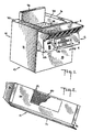
- Figure 2 is a bottom perspective view of the header assembly showing the third vent system in the bottom panel thereof;
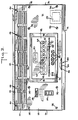
- Figure 3 is a front elevational view of the header assembly with a portion broken away to show internal structure; and
- Figure 4 is a fragmentary sectional view of the cooking device taken along the line 4-4 of Figure 1.
- Referring first to Figure 1, therein illustrated is a deep fat frying cooking device generally indicated by the
numeral 10 and having a header assembly embodying the present invention and generally indicated bynumeral 12. - The deep fat
frying cooking device 10 includes a shell-likesheet metal housing 14 having a generally rectangular configuration and including a pair ofside walls 16, afront wall 18, atop wall 20 and a rear wall (not shown). Thehousing 14 defines a large chamber 22 (Figure 4) and has a heatedkettle 24 mounted therein holding cooking shortening 25 for cooking fried foods in a manner well known in the art. Mounted on the back portion of the top wall iscolumn member 26 which may be adapted to support a pair of independently vertically movable basket support hangers and their associated baskets (neither is shown in the drawings) as is well known in the art. Thecooking device 10 can be any commercially available gas or electric cooking device such as those sold under the tradenames Frymaster, Pitco or Vulcan. - Turning now to Figure 3, the
header assembly 12 is illustrated in greater detail. Theassembly 12 has asheet metal casing 28 having a generally rectangular configuration. Thecasing 28 is made up of an inclinedfront vent panel 30, an inclinedcomputer mounting panel 31, atop panel 32, abottom vent panel 34 and a pair ofend caps 36. Theelements computer mounting panel 31 and thetop panel 32 are releasably fastened to flanges on thefront vent panel 30,bottom vent panel 34 andend caps 36 byfastening elements - Extending transversely across the upper portion of the
panel 28 is an upper or first vent system generally indicated bynumeral 42 and having a multiplicity of juxtaposed sets of threeelongated vent openings 44. Spaced below thefirst vent system 42 in thefront panel 30 is an intermediate or second vent system generally indicated bynumeral 46. The second vent system comprises a multiplicity of juxtaposed sets of twoelongated vent openings 48 having configurations similar tovent openings 44. - The
bottom vent panel 34 is provided with a lower or third vent system generally indicated bynumeral 50 having a multiplicity ofopenings 52. As best seen in Figure 2, theopenings 52 of thethird vent system 50 are arranged in rows forming a rectangular pattern in thebottom panel 34 of thecasing 28. The pattern is equidistant from theend caps 36 but its longitudinal centerline is spaced slightly forward of the longitudinal centerline of thebottom panel 34. - Referring again to Figure 3, the
computer mounting panel 31 has an on/offswitch 54, heat indicator light 56 and a microprocessor controlledcooking computer 58 mounted thereon. The on/ offswitch 54 offers manual control of the input of suitable electrical energy from atransformer 59 to thecomputer 58 by means of a suitable electrical connection (not shown). The heat indicator light 56 indicates the operating condition of thecooking device 10. Thesheet metal casing 28 with itscomputer mounting panel 31 can be adapted to mount other electrical components (not shown) as may be necessary. - The
cooking computer 58 can be any commercially available cooking computer. The computer illustrated is Model 821 manufactured and sold under the trademark Fastron@ by Food Automation-Service Techniques, Inc. located and doing business at 905 Honeyspot Road, Stratford, Connecticut. While the operation and structuring of this particular computer is not critical to the invention, these characteristics will be described briefly for the purposes of completeness. - The computer has a polycarbonate oil-resistant
front face plate 55 and a brushed stainless steel chassis 59 (Figure 4). Thecomputer 58 is microprocessor controlled eight product computer and has an automatic light emitting diode time countdown display 60 which displays the time left in the cooking cycle in minutes and seconds. The display 60 also has the capability of displaying the temperature of the shortening and other operational signals. - Located below the display 60 are eight touch activated control selectors 62 (labelled 1-8) with their associated light emitting
diode status indicators 64. Thecontrol selectors 62 are utilized by the operator to start/cancel cook cycles and to silence audible computer warning alarms. Theindividual status indicators 64 are illuminated when their associatedcontrol selectors 62 are activated. At bottom of thecomputer 58 are live touch actuatedcomputer control keys 66 which facilitate the control and operation of thecomputer 58 by the user. - Turning now to Figure 4, the
top panel 32 of theheader assembly 12 is secured to the inclinedfront vent panel 30 at an acute angle while the inclinedcomputer mounting panel 31 is mounted to thefront vent panel 30 at an obtuse angle. Accordingly, the front face of thepanel 30 inclines downwardly while the front face of thepanel 31 and, therefore, thecomputer 58 inclines uwpardly to facilitate the viewing thereof by the operator. Furthermore,top panel 32 overhangs thecomputer 58 and protects it from heated shortening which may spill from the kettle due to cooking or handling of the food items. - As also seen in Figure 4, the
casing 28 of theheader assembly 12 defines anenclosure 68 having an opening 70 on one side thereof. Mounted within theenclosure 68 between and spot welded to thebottom panel 34 and thefront vent panel 30 is an angled sheetmetal shield element 72. Theshield 72 separates theenclosure 68 into twoseparate passageways first passageway 74 is in communication with the opening 70 and thefirst vent system 42 while the second passageway is in communication with the second andthird vent systems - The
header assembly 12 is mounted on thefront wall 18 of thecooking device 10 which has an opening 78 therein. The opening 78 in thefront wall 18 is substantially coextensive with the opening 70 of thecasing 28. Accordingly, theenlarged chamber 22 of thecooking device 10 is in communication with thefirst vent system 42 whereby air within thechamber 22 is provided with an exit to the exterior of thecooking device 10 and theheader assembly 12 through the openings 70 and 78, thepassageway 74 and thefirst vent system 42. - Extending from the kettle through the openings 70 and 78 and the
shield 72 into thesecond passageway 76 to thecomputer 58 is a temperature probe unit 80 which senses the temperature of the cooking shortening 25. This information is relayed to thecomputer 58 for use during the cooking process. It should be noted that the chassis 57 of thecomputer 58 is mounted on the inclined mountingpanel 31 and is disposed in thesecond passageway 76. In addition, it should be noted that a 115-voltelectrical supply line 82 extends through theshield 72 and is electrically connected through thetransformer 59 to supply power to thecomputer 58. - During normal operation, the shortening 25 in the
kettle 24 is heated to cooking temperature, often 350°F or higher, by a heating unit (notshown) within thechamber 22 adjacent to kettle. Theheated kettle 24 and operation of the heating unit raises the temperature of the air within thelarge chamber 22 and creates convection air currents therein indicated bynumeral 84. The heated air flows upwardly through the openings 70 and 78, thepassageway 74 and thefirst vent system 42 to the exterior of thecooking device 10 andheader assembly 12. Thisair flow 84 through the header assembly and out theupper vent system 42 draws air from the second passageway through the second andthird venting systems cooking device 10 andheader assembly 12pastthe cooking computer 58 thereby cooling the same and keeping the air temperature within the passageway below the maximum critical temperature of thecomputer 58. Thesecond air flow 86 is also produced partially by heat generated by operation of the computer 57 and/or convection and radiation heating of theshield 72 from theair flow 84 and theheated kettle 24. - The header assembly can be modified to be mounted or commercially available ovens as will be recognized by those skilled in the art.
- Thus, it can be seen from the foregoing detailed specification and attached drawing that the header assembly of the present invention decreases temperature of environment of the cooking computer, thereby improving the service life expectancy thereof.
- The preferred embodiment described above admirably achieves the objects of the invention; however, it will be appreciated that departures can be made by those skilled in the art without departing from the scope of the invention which is limited only by the following claims.
Claims (17)
Applications Claiming Priority (2)
| Application Number | Priority Date | Filing Date | Title |
|---|---|---|---|
| US06/727,399 US4610238A (en) | 1985-04-25 | 1985-04-25 | Header assembly for deep fat frying cooking system |
| US727399 | 1985-04-25 |
Publications (3)
| Publication Number | Publication Date |
|---|---|
| EP0199366A2 EP0199366A2 (en) | 1986-10-29 |
| EP0199366A3 EP0199366A3 (en) | 1987-03-11 |
| EP0199366B1 true EP0199366B1 (en) | 1990-07-11 |
Family
ID=24922491
Family Applications (1)
| Application Number | Title | Priority Date | Filing Date |
|---|---|---|---|
| EP86105746A Expired EP0199366B1 (en) | 1985-04-25 | 1986-04-25 | Header assembly for deep fat frying cooking system |
Country Status (4)
| Country | Link |
|---|---|
| US (1) | US4610238A (en) |
| EP (1) | EP0199366B1 (en) |
| CA (1) | CA1248772A (en) |
| DE (1) | DE3672518D1 (en) |
Families Citing this family (21)
| Publication number | Priority date | Publication date | Assignee | Title |
|---|---|---|---|---|
| USD306205S (en) | 1986-04-25 | 1990-02-20 | Aktiebolaget Electrolux | Protective cover for a fan of a convection oven |
| US5123337A (en) * | 1991-03-18 | 1992-06-23 | Vie De France Corporation | Sous vide reheating device |
| US5097759A (en) * | 1991-03-18 | 1992-03-24 | Vie De France Corporation | Sous vide reheating device |
| US5379685A (en) * | 1994-01-07 | 1995-01-10 | Black & Decker Inc. | Venting system for an electric toaster |
| US6573483B1 (en) * | 2000-03-15 | 2003-06-03 | The Holmes Group, Inc. | Programmable slow-cooker appliance |
| US20110114625A1 (en) * | 2009-11-16 | 2011-05-19 | Prince Castle, Inc | Food holding cabinet with self-aligning and addressable power supplies |
| US20110114618A1 (en) * | 2009-11-16 | 2011-05-19 | Prince Castle, Inc | Universal food holding cabinet with snap-in escutcheons |
| US20110114624A1 (en) * | 2009-11-16 | 2011-05-19 | Prince Castle, Inc | Food holding cabinet power supplies with downloadable software |
| US9003820B2 (en) | 2010-04-20 | 2015-04-14 | Prince Castle LLC | Point-of-use holding cabinet |
| US9068768B2 (en) | 2010-05-19 | 2015-06-30 | Prince Castle LLC | Refrigerated point-of-use holding cabinet with downloadable software |
| US8607587B2 (en) | 2010-05-19 | 2013-12-17 | Prince Castle LLC | Refrigerated point-of-use holding cabinet |
| US8522675B2 (en) | 2010-05-21 | 2013-09-03 | Prince Castle, LLC | Holding cabinet for separately heating food trays |
| KR101654725B1 (en) * | 2015-01-16 | 2016-09-06 | 엘지전자 주식회사 | cooking appliance |
| CN104814069B (en) * | 2015-05-26 | 2017-01-04 | 南通市乐悦实业有限公司 | Make the cooker racks of the pan of fritters of twisted dough |
| CN104957203B (en) * | 2015-07-02 | 2017-12-01 | 河源市探索人发明科技有限公司 | Frying apparatus applied to food |
| CN105725246B (en) * | 2016-01-29 | 2018-04-13 | 罗文锋 | Vacuumize steam-type automatic stirring and stir machine |
| US9980322B1 (en) | 2016-04-19 | 2018-05-22 | Prince Castle LLC | Multi-zone food holding bin |
| USD809326S1 (en) | 2016-04-19 | 2018-02-06 | Prince Castle LLC | Food holding bin |
| US9976750B1 (en) | 2016-04-20 | 2018-05-22 | Prince Castle LLC | Multi-zone food holding bin |
| CN108464321A (en) * | 2018-05-29 | 2018-08-31 | 安徽夏星食品有限公司 | It is in charge of oil charging structure on Fryer |
| US12029351B2 (en) | 2020-04-03 | 2024-07-09 | Marmon Foodservice Technologies, Inc. | Capactive touch universal holding bin |
Family Cites Families (8)
| Publication number | Priority date | Publication date | Assignee | Title |
|---|---|---|---|---|
| US2237795A (en) * | 1937-12-21 | 1941-04-08 | Edison General Elec Appliance | Electric range |
| US3217704A (en) * | 1964-03-24 | 1965-11-16 | Anetsberger Bros Inc | Deep fat production fryers |
| US3659578A (en) * | 1970-12-15 | 1972-05-02 | Whirlpool Co | Vent for a self-cleaning oven |
| US3779228A (en) * | 1971-03-29 | 1973-12-18 | Rinnai Kk | Cooling apparatus for an oven |
| JPS4881142A (en) * | 1972-01-31 | 1973-10-30 | ||
| US3904852A (en) * | 1975-02-03 | 1975-09-09 | Food Automation Service Tech | Deep fat frying cooking control module |
| US4241718A (en) * | 1978-04-03 | 1980-12-30 | White Consolidated Industries, Inc. | Range body cooling system |
| US4228730A (en) * | 1979-03-30 | 1980-10-21 | Restaurant Technology, Inc. | Automatic french fryer |
-
1985
- 1985-04-25 US US06/727,399 patent/US4610238A/en not_active Expired - Lifetime
-
1986
- 1986-04-25 EP EP86105746A patent/EP0199366B1/en not_active Expired
- 1986-04-25 DE DE8686105746T patent/DE3672518D1/en not_active Expired - Fee Related
- 1986-04-25 CA CA000507652A patent/CA1248772A/en not_active Expired
Also Published As
| Publication number | Publication date |
|---|---|
| EP0199366A3 (en) | 1987-03-11 |
| DE3672518D1 (en) | 1990-08-16 |
| EP0199366A2 (en) | 1986-10-29 |
| CA1248772A (en) | 1989-01-17 |
| US4610238A (en) | 1986-09-09 |
Similar Documents
| Publication | Publication Date | Title |
|---|---|---|
| US4644931A (en) | Header assembly for deep fat frying cooking system | |
| US4610238A (en) | Header assembly for deep fat frying cooking system | |
| CA2365023C (en) | Food grilling system for oven cavity with byproduct removal | |
| CA1160118A (en) | Ventilated gas range with modular cooking units | |
| US4508026A (en) | Basket moving mechanism for deep fat fryer | |
| CA2119239C (en) | Quick-cooking oven | |
| US6187359B1 (en) | Method and apparatus for baking foods in a barbeque grill | |
| US5272317A (en) | Food support shelf comprising metal grill with heater | |
| US11825988B2 (en) | Professional fryer | |
| US2856502A (en) | Cooking apparatus | |
| EP1878371B1 (en) | Toaster cum microwave oven | |
| US4574770A (en) | Cooking grill grease catcher | |
| US3095495A (en) | Food broiling device | |
| US2984730A (en) | Multi-purpose cooking unit | |
| US3938495A (en) | Grilling apparatus with supporting surface | |
| US6674051B2 (en) | Heater cloaking grill grate system for downdraft cooking appliance | |
| US5579680A (en) | Smokeless grill for indoor use | |
| US4566429A (en) | Cooking grid | |
| US5396832A (en) | Fryer protective covering | |
| US20030159592A1 (en) | Table mountable fryer | |
| CN217959756U (en) | Visible air frying pot and multifunctional pot | |
| KR20050076579A (en) | An electric heating cooker | |
| KR20200098022A (en) | Improved air fryer | |
| CN211299596U (en) | Multi-layer electric oven | |
| EP1680998A1 (en) | Cooking apparatus |
Legal Events
| Date | Code | Title | Description |
|---|---|---|---|
| PUAI | Public reference made under article 153(3) epc to a published international application that has entered the european phase |
Free format text: ORIGINAL CODE: 0009012 |
|
| AK | Designated contracting states |
Kind code of ref document: A2 Designated state(s): DE FR GB IT SE |
|
| PUAL | Search report despatched |
Free format text: ORIGINAL CODE: 0009013 |
|
| AK | Designated contracting states |
Kind code of ref document: A3 Designated state(s): DE FR GB IT SE |
|
| 17P | Request for examination filed |
Effective date: 19870722 |
|
| 17Q | First examination report despatched |
Effective date: 19881215 |
|
| GRAA | (expected) grant |
Free format text: ORIGINAL CODE: 0009210 |
|
| AK | Designated contracting states |
Kind code of ref document: B1 Designated state(s): DE FR GB IT SE |
|
| REF | Corresponds to: |
Ref document number: 3672518 Country of ref document: DE Date of ref document: 19900816 |
|
| ITF | It: translation for a ep patent filed | ||
| ET | Fr: translation filed | ||
| ITTA | It: last paid annual fee | ||
| PLBE | No opposition filed within time limit |
Free format text: ORIGINAL CODE: 0009261 |
|
| STAA | Information on the status of an ep patent application or granted ep patent |
Free format text: STATUS: NO OPPOSITION FILED WITHIN TIME LIMIT |
|
| 26N | No opposition filed | ||
| PGFP | Annual fee paid to national office [announced via postgrant information from national office to epo] |
Ref country code: FR Payment date: 19940317 Year of fee payment: 9 |
|
| PGFP | Annual fee paid to national office [announced via postgrant information from national office to epo] |
Ref country code: SE Payment date: 19940321 Year of fee payment: 9 |
|
| PGFP | Annual fee paid to national office [announced via postgrant information from national office to epo] |
Ref country code: GB Payment date: 19940324 Year of fee payment: 9 |
|
| PGFP | Annual fee paid to national office [announced via postgrant information from national office to epo] |
Ref country code: DE Payment date: 19940630 Year of fee payment: 9 |
|
| EAL | Se: european patent in force in sweden |
Ref document number: 86105746.1 |
|
| PG25 | Lapsed in a contracting state [announced via postgrant information from national office to epo] |
Ref country code: GB Effective date: 19950425 |
|
| PG25 | Lapsed in a contracting state [announced via postgrant information from national office to epo] |
Ref country code: SE Effective date: 19950426 |
|
| GBPC | Gb: european patent ceased through non-payment of renewal fee |
Effective date: 19950425 |
|
| PG25 | Lapsed in a contracting state [announced via postgrant information from national office to epo] |
Ref country code: FR Effective date: 19951229 |
|
| PG25 | Lapsed in a contracting state [announced via postgrant information from national office to epo] |
Ref country code: DE Effective date: 19960103 |
|
| EUG | Se: european patent has lapsed |
Ref document number: 86105746.1 |
|
| REG | Reference to a national code |
Ref country code: FR Ref legal event code: ST |
|
| PG25 | Lapsed in a contracting state [announced via postgrant information from national office to epo] |
Ref country code: IT Free format text: LAPSE BECAUSE OF NON-PAYMENT OF DUE FEES;WARNING: LAPSES OF ITALIAN PATENTS WITH EFFECTIVE DATE BEFORE 2007 MAY HAVE OCCURRED AT ANY TIME BEFORE 2007. THE CORRECT EFFECTIVE DATE MAY BE DIFFERENT FROM THE ONE RECORDED. Effective date: 20050425 |