EP0199263B1 - Valve de pilote pour freins - Google Patents
Valve de pilote pour freins Download PDFInfo
- Publication number
- EP0199263B1 EP0199263B1 EP86105189A EP86105189A EP0199263B1 EP 0199263 B1 EP0199263 B1 EP 0199263B1 EP 86105189 A EP86105189 A EP 86105189A EP 86105189 A EP86105189 A EP 86105189A EP 0199263 B1 EP0199263 B1 EP 0199263B1
- Authority
- EP
- European Patent Office
- Prior art keywords
- pressure
- brake
- port
- valve
- metered
- Prior art date
- Legal status (The legal status is an assumption and is not a legal conclusion. Google has not performed a legal analysis and makes no representation as to the accuracy of the status listed.)
- Expired - Lifetime
Links
Images

Classifications
-
- B—PERFORMING OPERATIONS; TRANSPORTING
- B60—VEHICLES IN GENERAL
- B60T—VEHICLE BRAKE CONTROL SYSTEMS OR PARTS THEREOF; BRAKE CONTROL SYSTEMS OR PARTS THEREOF, IN GENERAL; ARRANGEMENT OF BRAKING ELEMENTS ON VEHICLES IN GENERAL; PORTABLE DEVICES FOR PREVENTING UNWANTED MOVEMENT OF VEHICLES; VEHICLE MODIFICATIONS TO FACILITATE COOLING OF BRAKES
- B60T8/00—Arrangements for adjusting wheel-braking force to meet varying vehicular or ground-surface conditions, e.g. limiting or varying distribution of braking force
- B60T8/32—Arrangements for adjusting wheel-braking force to meet varying vehicular or ground-surface conditions, e.g. limiting or varying distribution of braking force responsive to a speed condition, e.g. acceleration or deceleration
- B60T8/34—Arrangements for adjusting wheel-braking force to meet varying vehicular or ground-surface conditions, e.g. limiting or varying distribution of braking force responsive to a speed condition, e.g. acceleration or deceleration having a fluid pressure regulator responsive to a speed condition
- B60T8/341—Systems characterised by their valves
-
- B—PERFORMING OPERATIONS; TRANSPORTING
- B60—VEHICLES IN GENERAL
- B60T—VEHICLE BRAKE CONTROL SYSTEMS OR PARTS THEREOF; BRAKE CONTROL SYSTEMS OR PARTS THEREOF, IN GENERAL; ARRANGEMENT OF BRAKING ELEMENTS ON VEHICLES IN GENERAL; PORTABLE DEVICES FOR PREVENTING UNWANTED MOVEMENT OF VEHICLES; VEHICLE MODIFICATIONS TO FACILITATE COOLING OF BRAKES
- B60T13/00—Transmitting braking action from initiating means to ultimate brake actuator with power assistance or drive; Brake systems incorporating such transmitting means, e.g. air-pressure brake systems
- B60T13/10—Transmitting braking action from initiating means to ultimate brake actuator with power assistance or drive; Brake systems incorporating such transmitting means, e.g. air-pressure brake systems with fluid assistance, drive, or release
- B60T13/12—Transmitting braking action from initiating means to ultimate brake actuator with power assistance or drive; Brake systems incorporating such transmitting means, e.g. air-pressure brake systems with fluid assistance, drive, or release the fluid being liquid
-
- B—PERFORMING OPERATIONS; TRANSPORTING
- B60—VEHICLES IN GENERAL
- B60T—VEHICLE BRAKE CONTROL SYSTEMS OR PARTS THEREOF; BRAKE CONTROL SYSTEMS OR PARTS THEREOF, IN GENERAL; ARRANGEMENT OF BRAKING ELEMENTS ON VEHICLES IN GENERAL; PORTABLE DEVICES FOR PREVENTING UNWANTED MOVEMENT OF VEHICLES; VEHICLE MODIFICATIONS TO FACILITATE COOLING OF BRAKES
- B60T15/00—Construction arrangement, or operation of valves incorporated in power brake systems and not covered by groups B60T11/00 or B60T13/00
- B60T15/02—Application and release valves
- B60T15/36—Other control devices or valves characterised by definite functions
Definitions
- This invention relates to a vehicle brake control system and, in particular, to a brake feel augmentation valve to be used in an aircraft skid control system.
- Prior state-of-the art vehicle skid control systems are described in the inventor's prior U.S. Patent Nos. 4,053,187, 4,130,322 (corresponding to the preamble of claim 1) and 4,260,198.
- the vehicle operator e.g., an airplane pilot
- the brake pedal is connected to a pressure metering valve which supplies hydraulic fluid to the brakes via a skid control valve.
- a skid control circuit monitors the output of a wheelspeed transducer to check for skid conditions. If a skid is detected, the skid control circuit sends a control signal to the skid control valve.
- the skid control valve will regulate the amount of hydraulic fluid the metering valve supplies to the brakes, and thereby control braking action to prevent skidding.
- a vehicle brake control system is provided with a brake feel augmentation valve, which controls the supply of hydraulic fluid to a brake pressure port by a constant source of hydraulic fluid in response to metered pressure from a pressure metering valve and feedback brake pressure.
- the brake feel augmentation valve comprises a pressure balancing spool valve with four ports.
- a first port receives the metered pressure hydraulic fluid and directs it to a second land of the spool.
- a second port receives hydraulic fluid from the constant source, and is opened and closed by a first land of the spool valve.
- a third port is positioned between the first and second lands, and supplies hydraulic fluid to the brakes.
- a fourth port is a hydraulic return port.
- the spool valve is also provided with a feedback channel which directs brake pressure fluid to the first land of of the spool. When the metered pressure is greater than the fedback brake pressure, the spool valve opens the first port to allow hydraulic fluid to be supplied to the brake pressure port from the constant source. When the metered pressure is equal to or less than the fedback brake pressure, the spool valve blocks the supply of hydraulic fluid to the brake pressure port from the constant source port.
- the return port receives fluid from the brake pressure port when the fedback brake pressure exceeds the metered pressure.
- the brake is filled by a constant source of hydraulic fluid, rather than the pressure metering valve.
- the filling of the brakes, and associated pressure drop, is isolated from the pressure metering valve and the pilot's brake pedal.
- the brake feel augmentation valve of the present invention is designed so that very little flow is required from the pressure metering valve to initiate brake filling. Therefore, immediate and continuous pressure feedback is available to the pressure metering valve for responsive pedal feel.
- the present invention improves braking characteristics, especially at low speeds, by overcoming the problem of acute forces on the brake pedal.
- the present invention is particularily useful in carbon brake systems, and also can be used to improve the performance of steel brake systems.
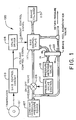
- FIG. 1 is a block diagram of a skid control system embodying the present invention.
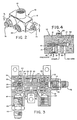
- FIG. 2 is a perspective view of a single wheel brake feel augmentation valve of the present invention.
- FIG. 3 is cross-sectional view taken along lines 3-3 of FIG. 2.
- FIG. 4 is a schematic view of the brake feel augmentation valve shown in FIG. 3.
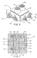
- FIG. 5 is a perspective view of a dual wheel brake feel augmentation valve of the present invention.
- FIG. 6 is a cross-sectional view taken along lines 6-6 of FIG. 5.
- FIG. 7 is a schematic view of the brake feel augmentation valve shown in FIG. 6.
- FIG. 1 shows the major components of a brake control system 100 embodying the present invention.
- the brake control system is an aircraft skid control system. All the components shown in FIG. 1, except for the single wheel brake feel augmentation valve 10, are standard components of aircraft antiskid systems which are well known in the art. A description of these components and their operation in a brake control system (not having a brake feel augmentation valve) can be found in U.S. Patent Nos. 3,768,873, 4,053,187, 4,130,322 and 4,260,198. The parts of these patents which describe these components and brake control system are incorporated by reference herein and made a part hereof.
- the single wheel brake feel augmentation valve 10 has four external ports which connect to various components of the skid control system.
- a first port 14 receives hydraulic fluid output from the pilot's pressure metering valve 115.
- a second port 16 receives hydraulic fluid from a constant hydraulic pressure source 107.
- the constant source 107 provides hydraulic fluid at a substantially constant system pressure of about 3000 P.S.I. It is possible for the actual system pressure to vary some without affecting the performance of the brake feel augmentation valve 10. In the present embodiment, BMS 3-11 or Skydrol 500 hydraulic fluid is used.
- a third port 18 supplies hydraulic fluid from the brake feel augmentation valve 10 to the brake cylinder 113 via the skid control valve 117.
- a fourth port 20 is connected to the system hydraulic return.
- FIG. 3 The structure and construction of a preferred embodiment of a single wheel brake feel augmentation valve 10 of the present invention is shown in FIG. 3.
- the four ports described above are bored into the valve housing 12.
- Filter fittings 22 are threaded into the inlets to the constant supply port 16 and the metered pressure port 14.
- a filter 24 (see FIG. 4) is located inside of each fitting 22 to prevent contaminants from entering the brake feel augmentation valve 10.
- These filter fittings are standard parts made by Mectron Industries, Inc.
- An o-ring 25 surrounds each filter fitting in the port inlet to provide a seal.
- a portion of the valve housing 12 is bored out to accept the cylindrical sleeve 26.
- a plurality of teflon retainers 27 and o-rings 28 are fitted around the circumference of the sleeve 26 to seal off the various ports of the valve.
- An axial bore 30 extends through the length of the sleeve 26. The sleeve is positioned within the valve housing 12 so that its radial bores 31a-c communicate with the constant source port 16, the brake fill port 18 and the return port 20, respectively.
- Both ends of the axial bore 30 are closed with end caps 32.
- the right end cap shown in FIG. 3 abuts the valve housing 12.
- the left end cap abuts a cover 34, and is provided with a threaded opening 33 to facilitate insertion of the end plug.
- the cover 34 threads into the valve housing 12 and holds the left end cap and sleeve 26 in place.
- a sealant (made by Dow Corning) is placed around the cover 34.
- a plurality of wrench holes 35 are provided in the cover 34 for turning the cover.
- a pressure balancing spool valve 40 fits within the axial bore 30 and slides laterally therein between the left and right end caps 32.
- the spool has a first land 41 and a second land 42. Both lands are provided with circumferential grooves 43 which equalize pressure around the spool and trap contamination.
- a feedback channel 45 extends between opposite sides of the first land 41.
- a first reduced orifice 46 is pressed into the feedback channel 45 at the first land 41.
- the reduced orifice 46 is intended to provide damping.
- a second reduced orifice 48 is pressed into an axial bore 49 which extends through the right end cap 32.
- the spool 40 is configured so that when no metered pressure is applied to the system, the first land 41 blocks the constant source port 16 via first radial bore 31a, and the second land blocks the return port 20 via third radial bore 31c.
- the control surface of the second land 42 is in constant communication with the metered pressure port 14 via the axial bore 49 and second reduced orifice 48 in the right end cap 32.
- the feedback channel 45 is in continuous communication with the control surface of the first land 41 and the brake pressure port 18.
- a spring 47 biases the spool 40 to the position where the first land 41 completely blocks the constant source port 16 and the second land 42 completely blocks the return port 20.
- the spring 47 is positioned within the left end cap 32 so that it acts against the control surface of the first land 41 of the spool.
- One end of the spring fits around the circumference of the first reduced orifice 46.
- the spring 47 is a safety feature which prevents the brakes from filling when there is no metered pressure applied by the pilot. The feature is optional, and may be deleted for some applications.
- the operation of the brake feel augmentation valve 10 will now be described with reference to FIGS. 1 and 4.
- the pilot initiates braking action by depressing a foot pedal.
- the pressure metering valve 115 which is connected to the brake pedal, will then produce a hydraulic pressure which is metered by the pilot.
- This variable metered pressure is transmitted to the metered pressure port 14 of the brake feel valve 10.
- the metered pressure will push the spool 40 to the left, against the force of the spring 47, to open the constant source port 16.
- the constant source port 16 will then be allowed to supply to hydraulic fluid to the brake pressure port 18 (or brake fill port 18) for filling the brakes.
- the feedback channel 45 allows hydraulic fluid supplied to the brake pressure port to be fed back to the control surface of the first land 41 of the spool 40.
- the spool 40 is a pressure balancing valve, so it will continuously move in the direction of least pressure until the pressures acting on the control surfaces of the lands 41 and 42 are balanced.
- the spool will slide to open the constant source port 16, and the constant source will supply hydraulic fluid to fill the brakes.
- the fedback brake pressure on the control surface of the first land will increase.
- the spool then moves to close the constant source port, thereby restricting the flow of hydraulic fluid from the constant source port 16 to the brake pressure port 18.
- the spool 40 provides inherent damping as the brakes fill.
- the spool 40 When the fedback brake pressure acting on the first land 41 is equal to the metering pressure, the spool 40 will move to its starting position where it completely blocks the constant pressure port 16 and the return port 20. The brake cylinders will be full of hydraulic fluid at this point, and the supply of fluid from the constant source 107 to the brakes will be cut off.
- the second land 42 will uncover the return port.
- the excess fluid in the brake pressure port will then dump into the return port 20 until the pressures acting on the control surfaces of the spool balance.
- the brake feel augmentation valve 10 controls the filling of the brakes by the constant hydraulic fluid source 107.
- the brake feel valve acts as a pressure follower with ample flow capacity to fill the brakes as commanded.
- the brake filling action is isolated from the pilot's metering valve 115 and foot pedal. Since only a small flow is required from the metering valve to control the brake feel augmentation valve 10 during brake filling, and since no pressure drop is seen by the pilot's metering valve, immediate, continuous pressure is fed back to the metering valve.
- the pilot's foot pedal therefore, has a responsive feel throughout the brake filling process.
- FIGS. 5-7 illustrate a brake feel augmentation valve 10' for use with a paired bet of left and right wheels.
- the structure of the dual wheel brake feel augmentation valve 10' is very similar to the single wheel brake feel augmentation valve 10 shown in FIGS. 2-4. Accordingly, the same reference numerals used in FIGS. 2-4 will be used in FIGS. 5-7 to identify identical parts, with the addition of "L” and “R” to distinguish the components associated with the left and right wheels. The same reference numerals with the addition of primes will be used to designate components which have been slightly modified.
- the dual wheel brake feel augmentation valve 10' is basically two single wheel brake feel augmentation valves 10 contained in a single valve housing 12'.
- the valve housing 12' is configured so that one constant pressure source port 16' and one hydraulic return port 20' service both the left and right valve assemblies. All the other components of the dual wheel brake feel augmentation valve 10' are identical to their counterparts in the single wheel brake feel augmentation valve 10 and, therefore, will not be individually described.
- the operation of the dual wheel brake feel augmentation valve 10' is very similar to that of the single wheel brake feel augmentation valve 10.
- the pilot will have left and right brake pedals in the cockpit. Each pedal will be connected to a separate pressure metering valve, which will be connected to its respective left pressure metering port 14L or right pressure metering port 14R.
- the dual wheel brake feel augmentation valve 10' allows both the left and right brake to be independently filled and operated in parallel, either separately or simultaneously, in the manner described above for the single wheel brake feel augmentation valve 10.
- the operation of the dual wheel brake feel augmentation valve 10' can be summarily described as follows, it being understood that the detailed description above is equally applicable here for both the right and left braking channels.
- the left and right springs 47L and 47R will bias their respective spools 40L and 40R to block off the flow of hydraulic fluid from the constant source port 16' to the brake pressure ports 18L and 18R.
- metered pressure will move its respective spool valve to open the constant pressure supply port 16'. Hydraulic fluid will then be supplied to the respective brake pressure port from the constant source port, and the respective brake will fill.
- the fedback brake pressure acting on the respective first land 41L or 41R will equal the respective metered pressure.
- the spool then closes off the constant supply port 16'. If the fedback brake pressure acting on a spool exceeds the metered pressure on that spool, the spool will move to open the return port 20', so that the excess hydraulic fluid in the associated brake port will bleed off.
- the wheel speed transducer 101 senses wheel speed and generates a signal representative of wheel speed for application to the skid control circuit 103.
- the skid control circuit 103 performs various operations on the wheel speed signal and generates a voltage control signal, the level of which will generally represent a threshold skid pressure.
- a valve driver 105 accepts the voltage control signal from the skid control circuit 103 and generates a current control signal which is a function of the input voltage control signal, and is therefore representative of the threshold skid pressure.
- the current type valve driver 105 is utilized because the current skid control valve 117 is a current controlled servovalve.
- the skid control valve 117 is adapted to accept substantially constant hydraulic pressure from source 107.
- an on-off pressure valve 109 Interposed between the skid control valve 117 and the constant source 107 is an on-off pressure valve 109 for selectively allowing or preventing the application of hydraulic pressure valve control 111.
- the operation and function of the on-off pressure valve 109 is described in U.S. Patent No. 4,130,322.
- the skid control valve 117 provides for the application of brake pressure from the brake feel augmentation valve 10 to the brake cylinder 113.
- the brake pressure is controlled by the skid control valve 117 to follow either the pressure from the brake feel augmentation valve 10 or the control pressure generated by the skid control valve 117 in response to the current control signal. Further description of the skid control valve 117 can be found in U.S. Patent Nos. 4,130,322 and 4,260,198.
Landscapes
- Engineering & Computer Science (AREA)
- Transportation (AREA)
- Mechanical Engineering (AREA)
- Physics & Mathematics (AREA)
- Fluid Mechanics (AREA)
- Regulating Braking Force (AREA)
- Braking Systems And Boosters (AREA)
- Valve Device For Special Equipments (AREA)
- Bidet-Like Cleaning Device And Other Flush Toilet Accessories (AREA)
- Valves And Accessory Devices For Braking Systems (AREA)
Claims (9)
- Système (100) de commande du freinage pour véhicule, comprenant :- des moyens (107) servant à fournir une source constante de fluide hydraulique ;- des moyens (115) servant à fournir un fluide hydraulique à une pression variable et dosée ;- des moyens (117) formant valve de commande du glissement, présentant un orifice servant à transmettre une pression de contrôle à un cylindre de frein (113), et- des moyens (105) servant à ajuster la pression de commande en réponse à des signaux reçus en provenance d'un circuit (103) de commande de glissement,caractérisé par des moyens de valve (10, 10') d'augmentation de la sensation musculaire du freinage présentant un orifice (18, 18L, 18R) de remplissage du frein et qui commandent l'envoi du fluide hydraulique à l'orifice de remplissage du frein par les moyens (107) formant source constante en réponse uniquement à la pression dosée et à la pression émise par l'orifice de remplissage du frein, lesdits moyens (10, 10') formant valve d'augmentation de la sensation musculaire du freinage étant interposés entre ladite valve (115) de dosage de la pression et lesdits moyens (117) formant valve de commande du glissement, et comprenant une valve (40, 40L, 40R) d'équilibrage de la pression servant à commander l'envoi du fluide hydraulique à l'orifice du frein par lesdits moyens (107) formant source constante en fonction de la pression dosée et de la pression de l'orifice du frein, ladite valve d'équilibrage de la pression permettant auxdits moyens (107) formant source constante d'envoyer du fluide à l'orifice de remplissage du frein lorsque la pression dosée est supérieure à la pression d'orifice du frein et arrêtant l'envoi du fluide à l'orifice de remplissage du frein lorsque la pression dosée est égale ou inférieure à la pression de l'orifice du frein.
- Système (100) de commande du freinage pour véhicule selon la revendication 1, caractérisé en ce que ladite valve (40) d'équilibrage de la pression est un tiroir de distributeur.
- Système (100) de commande du freinage pour véhicule selon la revendication 1 ou 2, caractérisé en ce que ladite valve (40) d'équilibrage de la pression possède un orifice (14) d'alimentation dosée destiné à recevoir le fluide sous pression dosée, un orifice (16) de source constante destiné à recevoir un fluide à une pression constante en provenance des moyens formant source constante, et l'orifice (18) de remplissage du frein.
- Système (100) de commande du freinage pour véhicule selon l'une des revendications 2 et 3, caractérisé en ce que ledit tiroir de distributeur possède des cordons (41, 42) sur lesquels agissent ladite pression constante et ladite pression de l'orifice du frein.
- Système (100) de commande du freinage pour véhicule selon la revendication 4, caractérisé en ce que lesdits moyens (10) formant valve d'augmentation de la sensation musculaire du freinage comprennent un corps de distributeur (12) présentant un alésage cylindrique qui est relié audit orifice (14) d'alimentation dosée, audit orifice (16) de la source constante et à l'orifice (18) de remplissage du frein, ledit tiroir de distributeur (40) d'équilibrage de la pression possédant un canal (45) de réaction qui s'étend entre les côtés opposés du premier cordon (41) et ledit tiroir de distributeur (40) pouvant se déplacer latéralement dans l'alésage cylindrique de telle manière que l'orifice d'alimentation constante (16) soit ouvert et fermé par le premier cordon (41), que l'orifice (14) d'alimentation dosée soit en communication avec le deuxième cordon (42), que l'orifice (18 de remplissage du frein soit positionné entre les premier et deuxième cordons (41, 42) et que le canal de réaction (45) soit en communication avec l'orifice (18) de remplissage du frein et avec le premier cordon (41), de sorte que le tiroir de distributeur (40) coulisse pour ouvrir l'orifice (16) d'alimentation constante lorsque la pression dosée est supérieure à la pression de frein de réaction, en permettant ainsi au fluide hydraulique d'être envoyé à l'orifice (18) de remplissage du frein en provenance de l'orifice (16) d'alimentation constante et que le tiroir de distributeur (40) coulisse pour fermer l'orifice (16) d'alimentation constante lorsque la pression dosée est égale ou inférieure à la pression de freinage de réaction, en fermant ainsi l'envoi de fluide hydraulique à l'orifice (18) de remplissage du frein en provenance de l'orifice (16) d'alimentation constante.
- Système (100) de commande du freinage pour véhicule selon la revendication 5, caractérisé en ce que ladite valve (10) d'augmentation de la sensation musculaire du freinage comprend un orifice de retour (20) destiné à recevoir du fluide de l'orifice (18) de remplissage du frein lorsque la pression de freinage de réaction est supérieure à la pression dosée.
- Système (100) de commande du freinage pour véhicule selon la revendication 5 ou 6, caractérisé en ce que ladite valve (10) d'augmentation de la sensation musculaire du freinage comprend un ressort (47) logé dans l'alésage cylindrique et qui agit sur le premier cordon (41) pour solliciter le tiroir de distributeur (40) vers la position de fermeture de l'orifice (16) d'alimentation constante.
- Système (100) de commande du freinage pour véhicule selon la revendication 7, caractérisé en ce que ladite valve (10) d'augmentation de la sensation musculaire du freinage comprend un orifice étranglé (46) interposé dans l'orifice (14) d'alimentation dosée à proximité de l'alésage cylindrique.
- Système (100) de commande du freinage pour véhicule selon l'une des revendications 1 à 5, caractérisé en ce qu'il est utilisé dans un système de commande du glissement pour aérodyne.
Priority Applications (1)
| Application Number | Priority Date | Filing Date | Title |
|---|---|---|---|
| AT86105189T ATE63871T1 (de) | 1985-04-15 | 1986-04-15 | Bremsventil. |
Applications Claiming Priority (2)
| Application Number | Priority Date | Filing Date | Title |
|---|---|---|---|
| US723044 | 1985-04-15 | ||
| US06/723,044 US4668021A (en) | 1985-04-15 | 1985-04-15 | Brake feel augmentation valve and system |
Publications (3)
| Publication Number | Publication Date |
|---|---|
| EP0199263A2 EP0199263A2 (fr) | 1986-10-29 |
| EP0199263A3 EP0199263A3 (en) | 1988-09-07 |
| EP0199263B1 true EP0199263B1 (fr) | 1991-05-29 |
Family
ID=24904581
Family Applications (1)
| Application Number | Title | Priority Date | Filing Date |
|---|---|---|---|
| EP86105189A Expired - Lifetime EP0199263B1 (fr) | 1985-04-15 | 1986-04-15 | Valve de pilote pour freins |
Country Status (5)
| Country | Link |
|---|---|
| US (1) | US4668021A (fr) |
| EP (1) | EP0199263B1 (fr) |
| JP (1) | JP2594542B2 (fr) |
| AT (1) | ATE63871T1 (fr) |
| DE (1) | DE3679440D1 (fr) |
Cited By (1)
| Publication number | Priority date | Publication date | Assignee | Title |
|---|---|---|---|---|
| DE4134445A1 (de) * | 1991-10-18 | 1993-04-22 | Teves Gmbh Alfred | Blockiergeschuetzte hydraulische bremsanlage |
Families Citing this family (8)
| Publication number | Priority date | Publication date | Assignee | Title |
|---|---|---|---|---|
| DE3709189A1 (de) * | 1987-03-20 | 1988-09-29 | Teves Gmbh Alfred | Hydraulische bremsanlage mit blockierschutz- und/oder antriebsschlupfregelung |
| DE4015745A1 (de) * | 1989-10-06 | 1991-04-18 | Teves Gmbh Alfred | Blockiergeschuetzte, hydraulische bremsanlage |
| DE4023707A1 (de) * | 1990-05-16 | 1992-01-30 | Teves Gmbh Alfred | Blockiergeschuetzte, hydraulische bremsanlage |
| US5411323A (en) * | 1993-03-17 | 1995-05-02 | Sumitomo Precision Products Co., Ltd. | Automatic brake control apparatus and a brake pressure control valve |
| JPH0719336U (ja) * | 1993-09-16 | 1995-04-07 | 株式会社ジェイ・セブン | 帽 子 |
| US20060071547A1 (en) * | 2004-09-30 | 2006-04-06 | Eaton Corporation | Valve assembly for anti-skid aircraft brakes |
| JP2010235018A (ja) * | 2009-03-31 | 2010-10-21 | Hitachi Automotive Systems Ltd | 車両制動システム及びマスタシリンダ |
| US10647306B2 (en) | 2018-04-23 | 2020-05-12 | Goodrich Corporation | Measurement of contact maintaining control valve current for a hydraulic actuator |
Family Cites Families (16)
| Publication number | Priority date | Publication date | Assignee | Title |
|---|---|---|---|---|
| DE1288083B (de) * | 1965-10-01 | 1969-01-30 | Pittsburgh Plate Glass Company, Pittsburgh, Pa. (V.St.A.) | Verfahren zur Herstellung von Titandioxydpigment |
| DE1555615A1 (de) * | 1966-11-21 | 1970-10-29 | Goodyear Tire & Rubber | Dreiwege-Drucksteuerventil |
| DE1780099B2 (de) * | 1968-08-01 | 1976-07-29 | Licentia Gmbh | Verfahren zur digitalen ueberwachung der geschwindigkeit von elektrischen schienenfahrzeugen |
| US3486801A (en) * | 1968-08-01 | 1969-12-30 | Goodyear Tire & Rubber | Brake pressure control valve |
| US3635531A (en) * | 1968-12-27 | 1972-01-18 | Nippon Denso Co | Antiskid device |
| US3671082A (en) * | 1970-03-04 | 1972-06-20 | Bertea Corp | Antiskid system |
| US3704047A (en) * | 1970-04-13 | 1972-11-28 | Gordon W Yarber | Pressure regulating valve with flow control |
| JPS4892772A (fr) * | 1972-03-14 | 1973-12-01 | ||
| JPS4954777A (fr) * | 1972-09-27 | 1974-05-28 | ||
| US3923423A (en) * | 1973-12-12 | 1975-12-02 | John A Lauck | Emergency control valve |
| DE2643296B2 (de) * | 1976-09-25 | 1979-01-11 | Wabco Westinghouse Gmbh, 3000 Hannover | Lastabhängige Bremskraft-Regeleinrichtung |
| US4130322A (en) * | 1976-11-16 | 1978-12-19 | Crane Co. | Single gain skid control valve and skid control system |
| US4053187A (en) * | 1976-11-16 | 1977-10-11 | Crane Co. | Single gain skid control valve and skid control system |
| US4113323A (en) * | 1977-06-15 | 1978-09-12 | Goodyear Aerospace Corporation | Anti-skid power valve |
| US4260198A (en) * | 1979-03-26 | 1981-04-07 | Crane Co. | Skid control valve and system |
| FR2457202A1 (fr) * | 1979-05-21 | 1980-12-19 | Ferodo Sa | Commande hydraulique notamment pour un dispositif de freinage de vehicule automobile |
-
1985
- 1985-04-15 US US06/723,044 patent/US4668021A/en not_active Expired - Lifetime
-
1986
- 1986-04-15 JP JP61086951A patent/JP2594542B2/ja not_active Expired - Lifetime
- 1986-04-15 DE DE8686105189T patent/DE3679440D1/de not_active Expired - Lifetime
- 1986-04-15 AT AT86105189T patent/ATE63871T1/de not_active IP Right Cessation
- 1986-04-15 EP EP86105189A patent/EP0199263B1/fr not_active Expired - Lifetime
Cited By (1)
| Publication number | Priority date | Publication date | Assignee | Title |
|---|---|---|---|---|
| DE4134445A1 (de) * | 1991-10-18 | 1993-04-22 | Teves Gmbh Alfred | Blockiergeschuetzte hydraulische bremsanlage |
Also Published As
| Publication number | Publication date |
|---|---|
| DE3679440D1 (de) | 1991-07-04 |
| JP2594542B2 (ja) | 1997-03-26 |
| EP0199263A3 (en) | 1988-09-07 |
| EP0199263A2 (fr) | 1986-10-29 |
| ATE63871T1 (de) | 1991-06-15 |
| JPS621667A (ja) | 1987-01-07 |
| US4668021A (en) | 1987-05-26 |
Similar Documents
| Publication | Publication Date | Title |
|---|---|---|
| US5894860A (en) | Proportional pressure control solenoid valve | |
| EP0183997B1 (fr) | Servo-frein | |
| EP0199263B1 (fr) | Valve de pilote pour freins | |
| US5040854A (en) | Brake fluid pressure control apparatus for a vehicle | |
| US4053185A (en) | Dual braking correction device | |
| US5496101A (en) | Pressure control apparatus in a vehicle braking system | |
| US4072011A (en) | Hydraulic brake booster | |
| GB2082706A (en) | A control valve for a dual-circuit hydraulic braking system | |
| US4477122A (en) | Hydraulic pressure control valve for automobile braking system | |
| US5855417A (en) | Integral control and isolation valve proportional brake system | |
| US4145091A (en) | Dual relay control valve having integral solenoid valve | |
| US4564244A (en) | Pressure control device | |
| US5179835A (en) | Brake valve for use in load sensing hydraulic system | |
| GB2077869A (en) | Brake system for an automotive vehicle | |
| US4736989A (en) | Dual deceleration and pressure-sensitive proportioning valve | |
| GB1586516A (en) | Valve arrangement for controlling brake pressure in a vehicular hydraulic braking system | |
| US3817584A (en) | Brake control valve | |
| US4437310A (en) | Tandem master cylinder with a pressure regulating valve for an automotive vehicle brake system | |
| US4220375A (en) | Braking pressure control unit | |
| EP0046659A1 (fr) | Moteur hydraulique pour frein à tambour à mâchoire interne d'un véhicule | |
| US4385786A (en) | Hydraulic pressure control valve for a double piping braking system | |
| EP0245615B1 (fr) | Valve de dosage sensible à la décélération et à la pression ayant une faible sensibilité de fonctionnement à la décélération | |
| US4212501A (en) | Vehicular anti-skid brake device | |
| CA1075739A (fr) | Systeme de freinage pour vehicule | |
| GB2087494A (en) | Hydraulic Pressure Control Valve for Dual Circuit Braking System |
Legal Events
| Date | Code | Title | Description |
|---|---|---|---|
| PUAI | Public reference made under article 153(3) epc to a published international application that has entered the european phase |
Free format text: ORIGINAL CODE: 0009012 |
|
| AK | Designated contracting states |
Kind code of ref document: A2 Designated state(s): AT BE CH DE FR GB IT LI LU NL SE |
|
| PUAL | Search report despatched |
Free format text: ORIGINAL CODE: 0009013 |
|
| AK | Designated contracting states |
Kind code of ref document: A3 Designated state(s): AT BE CH DE FR GB IT LI LU NL SE |
|
| RHK1 | Main classification (correction) |
Ipc: B60T 13/12 |
|
| 17P | Request for examination filed |
Effective date: 19890127 |
|
| 17Q | First examination report despatched |
Effective date: 19890519 |
|
| GRAA | (expected) grant |
Free format text: ORIGINAL CODE: 0009210 |
|
| AK | Designated contracting states |
Kind code of ref document: B1 Designated state(s): AT BE CH DE FR GB IT LI LU NL SE |
|
| PG25 | Lapsed in a contracting state [announced via postgrant information from national office to epo] |
Ref country code: IT Free format text: LAPSE BECAUSE OF FAILURE TO SUBMIT A TRANSLATION OF THE DESCRIPTION OR TO PAY THE FEE WITHIN THE PRESCRIBED TIME-LIMIT;WARNING: LAPSES OF ITALIAN PATENTS WITH EFFECTIVE DATE BEFORE 2007 MAY HAVE OCCURRED AT ANY TIME BEFORE 2007. THE CORRECT EFFECTIVE DATE MAY BE DIFFERENT FROM THE ONE RECORDED. Effective date: 19910529 Ref country code: BE Effective date: 19910529 Ref country code: NL Effective date: 19910529 Ref country code: SE Effective date: 19910529 Ref country code: CH Effective date: 19910529 Ref country code: AT Effective date: 19910529 Ref country code: LI Effective date: 19910529 |
|
| REF | Corresponds to: |
Ref document number: 63871 Country of ref document: AT Date of ref document: 19910615 Kind code of ref document: T |
|
| REF | Corresponds to: |
Ref document number: 3679440 Country of ref document: DE Date of ref document: 19910704 |
|
| ET | Fr: translation filed | ||
| REG | Reference to a national code |
Ref country code: CH Ref legal event code: PL |
|
| NLV1 | Nl: lapsed or annulled due to failure to fulfill the requirements of art. 29p and 29m of the patents act | ||
| PGFP | Annual fee paid to national office [announced via postgrant information from national office to epo] |
Ref country code: SE Payment date: 19920331 Year of fee payment: 7 |
|
| PLBE | No opposition filed within time limit |
Free format text: ORIGINAL CODE: 0009261 |
|
| STAA | Information on the status of an ep patent application or granted ep patent |
Free format text: STATUS: NO OPPOSITION FILED WITHIN TIME LIMIT |
|
| PGFP | Annual fee paid to national office [announced via postgrant information from national office to epo] |
Ref country code: LU Payment date: 19920403 Year of fee payment: 7 |
|
| 26N | No opposition filed | ||
| EPTA | Lu: last paid annual fee | ||
| PG25 | Lapsed in a contracting state [announced via postgrant information from national office to epo] |
Ref country code: LU Free format text: LAPSE BECAUSE OF NON-PAYMENT OF DUE FEES Effective date: 19930415 |
|
| REG | Reference to a national code |
Ref country code: GB Ref legal event code: IF02 |
|
| PGFP | Annual fee paid to national office [announced via postgrant information from national office to epo] |
Ref country code: GB Payment date: 20050406 Year of fee payment: 20 |
|
| PGFP | Annual fee paid to national office [announced via postgrant information from national office to epo] |
Ref country code: FR Payment date: 20050418 Year of fee payment: 20 |
|
| PGFP | Annual fee paid to national office [announced via postgrant information from national office to epo] |
Ref country code: DE Payment date: 20050531 Year of fee payment: 20 |
|
| PG25 | Lapsed in a contracting state [announced via postgrant information from national office to epo] |
Ref country code: GB Free format text: LAPSE BECAUSE OF EXPIRATION OF PROTECTION Effective date: 20060414 |
|
| REG | Reference to a national code |
Ref country code: GB Ref legal event code: PE20 |