EP0199259B1 - Vorrichtung zur Erhöhung der Feuerrate für automatische Waffen - Google Patents
Vorrichtung zur Erhöhung der Feuerrate für automatische Waffen Download PDFInfo
- Publication number
- EP0199259B1 EP0199259B1 EP86105168A EP86105168A EP0199259B1 EP 0199259 B1 EP0199259 B1 EP 0199259B1 EP 86105168 A EP86105168 A EP 86105168A EP 86105168 A EP86105168 A EP 86105168A EP 0199259 B1 EP0199259 B1 EP 0199259B1
- Authority
- EP
- European Patent Office
- Prior art keywords
- breech
- breech block
- operating cam
- recoil
- ejectors
- Prior art date
- Legal status (The legal status is an assumption and is not a legal conclusion. Google has not performed a legal analysis and makes no representation as to the accuracy of the status listed.)
- Expired
Links
- 230000037431 insertion Effects 0.000 claims 1
- 238000003780 insertion Methods 0.000 claims 1
- LYCAIKOWRPUZTN-UHFFFAOYSA-N Ethylene glycol Chemical compound OCCO LYCAIKOWRPUZTN-UHFFFAOYSA-N 0.000 description 2
- 230000001419 dependent effect Effects 0.000 description 2
- 238000010304 firing Methods 0.000 description 2
- 229910000078 germane Inorganic materials 0.000 description 2
- 238000010521 absorption reaction Methods 0.000 description 1
- 238000010276 construction Methods 0.000 description 1
- 238000011161 development Methods 0.000 description 1
- 230000018109 developmental process Effects 0.000 description 1
- WGCNASOHLSPBMP-UHFFFAOYSA-N hydroxyacetaldehyde Natural products OCC=O WGCNASOHLSPBMP-UHFFFAOYSA-N 0.000 description 1
- 239000007788 liquid Substances 0.000 description 1
- KJFBVJALEQWJBS-XUXIUFHCSA-N maribavir Chemical compound CC(C)NC1=NC2=CC(Cl)=C(Cl)C=C2N1[C@H]1O[C@@H](CO)[C@H](O)[C@@H]1O KJFBVJALEQWJBS-XUXIUFHCSA-N 0.000 description 1
Images


Classifications
-
- F—MECHANICAL ENGINEERING; LIGHTING; HEATING; WEAPONS; BLASTING
- F41—WEAPONS
- F41A—FUNCTIONAL FEATURES OR DETAILS COMMON TO BOTH SMALLARMS AND ORDNANCE, e.g. CANNONS; MOUNTINGS FOR SMALLARMS OR ORDNANCE
- F41A15/00—Cartridge extractors, i.e. devices for pulling cartridges or cartridge cases at least partially out of the cartridge chamber; Cartridge ejectors, i.e. devices for throwing the extracted cartridges or cartridge cases free of the gun
- F41A15/08—Cartridge extractors, i.e. devices for pulling cartridges or cartridge cases at least partially out of the cartridge chamber; Cartridge ejectors, i.e. devices for throwing the extracted cartridges or cartridge cases free of the gun for block-action guns
- F41A15/10—Cartridge extractors, i.e. devices for pulling cartridges or cartridge cases at least partially out of the cartridge chamber; Cartridge ejectors, i.e. devices for throwing the extracted cartridges or cartridge cases free of the gun for block-action guns of sliding-block type
-
- F—MECHANICAL ENGINEERING; LIGHTING; HEATING; WEAPONS; BLASTING
- F41—WEAPONS
- F41A—FUNCTIONAL FEATURES OR DETAILS COMMON TO BOTH SMALLARMS AND ORDNANCE, e.g. CANNONS; MOUNTINGS FOR SMALLARMS OR ORDNANCE
- F41A3/00—Breech mechanisms, e.g. locks
- F41A3/64—Mounting of breech-blocks; Accessories for breech-blocks or breech-block mountings
- F41A3/78—Bolt buffer or recuperator means
Definitions
- the present invention relates in accordance with the preamble of claim 1 to an apparatus for increasing the rate of fire in an automatic weapon, including a breech block and an associated mechanism for guiding the breech block such an apparatus being already known in practice.
- the breech mechanism is controlled by means of the recoil movements generated in the weapon on discharge and by means of an operating cam and spring means included in the mechanism.
- the latter moreover includes case ejectors (extractors) which are disposed to arrest the breech block in the region of full recoil of the breech and to hold the block in its opened position so as to make for the subsequent ramming (or homing) of a new round.
- the above-mentioned case ejectors are also disposed, in the thus arrested position of the breech block, to be exposable to the new round during its feeding and ramming cycle so that the ejectors may be entrained with the round and thereby release the breech block so that this will become unrestrained to be actuated by int. al. the above-mentioned spring means towards its closed position.
- the actuation of the breech block from fully open position towards its closure position is also realised as a result of the circumstance that the breech block, in its fully open position, strikes against an abutment surface on the case ejector, an upward movement being thereby imparted to the breech block.
- a 40 mm automatic gun power to the breech mechanism derives from the recoil generated on discharge of the piece.
- the breech block In the firing position, the breech block is held closed by spring means.
- the ejectors are in engagement with the rear edge of the cartridge case of the round.
- the breech block is forced to open position against the action of the above-mentioned spring means.
- the breech block acts mechanically on the ejectors so that these may execute their ejection movements.
- the breech block On recuperation of the breech after executed recoil, the breech block is urged towards its closed position by spring means.
- the breech block is arrested by the ejectors and is thereby prevented from executing its closure movement.
- a subsequent ramming of a new round is to entail that the rear edge of the new cartridge case enters into engagement with the ejectors which, by means of the inherent ramming impetus in the round, may be released from the breech block, whereafter the latter, as a result of impact against the abutment surface of each respective case ejector, and by the action of the spring means, is forced to its closure position, and so on.
- This function is realised in a per se known manner by means of an operating shaft which is provided with an operating arm and operating linkages.
- the operating arm acts upon the breech block by the intermediary of the operating linkages and determines the movements of the breech block in dependence upon the torque which is imparted thereto from an operating cam via the operating arm and from the above-mentioned spring means with which the arm cooperates.
- This function is based on the knowledge that the operating arm can execute a movement in relation to the operating cam. This problem has hitherto been solved such that the operating cam is fixedly journalled in the breech casing.
- the prior art operating cam arrangements have suffered from the drawback of a delay in the arrest cycle of the breech proper.
- the breech block which is dependent upon the rotational movements of the operating arm, cannot start its movement into the arrest position until the breech has executed a certain movement in relation to the operating cam, because of the design and anchorage of the cam.
- the object of the present invention is to obviate this and other problems, and proposes that the cam be movably disposed in its anchorage such that the movement of the breech block to the arrest position be independent of the position of the breech in the region of the total recoil.
- the operating cam is movably disposed when the breech is in the above-mentioned region of its total recoil, so that the spring means is capable of commencing to actuate the breech block in its movement towards the arrest position, independently of the configuration of the cam and the position of the breech in the above-mentioned region.
- the thus movably disposed operating cam be arranged so as to cooperate with buffer devices.
- the mounting for the operating cam is rotatably journalled at its one end and cooperates with the buffer device at its other end.
- the mounting for the cam can assume a fixed position in relation to the breech during the first phase of the recoil cycle.
- the operating cam mounting is released and is thereafter capable of executing movements which substantially coincide with the direction of movement of the breech block.
- the breech has turned and, during its recuperation, has returned to the predetermined point, it is guided by positionally fixing devices disposed on or connected to the breech.
- the buffer device works from an initial position which is assumed when the breech block is closed and the weapon is laid.
- the buffer device cushions the stroke of the operating arm in conjunction with the recoil of the breech. After the cushioning of this type, it should be possible for the buffer device to permit an approximately twice as long stroke as was initiated by the spring member on the operating cam mounting which is freely suspended at the cycle phase in question.
- the buffer device is of a specific construction so as to be able to cater for these functions.
- the positionally fixing device fixes the operating cam mounting by means of cooperation with a lower guiding surface on the mounting.
- This guiding surface is chamfered, which facilitates guiding of the operating cam mounting.
- the feeding and ramming cycle as such may be commenced in that the breech block may start its movement towards the arrest position earlier than would have been possible using a fixedly mounted operating cam. This provides for a higher rate of fire.
- the impact of the breech block against the ejectors in conjunction with the arrest cycle may be cushioned by buffer means, which entails that it will be possible to avoid jolt phenomena on impact of the breech block against the ejectors.
- the chamfered portion of the guiding surface facilitates guiding of the positionally fixing member when this arrests the operating cam mounting.
- the present invention may be applied to, int. al., the 40 mm automatic gun designated L/70 sold by BOFORS. Hence, the gun will not be described in its entirety, only those parts which are germane to the present invention being considered here.
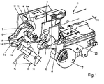
- Fig. 1 shows a breech block 2, with associated breech mechanism, disposed in the breech 1 of the weapon.
- the breech mechanism includes an operating shaft 3 which, at its first end, is provided with an operating arm 4. This latter cooperates with an operating cam 5 on a cam mounting 6. At its other end, the shaft is in cooperation with spring means 7.
- the shaft is provided with operating linkages 8 and the shaft is journalled in housings 9 and 10 in the breech 1.
- the mounting 6 for the operating cam is, at its first end, journalled in the casing 11 in a rotary journal which is symbolically intimated by reference numeral 12. At its other end, the operating cam mounting cooperates with a buffer device 13.
- the buffer device is journalled to the mounting 6 by the intermediary of a pivoting journal 14, and to the gear arc 15 of the gun by the intermediary of the pivot journal 16.
- a positionally fixing device for the mounting 6 of the operating cam is designated 17. This device 17 cooperates with the mounting 6 by the intermediary of a guiding surface 6a which, at the free end of the mounting 6, displays a chamfer 6b. Ejectors are designated 18.
- breech block 2 is illustrated in its closed position.
- a symbolically intimated round 19 is assumed to be rammed home and the rear edge of the round lies in engagement with the ejectors 18 in a per se known manner, such engagement having been dispensed with from the Drawings, for purposes of clarity.
- the breech recoils in relation to the operating cam mounting 6 and the buffer device 13.
- the cam 5 then causes a torque movement to be transmitted to the shaft 3 by the intermediary of the arm 4.
- This torque is effected against the action of the spring member 7 which, in the present case, consists of a helical spring which is placed under tension on the above-mentioned movement of the shaft.
- the torque on the shaft also occasions the operating linkages 8 to force the breech block downwardly towards its open position.
- the block mechanically acts upon the ejectors so that these are obliged to execute a pivotal movement about their journal 20 and thereby execute their ejection movement, during which the spent case in the barrel is withdrawn and ejected rearwardly.
- the mounting 6 is released from the device 17.
- the mounting 6 is thereby unrestrained to execute movements about its journal 12 against the action of the buffer device 13. Release of the mounting 6 may be effected approximately halfway along the travel of the recoil.
- the breech block In the fully recoiled position of the breech, the breech block is to turn and recuperate towards an arrest position according to Fig. 2.
- the arrest action is catered for by the above-mentioned ejectors which are allocated their arrest position according to Fig. 2 on ejection of the case of the most recently spent round.
- Each respective ejector 18 is provided with a shoulder 18a which is cooperative with a corresponding abutment surface 2a on the breech block.
- the spring member 7 thus holds the breech block 2 tensioned against the ejectors 18 during the recuperation movement of the breech.
- a new round 19' is rammed home, which may be effected because the breech block 2 assumes its arrested position.
- the ramming direction is indicated by the arrow 21.
- the ejectors In the arrest position according to Fig. 2, the ejectors are exposed to the rear edge 19" of the round 19'. A part of the kinetic energy inherent in the round 19' may thus be transmitted to the ejectors 18 which, in such an event, are entrained with the round so that the breech block is released. As soon as the breech block 2 is released, the spring member can actuate the breech block towards its closure position as shown in Fig. 1.
- the catch surfaces on the shoulders 2a and 18a may, in this instance, be provided with undercut surfaces which, in conjunction with the release of the case ejector from the breech block, occasion a downward movement of the breech block. This function provides for a predetermined retarda- tion/cushioning of the round 19'.
- Fig. 2a illustrates the release cycle between the case ejector 18 and the breech block 2.
- the downward movement of the breech block on the release action occasions impact against an abutment surface 18b which results in an upward movement of the breech block and aids in its upward movement, at the same time as contributing to the cushioning function on the impetus of the round.
- the wheel 4a of the arm 4 strikes against the guiding surface 6a. This impact is cushioned by the buffer device 13.
- the mounting 6- which in this position is freely suspended-is under the action of the spring member 7.
- the mounting 6 is urged upwardly at its end 6a by the arm 4.
- the breech block may already be actuated towards the arrest position mentioned above when the breech is in the initial phase of its recuperation movement from the fully recoiled position.
- the breech block will not be dependent on the configuration of the cam 5 and the position of the breech in its recuperation movement. This once again entails that the arrest cycle will be completed earlier and ramming of a new round can be commenced correspondingly earlier.
- the arm 4 acts against the operating cam at the end 6a of the mounting 6 against the action of the buffer device 13. This is preferably designed such that the abutment of the breech block against the ejectors 18 will be of optimum cycle as regards rapidity, jolts etc.
- Fig. 3 shows the end positions of the fixation device 17, the position corresponding to that of Fig. 1 being indicated by numeral 17' and the position corresponding to full recoil by numeral 17". It will be apparent to the skilled reader of this Drawing figure that release takes place once the breech has executed slightly more than half of its recoil movement.
- the shaft 14 On cushioning of the impact from the arm 4, the shaft 14 is to move to the position A, which, in the present case, corresponds to approximately 10 to 15 mm.
- Actuation from the arm 4 at the end 6a (see Fig. 1) entails a movement from the point A to the point B of approximately 25 mm.
- the end positions of the mounting 6 are indicated by 6' and 6".
- the buffer device In order to effectuate the first cushioning movement, the buffer device includes an annular spring 21 which gives a relatively slight cushioning movement and considerable energy absorption.
- the buffer device also includes hydraulic cushioning by means of the piston 22 in a liquid- filled cavity 23.
- the piston displays a non-return valve function, which entails that the piston arrangement does not cushion, or cushions to but a slight degree, the movement to point A, its action being substantially concentrated to cushioning the movement between point A and point B.
- cushioning or buffer arrangements are per se known in the Art and will not, therefore, be described in greater detail here.
- the buffer device includes an apparatus 24 which is provided with a piston plunger 25 which accommodates volume changes in the liquid (for example glycol) independently of temperature.
- spindle centre has been designated 26.
Landscapes
- Engineering & Computer Science (AREA)
- General Engineering & Computer Science (AREA)
- Portable Nailing Machines And Staplers (AREA)
- Toys (AREA)
- Vertical, Hearth, Or Arc Furnaces (AREA)
- Fire Alarms (AREA)
- Control Of Non-Electrical Variables (AREA)
Claims (5)
Priority Applications (1)
| Application Number | Priority Date | Filing Date | Title |
|---|---|---|---|
| AT86105168T ATE45032T1 (de) | 1985-04-26 | 1986-04-15 | Vorrichtung zur erhoehung der feuerrate fuer automatische waffen. |
Applications Claiming Priority (2)
| Application Number | Priority Date | Filing Date | Title |
|---|---|---|---|
| SE8502020 | 1985-04-26 | ||
| SE8502020A SE447759B (sv) | 1985-04-26 | 1985-04-26 | Anordning att hoja skotthastigheten i automatvapen |
Publications (2)
| Publication Number | Publication Date |
|---|---|
| EP0199259A1 EP0199259A1 (de) | 1986-10-29 |
| EP0199259B1 true EP0199259B1 (de) | 1989-07-26 |
Family
ID=20359979
Family Applications (1)
| Application Number | Title | Priority Date | Filing Date |
|---|---|---|---|
| EP86105168A Expired EP0199259B1 (de) | 1985-04-26 | 1986-04-15 | Vorrichtung zur Erhöhung der Feuerrate für automatische Waffen |
Country Status (6)
| Country | Link |
|---|---|
| US (1) | US4730539A (de) |
| EP (1) | EP0199259B1 (de) |
| AT (1) | ATE45032T1 (de) |
| CA (1) | CA1270401A (de) |
| DE (1) | DE3664683D1 (de) |
| SE (1) | SE447759B (de) |
Families Citing this family (1)
| Publication number | Priority date | Publication date | Assignee | Title |
|---|---|---|---|---|
| SE8901626L (sv) * | 1989-05-09 | 1990-11-10 | Bofors Ab | Anordning foer att vid ett grovkalibrigt eldvapen styra roerelsefoerloppet dels foer en ammunitionsenhet under dennas ansaettning i eldvapnet, dels foer ammunitionsenhetens hylsa vid eldvapnets avfyrning |
Family Cites Families (6)
| Publication number | Priority date | Publication date | Assignee | Title |
|---|---|---|---|---|
| NL35583C (de) * | 1928-07-23 | |||
| US1805601A (en) * | 1930-10-14 | 1931-05-19 | Charles L Ross | Firearms |
| US2613576A (en) * | 1944-11-30 | 1952-10-14 | United Shoe Machinery Corp | Wear plate for the breech mechanism of guns |
| NL72471C (de) * | 1945-04-21 | |||
| GB1255921A (en) * | 1965-05-07 | 1971-12-01 | Secr Defence | Improvements in or relating to breech mechanism |
| US3656400A (en) * | 1970-03-18 | 1972-04-18 | Oberlikon Buehrle Holding Ag | Automatic gun breech mechanism having latches to hold the breech block open |
-
1985
- 1985-04-26 SE SE8502020A patent/SE447759B/sv not_active IP Right Cessation
-
1986
- 1986-04-15 AT AT86105168T patent/ATE45032T1/de not_active IP Right Cessation
- 1986-04-15 EP EP86105168A patent/EP0199259B1/de not_active Expired
- 1986-04-15 DE DE8686105168T patent/DE3664683D1/de not_active Expired
- 1986-04-25 US US06/855,580 patent/US4730539A/en not_active Expired - Fee Related
- 1986-04-25 CA CA000507608A patent/CA1270401A/en not_active Expired
Also Published As
| Publication number | Publication date |
|---|---|
| CA1270401A (en) | 1990-06-19 |
| SE447759B (sv) | 1986-12-08 |
| ATE45032T1 (de) | 1989-08-15 |
| US4730539A (en) | 1988-03-15 |
| EP0199259A1 (de) | 1986-10-29 |
| SE8502020D0 (sv) | 1985-04-26 |
| DE3664683D1 (en) | 1989-08-31 |
| SE8502020L (sv) | 1986-10-27 |
Similar Documents
| Publication | Publication Date | Title |
|---|---|---|
| US7997183B2 (en) | Firearm with enhanced recoil and control characteristics | |
| JP3143544B2 (ja) | 火器の可動部のはね返りを減速する装置 | |
| US20140102287A1 (en) | Firearm with enhanced recoil and control characteristics | |
| NO325004B1 (no) | Rekylstyringsmekanisme for et vapen samt vapen for avfyring av et prosjektil | |
| WO1995016178A1 (en) | A firearm locking mechanism | |
| US6112636A (en) | Gas-operated pistol | |
| JP4246185B2 (ja) | 多砲身小火器のロック装置 | |
| US2918847A (en) | Machine gun | |
| US4321764A (en) | Hammer actuator | |
| US4986162A (en) | Blocking device to interrupt movement of a wedge-type breechblock | |
| EP0199259B1 (de) | Vorrichtung zur Erhöhung der Feuerrate für automatische Waffen | |
| US4448109A (en) | Automatic or semi-automatic firearm | |
| RU2049977C1 (ru) | Самозарядный пистолет | |
| US4974356A (en) | High chamber pressure pistol | |
| CN103743291B (zh) | 通用气控枪机机构 | |
| US5177320A (en) | Staged gas system | |
| US3713241A (en) | Striker assembly for firearms | |
| US3333508A (en) | Closed breech gun utilizing a hollow bolt and a firing pin as a gas cylinder and a piston, respectively | |
| US3427925A (en) | Actuating device for automatic firearms | |
| RU2174663C1 (ru) | Пистолет-пулемет | |
| EP0203337B1 (de) | Patronenhülsenauswerfer für automatische Waffen | |
| SE8901626D0 (sv) | Eldvapen | |
| KR102730919B1 (ko) | 리볼버형 최루탄 발사기용 탄창 스토퍼 장치 | |
| US2798415A (en) | Breechbolt lock for automatic firearms | |
| GB2248916A (en) | Self-loading hand weapon |
Legal Events
| Date | Code | Title | Description |
|---|---|---|---|
| PUAI | Public reference made under article 153(3) epc to a published international application that has entered the european phase |
Free format text: ORIGINAL CODE: 0009012 |
|
| AK | Designated contracting states |
Kind code of ref document: A1 Designated state(s): AT BE CH DE FR GB IT LI NL |
|
| 17P | Request for examination filed |
Effective date: 19870205 |
|
| 17Q | First examination report despatched |
Effective date: 19871120 |
|
| ITF | It: translation for a ep patent filed | ||
| GRAA | (expected) grant |
Free format text: ORIGINAL CODE: 0009210 |
|
| AK | Designated contracting states |
Kind code of ref document: B1 Designated state(s): AT BE CH DE FR GB IT LI NL |
|
| REF | Corresponds to: |
Ref document number: 45032 Country of ref document: AT Date of ref document: 19890815 Kind code of ref document: T |
|
| ET | Fr: translation filed | ||
| REF | Corresponds to: |
Ref document number: 3664683 Country of ref document: DE Date of ref document: 19890831 |
|
| PLBE | No opposition filed within time limit |
Free format text: ORIGINAL CODE: 0009261 |
|
| STAA | Information on the status of an ep patent application or granted ep patent |
Free format text: STATUS: NO OPPOSITION FILED WITHIN TIME LIMIT |
|
| 26N | No opposition filed | ||
| ITTA | It: last paid annual fee | ||
| PGFP | Annual fee paid to national office [announced via postgrant information from national office to epo] |
Ref country code: GB Payment date: 19930322 Year of fee payment: 8 |
|
| PGFP | Annual fee paid to national office [announced via postgrant information from national office to epo] |
Ref country code: FR Payment date: 19930417 Year of fee payment: 8 |
|
| PGFP | Annual fee paid to national office [announced via postgrant information from national office to epo] |
Ref country code: AT Payment date: 19930422 Year of fee payment: 8 |
|
| PGFP | Annual fee paid to national office [announced via postgrant information from national office to epo] |
Ref country code: NL Payment date: 19930430 Year of fee payment: 8 |
|
| PGFP | Annual fee paid to national office [announced via postgrant information from national office to epo] |
Ref country code: BE Payment date: 19930504 Year of fee payment: 8 |
|
| PGFP | Annual fee paid to national office [announced via postgrant information from national office to epo] |
Ref country code: CH Payment date: 19930519 Year of fee payment: 8 |
|
| PGFP | Annual fee paid to national office [announced via postgrant information from national office to epo] |
Ref country code: DE Payment date: 19930623 Year of fee payment: 8 |
|
| PG25 | Lapsed in a contracting state [announced via postgrant information from national office to epo] |
Ref country code: GB Effective date: 19940415 Ref country code: AT Effective date: 19940415 |
|
| PG25 | Lapsed in a contracting state [announced via postgrant information from national office to epo] |
Ref country code: LI Effective date: 19940430 Ref country code: CH Effective date: 19940430 Ref country code: BE Effective date: 19940430 |
|
| BERE | Be: lapsed |
Owner name: BOFORS A.B. Effective date: 19940430 |
|
| PG25 | Lapsed in a contracting state [announced via postgrant information from national office to epo] |
Ref country code: NL Effective date: 19941101 |
|
| GBPC | Gb: european patent ceased through non-payment of renewal fee |
Effective date: 19940415 |
|
| NLV4 | Nl: lapsed or anulled due to non-payment of the annual fee | ||
| PG25 | Lapsed in a contracting state [announced via postgrant information from national office to epo] |
Ref country code: FR Effective date: 19941229 |
|
| REG | Reference to a national code |
Ref country code: CH Ref legal event code: PL |
|
| PG25 | Lapsed in a contracting state [announced via postgrant information from national office to epo] |
Ref country code: DE Effective date: 19950103 |
|
| REG | Reference to a national code |
Ref country code: FR Ref legal event code: ST |
|
| PG25 | Lapsed in a contracting state [announced via postgrant information from national office to epo] |
Ref country code: IT Free format text: LAPSE BECAUSE OF NON-PAYMENT OF DUE FEES Effective date: 20050415 |