EP0199130B1 - Device for placing a presser foot in an automatic sewing machine - Google Patents
Device for placing a presser foot in an automatic sewing machine Download PDFInfo
- Publication number
- EP0199130B1 EP0199130B1 EP86104105A EP86104105A EP0199130B1 EP 0199130 B1 EP0199130 B1 EP 0199130B1 EP 86104105 A EP86104105 A EP 86104105A EP 86104105 A EP86104105 A EP 86104105A EP 0199130 B1 EP0199130 B1 EP 0199130B1
- Authority
- EP
- European Patent Office
- Prior art keywords
- presser foot
- placing
- sewing machine
- pair
- hook
- Prior art date
- Legal status (The legal status is an assumption and is not a legal conclusion. Google has not performed a legal analysis and makes no representation as to the accuracy of the status listed.)
- Expired
Links
Images


Classifications
-
- D—TEXTILES; PAPER
- D05—SEWING; EMBROIDERING; TUFTING
- D05B—SEWING
- D05B3/00—Sewing apparatus or machines with mechanism for lateral movement of the needle or the work or both for making ornamental pattern seams, for sewing buttonholes, for reinforcing openings or for fastening articles, e.g. buttons, by sewing
- D05B3/02—Sewing apparatus or machines with mechanism for lateral movement of the needle or the work or both for making ornamental pattern seams, for sewing buttonholes, for reinforcing openings or for fastening articles, e.g. buttons, by sewing with mechanisms for needle-bar movement
-
- Y—GENERAL TAGGING OF NEW TECHNOLOGICAL DEVELOPMENTS; GENERAL TAGGING OF CROSS-SECTIONAL TECHNOLOGIES SPANNING OVER SEVERAL SECTIONS OF THE IPC; TECHNICAL SUBJECTS COVERED BY FORMER USPC CROSS-REFERENCE ART COLLECTIONS [XRACs] AND DIGESTS
- Y10—TECHNICAL SUBJECTS COVERED BY FORMER USPC
- Y10T—TECHNICAL SUBJECTS COVERED BY FORMER US CLASSIFICATION
- Y10T29/00—Metal working
- Y10T29/51—Plural diverse manufacturing apparatus including means for metal shaping or assembling
- Y10T29/5191—Assembly
Definitions
- This invention relates to a device for placing a presser foot applied on a tailoring fabric. Particularly, this invention relates to a device for placing a presser foot applied on a patch cloth to be hem- sewn with an underlying base fabric.
- Recent automatic sewing business requires performance of sewing with high efficiency which includes rationalization of preparatory time and also switching time to the next job.
- a presser foot has been manually set on the patch cloth with little problem, because recent presser foots are made of plastic and their lightweight obviates the use of much time for accurate orientation with manual operators.
- quick, easy placement and displacement work of the presser foot has been a problem to determine how efficiently the intended sewing job will be prepared or switched in a line flow system.
- This invention is mainly intended to solve problems in placement of the presser foot before start of the sewing and in displacement of the same after the sewing finishes.
- this invention offers a vertically displaceable device comprising means for pressing and hooking a presser foot on its top face, further means for release and unhook thereof.
- Fig. 1 shows a front drawing of an embodiment of this invention partly broken and partly abbreviated for simplicity sake while the embodied device is in engagement with a presser foot.
- Fig. 2 is a partial, excerpted drawing to show how the device is releasing the presser foot by unhooking action.
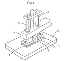
- Fig. 3 shows a perspective view of the device with some simplicity, but with complement to abbreviations in Fig. 1.
- the numeral 1 is a base plate equipped with hook means as well as other functional elements as will be noted below, and 1a is a beam, located above the base plate 1, where the plate 1 and the beam 1a are connected and adapted to displace or move up and down as one unit vertically along guide columns G, G (abbreviated in Fig. 1 and 2, but shown in Fig. 3) by some power source which is also abbreviated from drawings.
- l' is a block projected from the bottom face of the plate 1, and 2, 2 are hook arms pivoted at the side centers 2a, 2a of the plate 1 and urged by a spring 3, 3 respectively.
- the bottom tip of each arm 2 is curved inwardly to make a hook nail as numbered 2', 2".
- the numerals 11, 11 are screws to adjust the urging force by the springs 3, 3 respectively.
- the numeral 10 is a presser foot, normally molded of transparent acrylic resin, having a gross contour similar to a patch cloth, not shown, and further having a sectional shape like an inverse hollow plate with an edge foot 10a to touch on the patch cloth (not shown), block ports 10b to receive the blocks 1' (plurality of 10b may be recognized by Fig. 3) and hook ports 10d, 10d to receive hook nails 2', 2".
- the numeral 4 represents portions, located in Fig. 1 above the elements noted hereinbefore, but not limited as to configuration, to actuate hooking and unhooking actions in connection with placing and displacing actions of the device as a whole, where a pair of scissor arms 5, 5 (shown in Fig. 1 and 2, but abbreviated in Fig. 3) are arranged with their arm tips 5', 5' touched to the outer top tips of the arms 2, 2 and these arms 5, 5 are pivoted at 5a, 5a and at the shank ends, a pair of rollers 6, 6 are mounted with a small gap inbetween. This gap is bridged by a spring 7 to keep a certain gap length.
- the numeral 8 is an air cylinder, positioned between a pair of scissor arms 5, 5 to move a tapered piston head 9 which will wedge into a pair of rollers 6, 6.
- 12 is a stopper, extended from and secured around the fulcrum 5a, to control the wedging action noted above.
- the actuator means represented by the numeral 4 is connected with the hook means having the basic numerals 1 and 2, therefore it is understood that the elements represented by 4 as well as the elements represented by 1 and 2 are adapted to displace or move together as one unit.
- a pocket cloth is first set on a suit fabric where said presser foot 10 having a similar shape to the pocket cloth is next laid on the pocket cloth manually.
- the device comprising actuation means and hook means is operated to come down along the columns G, G as one unit consisting mainly of the base plate 1, the beam 1a, the scissor arms 5, the air cylinder 8 and the stopper 12.
- the downward move stops and the nails 2, 2 come into the hook ports 10d and catch the edges 10e as shown in Fig. 1, while the blocks 1' enter into the block ports 10b and the top face 10c of the presser foot 10 is pressed down. Consequently, the presser foot 10 is fixed in place and then the hem-sewing will take place.
- the air cylinder 8 is operated to push the piston head 9 into a pair of rollers 6, 6, by which the scissor arms 5, 5 make a close at their arm tips 5', 5' as shown in Fig. 2 and thereby the nails 2', 2' are opened or unfixed as also shown in Fig. 2. Then the device present above the pressor foot 10 starts to displace upward.
Landscapes
- Engineering & Computer Science (AREA)
- Textile Engineering (AREA)
- Sewing Machines And Sewing (AREA)
Description
- This invention relates to a device for placing a presser foot applied on a tailoring fabric. Particularly, this invention relates to a device for placing a presser foot applied on a patch cloth to be hem- sewn with an underlying base fabric.
- Recent automatic sewing business requires performance of sewing with high efficiency which includes rationalization of preparatory time and also switching time to the next job. Making reference to such a kind of problem as involved in an automatic pocket sewing machine where formation of a patch pocket is intended on a suit fabric by hem-sewing of a patch cloth, a presser foot has been manually set on the patch cloth with little problem, because recent presser foots are made of plastic and their lightweight obviates the use of much time for accurate orientation with manual operators. However, quick, easy placement and displacement work of the presser foot has been a problem to determine how efficiently the intended sewing job will be prepared or switched in a line flow system.
- This invention is mainly intended to solve problems in placement of the presser foot before start of the sewing and in displacement of the same after the sewing finishes. Specifically, this invention offers a vertically displaceable device comprising means for pressing and hooking a presser foot on its top face, further means for release and unhook thereof. Other objects as well as advantages attained by this invention will be apparent through descriptions hereinafter.
- Fig. 1 shows a front drawing of an embodiment of this invention partly broken and partly abbreviated for simplicity sake while the embodied device is in engagement with a presser foot. Fig. 2 is a partial, excerpted drawing to show how the device is releasing the presser foot by unhooking action. Fig. 3 shows a perspective view of the device with some simplicity, but with complement to abbreviations in Fig. 1. These drawings are presented by way of illustrating this invention. Therefore, these should not be construed as limiting the invention.
- This invention will be detailed hereinbelow with reference to a preferred embodiment shown in drawings. The
numeral 1 is a base plate equipped with hook means as well as other functional elements as will be noted below, and 1a is a beam, located above thebase plate 1, where theplate 1 and the beam 1a are connected and adapted to displace or move up and down as one unit vertically along guide columns G, G (abbreviated in Fig. 1 and 2, but shown in Fig. 3) by some power source which is also abbreviated from drawings. l' is a block projected from the bottom face of theplate side centers plate 1 and urged by aspring arm 2 is curved inwardly to make a hook nail as numbered 2', 2". Thenumerals springs - The
numeral 10 is a presser foot, normally molded of transparent acrylic resin, having a gross contour similar to a patch cloth, not shown, and further having a sectional shape like an inverse hollow plate with anedge foot 10a to touch on the patch cloth (not shown), block ports 10b to receive the blocks 1' (plurality of 10b may be recognized by Fig. 3) andhook ports hook nails 2', 2". - The
numeral 4 represents portions, located in Fig. 1 above the elements noted hereinbefore, but not limited as to configuration, to actuate hooking and unhooking actions in connection with placing and displacing actions of the device as a whole, where a pair ofscissor arms 5, 5 (shown in Fig. 1 and 2, but abbreviated in Fig. 3) are arranged with their arm tips 5', 5' touched to the outer top tips of thearms arms rollers spring 7 to keep a certain gap length. Thenumeral 8 is an air cylinder, positioned between a pair ofscissor arms tapered piston head 9 which will wedge into a pair ofrollers fulcrum 5a, to control the wedging action noted above. And the actuator means represented by thenumeral 4 is connected with the hook means having thebasic numerals - In operation, a pocket cloth is first set on a suit fabric where said presser
foot 10 having a similar shape to the pocket cloth is next laid on the pocket cloth manually. Then, the device comprising actuation means and hook means is operated to come down along the columns G, G as one unit consisting mainly of thebase plate 1, the beam 1a, thescissor arms 5, theair cylinder 8 and thestopper 12. At the point of touch down between nails 2', 2' of thehook arms top edge 10e of thepresser foot 10, the downward move stops and thenails hook ports 10d and catch theedges 10e as shown in Fig. 1, while the blocks 1' enter into the block ports 10b and thetop face 10c of thepresser foot 10 is pressed down. Consequently, thepresser foot 10 is fixed in place and then the hem-sewing will take place. - In the meantime of said sewing operation, it is recommended to prepare the next job on a side table, for instance, including setting of the other suit fabric whereon a pocket cloth and a presser foot are laid.
- When the outstanding hem-sewing finishes, the
air cylinder 8 is operated to push thepiston head 9 into a pair ofrollers scissor arms pressor foot 10 starts to displace upward. - As is seen from descriptions above, placement and displacement work for a presser foot are rationalized by this invention, whereby an idling time with operators will be saved. It is further understood by those skilled in the art that the foregoing description is directed to a preferred embodiment of the disclosed device and that various changes and modifications may be made in the invention without departing from the spirit and scope thereof.
Claims (2)
Applications Claiming Priority (2)
| Application Number | Priority Date | Filing Date | Title |
|---|---|---|---|
| JP60213/85 | 1985-03-25 | ||
| JP60060213A JPS61220693A (en) | 1985-03-25 | 1985-03-25 | Cloth presser attaching and detaching mechanism in automaticsewing machine |
Publications (2)
| Publication Number | Publication Date |
|---|---|
| EP0199130A1 EP0199130A1 (en) | 1986-10-29 |
| EP0199130B1 true EP0199130B1 (en) | 1988-11-17 |
Family
ID=13135648
Family Applications (1)
| Application Number | Title | Priority Date | Filing Date |
|---|---|---|---|
| EP86104105A Expired EP0199130B1 (en) | 1985-03-25 | 1986-03-25 | Device for placing a presser foot in an automatic sewing machine |
Country Status (4)
| Country | Link |
|---|---|
| US (1) | US4800829A (en) |
| EP (1) | EP0199130B1 (en) |
| JP (1) | JPS61220693A (en) |
| DE (1) | DE3661206D1 (en) |
Family Cites Families (14)
| Publication number | Priority date | Publication date | Assignee | Title |
|---|---|---|---|---|
| US2822094A (en) * | 1953-09-29 | 1958-02-04 | Greer Hydraulics Inc | Bridge manipulator |
| FR2215071A5 (en) * | 1973-01-22 | 1974-08-19 | Deltour Bernard | Drive arrangement for flat, e.g. textile sheet - comprises former held on sheet and moved by clamp mechanism |
| SU595145A1 (en) * | 1976-06-02 | 1978-02-28 | Предприятие П/Я А-7631 | Manipulator gripping head |
| CH615712A5 (en) * | 1977-11-25 | 1980-02-15 | Mefina Sa | |
| SU663577A1 (en) * | 1977-12-27 | 1979-05-25 | Предприятие П/Я М-5671 | Gripper |
| JPS5525841U (en) * | 1978-08-11 | 1980-02-19 | ||
| SU848353A1 (en) * | 1979-07-09 | 1981-07-23 | Краматорский Научно-Исследовательскийи Проектно-Технологический Институтмашиностроения | Industrial robot gripper |
| US4422393A (en) * | 1981-05-22 | 1983-12-27 | Usm Corporation | Sewing machine having automatic pallet handling |
| DE3201014C1 (en) * | 1982-01-15 | 1983-10-06 | Maschinenfabrik Carl Zangs Ag, 4150 Krefeld | Device for the releasable fastening of an embroidery frame to the frame guide of embroidering machines |
| IL66381A0 (en) * | 1982-07-23 | 1982-11-30 | Beta Eng & Dev Ltd | Automatic sewing apparatus |
| JPS6016375Y2 (en) * | 1982-08-23 | 1985-05-21 | 晃信精密機械株式会社 | Sewing machine presser foot connection device |
| JPS6072587A (en) * | 1983-09-27 | 1985-04-24 | 佐藤精器株式会社 | Method and apparatus for blind stitching of curved edge part |
| US4597714A (en) * | 1984-03-22 | 1986-07-01 | Thomson Components - Mostek Corporation | Robot gripper for integrated circuit leadframes |
| JPS6182791A (en) * | 1984-09-28 | 1986-04-26 | 三菱電機株式会社 | Holding apparatus |
-
1985
- 1985-03-25 JP JP60060213A patent/JPS61220693A/en active Granted
-
1986
- 1986-02-28 US US06/834,541 patent/US4800829A/en not_active Expired - Fee Related
- 1986-03-25 DE DE8686104105T patent/DE3661206D1/en not_active Expired
- 1986-03-25 EP EP86104105A patent/EP0199130B1/en not_active Expired
Also Published As
| Publication number | Publication date |
|---|---|
| DE3661206D1 (en) | 1988-12-22 |
| JPS6476B2 (en) | 1989-01-05 |
| EP0199130A1 (en) | 1986-10-29 |
| US4800829A (en) | 1989-01-31 |
| JPS61220693A (en) | 1986-09-30 |
Similar Documents
| Publication | Publication Date | Title |
|---|---|---|
| US4800829A (en) | Device for placing a presser foot in an automatic sewing machine | |
| US5170733A (en) | Trouser fly piece serging apparatus | |
| US4376504A (en) | Machine for attaching buttons having shanks to an article in a correctly buttoned condition | |
| US2697221A (en) | Fastener setting attachment | |
| JPH02255175A (en) | Sewing machine with device for moving piping piece having cut at center of both ends | |
| GB1309937A (en) | Apparatus for sewing patch pockets on to garments | |
| US4945843A (en) | Sewing machine workpiece alignment device | |
| US3789782A (en) | Sewing machine cutter | |
| CN223365061U (en) | Automatic positioning device for quick button and quick button binding machine | |
| JPH0243345Y2 (en) | ||
| EP0172630A1 (en) | Sewing machine attachment | |
| US2562398A (en) | Fabric shaping and pressing machine | |
| CN220376906U (en) | Sewing machine clamp | |
| CN207186038U (en) | One kind paving scalds machine | |
| KR900009017Y1 (en) | Machine for setting eylets | |
| CN215668473U (en) | Ribbon stripping and edging device of five-thread overedger | |
| JPS5920220Y2 (en) | Cross guide for cloth placement in automatic sewing machines | |
| JPH0217563Y2 (en) | ||
| CN222524872U (en) | Multifunctional cloth stitching device | |
| JPS5836388Y2 (en) | sewing machine presser foot | |
| US4406725A (en) | Fastener bonding machine | |
| JP2762731B2 (en) | Tape sewing machine | |
| CA1254370A (en) | Apparatus for assembling a pair of fastener elements | |
| US4883010A (en) | Thread chain cutting device | |
| KR940007643Y1 (en) | Work-feeding device |
Legal Events
| Date | Code | Title | Description |
|---|---|---|---|
| PUAI | Public reference made under article 153(3) epc to a published international application that has entered the european phase |
Free format text: ORIGINAL CODE: 0009012 |
|
| AK | Designated contracting states |
Kind code of ref document: A1 Designated state(s): DE FR GB IT |
|
| 17P | Request for examination filed |
Effective date: 19861107 |
|
| 17Q | First examination report despatched |
Effective date: 19880217 |
|
| RAP1 | Party data changed (applicant data changed or rights of an application transferred) |
Owner name: SATOH SEIKI CO., LTD. |
|
| GRAA | (expected) grant |
Free format text: ORIGINAL CODE: 0009210 |
|
| AK | Designated contracting states |
Kind code of ref document: B1 Designated state(s): DE FR GB IT |
|
| PG25 | Lapsed in a contracting state [announced via postgrant information from national office to epo] |
Ref country code: FR Free format text: THE PATENT HAS BEEN ANNULLED BY A DECISION OF A NATIONAL AUTHORITY Effective date: 19881117 |
|
| ITF | It: translation for a ep patent filed | ||
| REF | Corresponds to: |
Ref document number: 3661206 Country of ref document: DE Date of ref document: 19881222 |
|
| EN | Fr: translation not filed | ||
| PLBE | No opposition filed within time limit |
Free format text: ORIGINAL CODE: 0009261 |
|
| STAA | Information on the status of an ep patent application or granted ep patent |
Free format text: STATUS: NO OPPOSITION FILED WITHIN TIME LIMIT |
|
| 26N | No opposition filed | ||
| PGFP | Annual fee paid to national office [announced via postgrant information from national office to epo] |
Ref country code: GB Payment date: 19910314 Year of fee payment: 6 |
|
| ITTA | It: last paid annual fee | ||
| PGFP | Annual fee paid to national office [announced via postgrant information from national office to epo] |
Ref country code: DE Payment date: 19910531 Year of fee payment: 6 |
|
| PG25 | Lapsed in a contracting state [announced via postgrant information from national office to epo] |
Ref country code: GB Effective date: 19920325 |
|
| GBPC | Gb: european patent ceased through non-payment of renewal fee | ||
| PG25 | Lapsed in a contracting state [announced via postgrant information from national office to epo] |
Ref country code: DE Effective date: 19921201 |
|
| PG25 | Lapsed in a contracting state [announced via postgrant information from national office to epo] |
Ref country code: IT Free format text: LAPSE BECAUSE OF NON-PAYMENT OF DUE FEES;WARNING: LAPSES OF ITALIAN PATENTS WITH EFFECTIVE DATE BEFORE 2007 MAY HAVE OCCURRED AT ANY TIME BEFORE 2007. THE CORRECT EFFECTIVE DATE MAY BE DIFFERENT FROM THE ONE RECORDED. Effective date: 20050325 |