EP0198754A1 - Method of producing control matrices with diodes for an electro-optical flat vision screen, and flat screen produced by this method - Google Patents
Method of producing control matrices with diodes for an electro-optical flat vision screen, and flat screen produced by this method Download PDFInfo
- Publication number
- EP0198754A1 EP0198754A1 EP86400666A EP86400666A EP0198754A1 EP 0198754 A1 EP0198754 A1 EP 0198754A1 EP 86400666 A EP86400666 A EP 86400666A EP 86400666 A EP86400666 A EP 86400666A EP 0198754 A1 EP0198754 A1 EP 0198754A1
- Authority
- EP
- European Patent Office
- Prior art keywords
- phase
- layer
- conductive material
- semiconductor layer
- electrodes
- Prior art date
- Legal status (The legal status is an assumption and is not a legal conclusion. Google has not performed a legal analysis and makes no representation as to the accuracy of the status listed.)
- Granted
Links
Images


Classifications
-
- G—PHYSICS
- G02—OPTICS
- G02F—OPTICAL DEVICES OR ARRANGEMENTS FOR THE CONTROL OF LIGHT BY MODIFICATION OF THE OPTICAL PROPERTIES OF THE MEDIA OF THE ELEMENTS INVOLVED THEREIN; NON-LINEAR OPTICS; FREQUENCY-CHANGING OF LIGHT; OPTICAL LOGIC ELEMENTS; OPTICAL ANALOGUE/DIGITAL CONVERTERS
- G02F1/00—Devices or arrangements for the control of the intensity, colour, phase, polarisation or direction of light arriving from an independent light source, e.g. switching, gating or modulating; Non-linear optics
- G02F1/01—Devices or arrangements for the control of the intensity, colour, phase, polarisation or direction of light arriving from an independent light source, e.g. switching, gating or modulating; Non-linear optics for the control of the intensity, phase, polarisation or colour
- G02F1/13—Devices or arrangements for the control of the intensity, colour, phase, polarisation or direction of light arriving from an independent light source, e.g. switching, gating or modulating; Non-linear optics for the control of the intensity, phase, polarisation or colour based on liquid crystals, e.g. single liquid crystal display cells
- G02F1/133—Constructional arrangements; Operation of liquid crystal cells; Circuit arrangements
- G02F1/136—Liquid crystal cells structurally associated with a semi-conducting layer or substrate, e.g. cells forming part of an integrated circuit
- G02F1/1362—Active matrix addressed cells
- G02F1/1365—Active matrix addressed cells in which the switching element is a two-electrode device
-
- Y—GENERAL TAGGING OF NEW TECHNOLOGICAL DEVELOPMENTS; GENERAL TAGGING OF CROSS-SECTIONAL TECHNOLOGIES SPANNING OVER SEVERAL SECTIONS OF THE IPC; TECHNICAL SUBJECTS COVERED BY FORMER USPC CROSS-REFERENCE ART COLLECTIONS [XRACs] AND DIGESTS
- Y10—TECHNICAL SUBJECTS COVERED BY FORMER USPC
- Y10S—TECHNICAL SUBJECTS COVERED BY FORMER USPC CROSS-REFERENCE ART COLLECTIONS [XRACs] AND DIGESTS
- Y10S359/00—Optical: systems and elements
- Y10S359/90—Methods
Definitions
- the invention relates to a method for producing diode control matrices for an electrooptic flat display screen, in particular for a liquid crystal display screen, as well as a flat screen produced by this method.
- the general field of the invention is thin film electronics over a large area.
- the application targeted by the present invention is the integrated control of each elementary point of a liquid crystal screen.
- these screens generally comprise a large number of elementary points or picture elements of square or rectangular shape. These picture elements can be addressed individually. The definition of the screen depends on the number of points likely to receive information. Each point is controlled by applying an electric field. For the display of video information, matrix type displays have been provided. Each picture element is then defined by the intersection of two networks of orthogonal conductors called rows and columns.
- the performance of a matrix screen can be improved by mounting in series with the image element a nonlinear resistor which is practically insulating beyond a voltage threshold and which becomes more and more conductive beyond this threshold .
- Such a non-linear element can be made of varistor material as described in French patent application No. 81 16217 filed on August 25, 1981 in the name of the Applicant and published on March 4, 1983 under No. 2,512,240.
- liquid crystal display screens generally have defects in homogeneity of the contrast according to the picture elements, due to a dispersion of the characteristics of the switching elements which can be significant and which is difficult to eliminate - over large areas . These defects can also find their origin, to a lesser extent, in the thickness of the liquid crystal layer and in its bonding layer.
- non-linear dipole elements such as the structure based on two Schottky diodes produced in series and in opposition. These diodes are semiconductor diodes all having the same operating point in the characteristic current-voltage.
- French patent application No. 83 14542 filed on September 13, 1983 by the Applicant describes such devices produced in particular in the form of Schottky diodes.
- the method applies to non-linear elements such as Schottky diodes or head-to-tail PIN diodes produced on amorphous silicon.
- the invention also relates to a flat screen comprising a first blade and a second parallel blade between which an electro-optical material is placed, the faces of the two blades in contact with the electro-optical material being provided with electrodes and control conductors, the at least the first blade being transparent, characterized in that the electrodes of the second blade are coupled to the control conductors of the same blade by non-linear control elements produced according to the invention.
- a substrate plate 1 made of electrically insulating material which can be a transparent plate such as glass in the case of use in a liquid crystal display device by transparency.
- a uniform layer of a conductive and transparent material is deposited.
- This material can be a mixed tin and indium oxide (ITO) or an equivalent material (In20 ,, Sn0 2 ).
- ITO indium oxide
- Such a layer will have a thickness of between 500 and 1000 Angstroem. It is also possible to start from substrates covered with such a layer and available commercially. There is therefore, as shown in FIG. 1, a substrate plate 1 covered with a layer 2 of a transparent conductive material.
- a layer 3 of a metallic material such as platinum, molybdenum or palladium is deposited.
- This deposition is carried out by electron gun or by sputtering and leads to a layer of a few, hundreds of Angstroem in thickness.
- This metal layer will be used to form the grids of the Schottky diodes.
- FIG. 2 there is thus obtained a substrate 1 covered with a layer 2 of a transparent conductive material and with a metallic layer 3.
- electrodes such as E and column conductors such as C. are cut from the two layers 2 and 3 previously deposited. This cutting is carried out by a known photolithography process or by a plasma attack process. Each of these methods requires masking delimiting the contours of the areas not to be attacked. By this masking, the electrodes E have a shape adapted to the type of display to be produced. This is how this shape will usually be square or rectangular.
- the column conductors C are parallel ribbons interposed between columns of electrodes E.
- electrodes E are obtained comprising a layer 22 of transparent conductive material and a metallic layer 32 thus as conductors C comprising a layer 21 of transparent conductive material and a metallic layer 31.
- an undoped amorphous silicon layer referenced 4 in FIG. 4 is deposited.
- This deposition operation can use a plasma assisted deposition process at 250 degrees Celsius (Glow discharge in English terminology) or a vapor phase epitaxy process (CVD or Chemical Vapor Deposition in Anglo-Saxon teminology).
- CVD vapor phase epitaxy process
- the temperature can be gradually increased so as to obtain a decreasing profile of the incorporated hydrogen.
- Ori can also use a vapor phase epitaxy process under reduced pressure at around 550 degrees Celsius (LPCVD or Low Pressure Chemical Vapor Deposition).
- the thickness of the layer obtained must be from 2000 to 6000 Angstroem.
- a layer 5 of phosphorus doped amorphous silicon is deposited (n + type layer). This deposition is done by the same process as that used in the previous phase.
- the layer thickness should be 1000 to 2000 Angstroem. In the case where the process used is a vapor phase epitaxy at reduced pressure, it is necessary to provide for a posthydrogenation of the silicon layer before the deposition of the metal layer which will follow.
- a layer of metal 6 such as chromium or aluminum is deposited.
- the deposit is made by Joule effect.
- the amorphous silicon is photoconductive, the layer obtained must be approximately 500 Angstroms thick so as to act as a light screen for the layers of amorphous silicon.
- the mesa structures as shown in FIG. 5 are cut out from the layers of material 31, 32, 4, 5 and 6 and connecting the electrodes E to the conductor C. This cutting is done after masking of the surfaces corresponding to the mesa structures, either by chemical attack, or by plasma attack or any other method known in the art so as not to attack the tick 2 of transparent conductive material.
- each electrode E consisting of a zone 22 of transparent conductive material is coupled to conductor C also of transparent conductive material by two Schottky eri oppo diodes sition.
- the two diodes have a common metallic grid formed by the metallic layer 6. They are then made up of a layer 5 of n + doped silicon then of a layer 4 of undoped silicon and finally of a metallic layer 31, 32.
- the whole is annealed at a temperature between 250 and 280 degrees Celsius under vacuum or in an atmosphere of neutral gas.
- the purpose of this annealing is to improve the current-voltage characteristics of the Schottky diodes by forming a stable interface in platinum silicon.
- the metal layer 3 deposited during the second phase may not be attacked.
- the device can be used in reflection instead of being used in transparency. We can even then dispense with the deposition of transparent conductive material, which eliminates the first phase described above.
- the component thus produced is coupled to a plate 90 carrying, opposite the electrodes E, electrodes F.
- a space is provided between the electrodes E and F. This space is filled with 'an LC liquid crystal.
- a liquid crystal cell is thus produced, the control of which is carried out by a non-linear element constituted by Schottky diodes in opposition.
- nonlinear control elements consist of PIN type diodes, that is to say comprising successive semiconductor layers of p + doped, undoped and doped n +.
- a layer 2 of a conductive material is deposited on a substrate 1.
- This material can be transparent such as indium oxide (In 2 O 3 ) for operation in optical transmission. It can also be metal (such as chromium, nickel-chromium, aluminum) for operation in reflection.
- the layer thickness should be between 500 and 1000 Angstroem. The part shown in FIG. 7 is thus obtained.
- a layer 7 of p + doped silicon is deposited.
- This deposition can be done either by plasma assisted epitaxy (CVD) plasma assisted, or by reduced pressure vapor phase epitaxy (LPCVD).
- the thickness of this layer should be about 200 to 500 Angstroem thick.
- etching is carried out, by chemical etching in plasma for example, of the two layers 2 and 7 so as to produce electrodes E and column conductors C.
- This production therefore requires masking of the layers of materials 2 and 7 to be kept. A part is thus obtained as shown in FIG. 9.
- a layer 8 of undoped or lightly doped n-type amorphous silicon is deposited. This deposition is done by one of the methods described above.
- the layer thickness should be between 3000 and 5000 Angstroem.
- a layer 9 of n + type doped amorphous silicon of about 200 Angstroem thickness is deposited in the same way.
- a layer of metal 10 such as chromium, nickel-chromium or aluminum is deposited. This deposition is done by Joule effect and the thickness of the layer must be approximately 500 Angstroem to serve as a light screen for the previously deposited layers.
- the mesa structures are formed by chemical attack or plasma.
- the four layers 7, 8, 9 and 10 are attacked after having masked the parts to be preserved.
- FIG. 1-1 This gives a device as shown in Figure 1-1 in which -an electrode E- is coupled to a column conductor C by two diodes in opposition.
- the two diodes have in common a metal grid 10 and successively have a layer 9 of n + doped amorphous silicon, a layer 8 of undoped amorphous silicon, a layer 7 of p + doped amorphous silicon and a layer 2 of a conductive material .
- Such a diode control device can be used in a liquid crystal display cell as shown in FIG. 12 and constituted like the liquid crystal display cell in FIG. 6.
- the deposited silicon can be n + doped.
- the silicon instead of being doped n + , will be doped p +.
- a liquid crystal display device represented by FIG. 12 is obtained by associating, with the plate 1 (provided with the electrodes E, conductors C and control elements), a plate 90 provided with electrodes F and by filling the space existing between the two plates 1 and 90 with a liquid crystal LC.
- the screen technology itself is well known to those skilled in the art: anchoring layers, thickness controls, transparent counter electrodes and introduction of liquid crystal, etc.
- the process of the invention can be supplemented as shown in FIGS. 13 and 14 by a phase of passivation of the sides of the mesa structures obtained so as to eliminate the harmful leakage current which may appear on the vertical surfaces of the mesas.
- This passivation is done without additional masking step by depositing a dielectric on the whole of the blade 1, then anisotropic plasma attack (RIE) which preserves the dielectric only on the flanks of the mesas.
- RIE anisotropic plasma attack
- This passivation can also be done by depositing a dielectric followed by a photolithography which requires masking whose precision is not critical.
- the production method according to the invention is well suited to the production of redundant structures for example for the image element defined in two half-points, each half-point having access to the control diode, which minimizes the risk of bad diode operation.
- the method of the invention makes it possible to produce non-linear control elements of the diode type for a liquid crystal display screen.
- This method has the advantages described in the preamble to this description and in particular that of requiring only two masking operations which themselves do not require any particular precision.
Abstract
Procédé de réalisation de matrices de commande à diodes pour écran plat de visualisation électrooptique prévoyant de déposer sur un substrat (1) une couche de matériau conducteur (2) et de graver dans cette couche les électrodes (E) et les conducteurs de commande (C). L'ensemble est ensuite revêtu d'une couche semiconductrice amorphe non dopée (4), d'une couche semiconductrice amorphe dopée (5), d'une deuxième couche d'un matériau conducteur (6). Dans ces trois couches sont gravées des plots (ou éléments de commande) reliant les électrodes (E) aux conducteurs de commande (C). L'invention est applicable à la réalisation d'écrans de visualisation à cristal liquide.Method for producing diode control matrices for an electrooptic flat display screen providing for depositing on a substrate (1) a layer of conductive material (2) and etching in this layer the electrodes (E) and the control conductors (C ). The assembly is then coated with an undoped amorphous semiconductor layer (4), with a doped amorphous semiconductor layer (5), with a second layer of a conductive material (6). In these three layers are engraved studs (or control elements) connecting the electrodes (E) to the control conductors (C). The invention is applicable to the production of liquid crystal display screens.
Description
L'invention concerne un procédé de réalisation de matrices de commande à diodes pour écran plat de visualisation électrooptique notamment pour écran de visualisation à cristal liquide ainsi qu'un écran plat réalisé par ce procédé.The invention relates to a method for producing diode control matrices for an electrooptic flat display screen, in particular for a liquid crystal display screen, as well as a flat screen produced by this method.
Le domaine général de l'invention est l'électronique en couche mince sur grande surface. L'application visée par la présente invention est la commande intégrée de chaque point élémentaire d'un écran à cristal liquide.The general field of the invention is thin film electronics over a large area. The application targeted by the present invention is the integrated control of each elementary point of a liquid crystal screen.
Comme il est connu, ces écrans comportent généralement un grand nombre de points élémentaires ou éléments d'image de forme carrée ou rectangulaire.. Ces éléments d'image peuvent être adressés individuellement. La définition de l'écran est fonction du nombre de points susceptibles de recevoir une information. La commande de chaque point se fait par application d'un champ électrique. Pour la visualisation d'information vidéo, il a été prôposé des affichages de type matriciel. Chaque élément d'image est alors défini par l'intersection de deux réseaux de conducteurs orthogonaux appelés lignes et colonnes.As is known, these screens generally comprise a large number of elementary points or picture elements of square or rectangular shape. These picture elements can be addressed individually. The definition of the screen depends on the number of points likely to receive information. Each point is controlled by applying an electric field. For the display of video information, matrix type displays have been provided. Each picture element is then defined by the intersection of two networks of orthogonal conductors called rows and columns.
L'adressage d'un élément d'image au moyen de tensions de commande appliquées à la ligne et à la colonne qui le concement n'a pas besoin d'être maintenu si l'on adopte une technique de multiplexage temporel permettant par récurrence de rafraîchir l'état de l'écran. Cette-technique-se. fonde sur un effet de persistance qui peut être physiologique ou disponible au sein de l'élément de l'écran. Dans le cas de dispositifs d'affichage à cristaux. liquides, on peut assimiler un élément d'image à un condensateur dont la constante de temps est suffisante pour maintenir la charge entre deux adressages transitoires successifs.The addressing of a picture element by means of control voltages applied to the row and to the column which concent it does not need to be maintained if a time multiplexing technique is used which allows by recurrence refresh the screen state. This-technique. is based on a persistence effect which can be physiological or available within the screen element. In the case of crystal display devices. liquids, we can assimilate an image element to a capacitor whose time constant is sufficient to maintain the charge between two successive transient addresses.
Les performances d'un écran matriciel peuvent être améliorées en montant en série avec l'élément image une résistance non linéaire qui est pratiquement isolante au-delà d'un seuil de tension et qui devient de plus en plus conducteur au-delà de ce seuil.The performance of a matrix screen can be improved by mounting in series with the image element a nonlinear resistor which is practically insulating beyond a voltage threshold and which becomes more and more conductive beyond this threshold .
Un tel élément non linéaire peut être en matériau varistance comme cela est décrit dans la demande de brevet français N° 81 16217 déposée le 25 août 1981 au nom de la Demanderesse et publiée le 4 mars 1983 sous le N° 2 512 240.Such a non-linear element can be made of varistor material as described in French patent application No. 81 16217 filed on August 25, 1981 in the name of the Applicant and published on March 4, 1983 under No. 2,512,240.
Actuellement, les exigences de la technique en matière d'écrans de visualisation portent, en particulier, sur une meilleure définition de l'image. Dans le cas des écrans du type à affichage matriciel, on est alors amené à concevoir des dispositifs comportant un nombre élevé de lignes ou de colonnes d'adressage. Leur nombre peut aller jusqu'à 512 ou même 1024. Ceci augmente d'autant les éléments de commutation, donc le nombre de varistances dans la demande citée. Pour les fabrications en série, il est nécessaire notamment d'obtenir une bonne reproductivité et une grande stabilité de ces composants. Il est en outre nécessaire d'adapter, et ce également avec une bonne reproductibilité, la capacité électrique du composant à celle de la cellule associée. Or, les matériaux couramment utilisés, tels que des agglomérats de poudre d'oxyde de zinc, contenant des particules d'oxyde de bismuth et d'oxyde de manganèse ou autre matériau analogue, ne permettent pas de satisfaire entièrement ces exigences. La reproductibilité et la stabilité des varistances dépendent entre autre de la taille de grain et des techniques de passivation des joints de grains mis en oeuvre lors de la fabrication. La capacité parasite de la varistance liée également aux joints des grains est difficilement contrôlable.Currently, the technical requirements for display screens relate, in particular, to better definition of the image. In the case of screens of the matrix display type, it is then necessary to design devices comprising a high number of rows or addressing columns. Their number can go up to 512 or even 1024. This increases the switching elements correspondingly, therefore the number of varistors in the cited request. For mass production, it is necessary in particular to obtain good reproducibility and great stability of these components. It is also necessary to adapt, and this also with good reproducibility, the electrical capacity of the component to that of the associated cell. However, the materials commonly used, such as agglomerates of zinc oxide powder, containing particles of bismuth oxide and manganese oxide or other similar material, do not allow these requirements to be fully satisfied. The reproducibility and stability of the varistors depend, among other things, on the grain size and on the passivation techniques of the grain boundaries used during manufacture. The parasitic capacity of the varistor also linked to the grain boundaries is difficult to control.
D'autres éléments de commutation peuvent être utilisés. Néanmoins, les écrans de visualisation à cristal liquide présentent généralement des défauts d'homogénéité du contraste suivant les éléments d'image, dus à une dispersion des caractéristiques des éléments de commutation qui peut être importante et qui est difficile à éliminer -sur de grandes surfaces. Ces défauts peuvent également trouver leur origine, dans une moindre mesure, dans l'épaisseur de la couche de cristal liquide et dans sa couche d'accrochage.Other switching elements can be used. Nevertheless, liquid crystal display screens generally have defects in homogeneity of the contrast according to the picture elements, due to a dispersion of the characteristics of the switching elements which can be significant and which is difficult to eliminate - over large areas . These defects can also find their origin, to a lesser extent, in the thickness of the liquid crystal layer and in its bonding layer.
Afin de pallier ces inconvénients, on connaît des dispositifs dans lesquels les éléments non linéaires sont des transistors à films minces principalement à base de silicium amorphe ou de silicium polycristallin. Cependant ce type de technologie présente quelques difficultés qu'il faut résoudre pour obtenir un adressage de haute qualité:
- 1) meilleur contrôle des caractéristiques qui dépendent des propriétés de deux couches - (silicium et isolant) et de leur interface;
- 2) une technologie d'auto-alignement est nécessaire pour une meilleur reproductibilité sur grande surface.
- 1) better control of the characteristics which depend on the properties of two layers - (silicon and insulator) and their interface;
- 2) self-alignment technology is necessary for better reproducibility over a large area.
D'autres solutions prévoient que les éléments non linéaires dipolaires sont connues telle que la structure à base de deux diodes Schottky réalisée en série et en opposition. Ces diodes sont des diodes semiconductrices possédant tous le même moint de fonctionnement dans la caractéristique courant-tension. La demande de brevet français N° 83 14542 déposée le 13 septembre 1983 par la Demanderesse décrit de tels dispositifs réalisés notamment sous forme de diodes Schottky.Other solutions provide that the non-linear dipole elements are known such as the structure based on two Schottky diodes produced in series and in opposition. These diodes are semiconductor diodes all having the same operating point in the characteristic current-voltage. French patent application No. 83 14542 filed on September 13, 1983 by the Applicant describes such devices produced in particular in the form of Schottky diodes.
Cependant, la mise en oeuvre de cette solution présente quelques contraintes :
- -la fabrication comporte quatre niveaux de masquage ;
- -un isolement des flancs de la mésa a-Si est nécessaire entraînant un dépôt d'isolant à basse température (diélectrique, polyimide) qui, d'une part doit être de bonne qualité et d'autre part doit recouvrir entièrement le flanc ;
- -Les prises de contact métallique oxyde d'indium et d'étain (ou ITO) sur les métaux de grille Schottky sont nécessaires pour la connexion entre ces grilles, les colonnes et les électrodes points ;
- -Bien que peu élevés les multiniveaux existent - (principalement hauteur de la mésa) et il y a risque de coupure des colonnes et des connexions aux électrodes;
- -Les électrodes en oxyde d'Indium et d'étain (ITO) élaborées au dernier stade du procédé ne peuvent être recuites (pour les rendre conductrices) qu'à des températures compatibles avec la non-exodif- fusion de l'hydrogène contenu dans le silicium amorphe. La limite de 250-280°C est en général insuffisante pour un bon recuit de l'ITO.
- -the manufacturing includes four masking levels;
- -an isolation of the flanks of the mesa a-Si is necessary resulting in the deposition of insulator at low temperature (dielectric, polyimide) which, on the one hand must be of good quality and on the other hand must completely cover the flank;
- -The indium tin oxide (or ITO) metallic contact points on the Schottky grid metals are necessary for the connection between these grids, the columns and the point electrodes;
- -Although low multilevel exist - (mainly height of the mesa) and there is a risk of cutting the columns and connections to the electrodes;
- -Indium and tin oxide electrodes (ITO) developed at the last stage of the process can only be annealed (to make them conductive) at temperatures compatible with the non-exodif- fusion of the hydrogen contained in amorphous silicon. The limit of 250-280 ° C is generally insufficient for good annealing of the ITO.
La présente invention élimine ces différentes contraintes. En effet :
- -le procédé de fabrication de l'invention ne nécessite que deux niveaux de masquage et le positionnement des masques ne demande pas une grande précision;
- -l'isolement des flancs par un diélectrique n'est pas nécessaire pour les connexions;
- -il n'est pas nécessaire de prise de contact par réservation;
- -les électrodes et colonnes conductrices sont parfaitement coplanaires;
- -il n'y a pas de limite pour le recuit de l'ITO (ou autres semi-transparents genre In203) si ce n'est la compatibilité avec le substrat utilisé.
- the manufacturing process of the invention requires only two masking levels and the positioning of the masks does not require great precision;
- -insulation of the sides by a dielectric is not necessary for connections;
- -It is not necessary to make contact by reservation;
- -the electrodes and conductive columns are perfectly coplanar;
- -There is no limit for the annealing of ITO (or other semi-transparent In 2 0 3 type ) other than compatibility with the substrate used.
Le procédé s'applique à des éléments non linéaires types diodes Schottky ou diodes PIN tête- bêche élaborées sur du silicium amorphe.The method applies to non-linear elements such as Schottky diodes or head-to-tail PIN diodes produced on amorphous silicon.
L'invention concerne donc un procédé de réalisation de matrices de commande à diodes pour écran plat de visualisation électrooptique comportant un substrat muni d'une face plane, caractérisé en ce qu'il comporte les phases suivantes:
- -phase de dépôt sur la surface de la face plane du substrat d'une première couche d'un matériau conducteur;
- -phase d'attaque de la couche de matériau conducteur pour former les électrodes de commande de l'écran de visualisation et les conducteurs de commande;
- -phase de dépôt d'une couche semiconductrice amorphe non dopée;
- -phase de dépôt d'une couche semiconductrice amorphe dopée ;
- -phase de dépôt d'une deuxième couche d'un matériau conducteur ;
- -phase d'attaque des différentes couches ainsi déposées jusqu'à la première couche de matériau conducteur de façon à créer des plots reliant les conducteurs de commande aux électrodes de commande.
- -phase of deposition on the surface of the flat face of the substrate of a first layer of a conductive material;
- attack phase of the layer of conductive material to form the display screen control electrodes and the control conductors;
- -phase of deposition of an undoped amorphous semiconductor layer;
- -phase of deposition of a doped amorphous semiconductor layer;
- -phase of depositing a second layer of a conductive material;
- -attack phase of the different layers thus deposited up to the first layer of conductive material so as to create pads connecting the control conductors to the control electrodes.
L'invention concerne également un écran plat comportant une première -lame-et une deuxlème lame parallèles entre lesquelles est placé un matériau électrooptique, les faces des deux lames en contact avec le matériau électrooptique étant munies d'électrodes et de conducteurs de commande, la première lame au moins étant transparente, caractérisé en ce que les électrodes de la deuxième lame sont couplées aux conducteurs de commande de la même lame par des éléments de commande non linéaires réalisés selon l'invention.The invention also relates to a flat screen comprising a first blade and a second parallel blade between which an electro-optical material is placed, the faces of the two blades in contact with the electro-optical material being provided with electrodes and control conductors, the at least the first blade being transparent, characterized in that the electrodes of the second blade are coupled to the control conductors of the same blade by non-linear control elements produced according to the invention.
Les différents objets et caractéristiques de l'invention seront détaillés et dans la description qui va suivre faite en se reportant aux figures annexées qui représentent:
- -les figures 1 à 6, un exemple de réalisation du procédé de l'invention selon lequel les éléments non linéaires sont des diodes Schottky;
- -les figures 7 à 12, une variante du procédé de l'invention selon lequel les éléments non linéaires sont des diodes PIN ;
- -les figures 13 et 14, la passivation des flancs des éléments linéaires de l'invention.
- FIGS. 1 to 6, an exemplary embodiment of the method of the invention according to which the non-linear elements are Schottky diodes;
- FIGS. 7 to 12, a variant of the method of the invention according to which the non-linear elements are PIN diodes;
- FIGS. 13 and 14, the passivation of the sides of the linear elements of the invention.
En se reportant aux figures 1 à 6, on va tout d'abord décrire un exemple de réalisation du procédé de l'invention permettant de réaliser des diodes Schottky sur un substrat en vue de commander un dispositif d'affichage à cristal liquide.Referring to Figures 1 to 6, we will first describe an embodiment of the method of the invention for producing Schottky diodes on a substrate in order to control a liquid crystal display device.
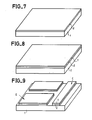
On dispose d'une plaque de substrat 1 en matériau isolant électriquement qui peut être une plaque transparente telle que du verre dans le cas d'une utilisation dans un dispositif d'affichage à cristal liquide par transparence.There is a
Au cours d'une première phase, on dépose une couche uniforme d'un matériau conducteur et transparent. Ce matériau peut être un oxyde mixte d'étain et d'indium (ITO) ou un matériau équivalent (In20,, Sn02). Une telle couche aura une épaisseur comprise entre 500 et 1000 Angstroem. On peut aussi partir de substrats recouverts d'une telle couche et disponibles dans le commerce. On a donc, comme représenté en figure 1, une plaque de substrat 1 recouvert d'une couche 2 d'un matériau conducteur transparent.During a first phase, a uniform layer of a conductive and transparent material is deposited. This material can be a mixed tin and indium oxide (ITO) or an equivalent material (In20 ,, Sn0 2 ). Such a layer will have a thickness of between 500 and 1000 Angstroem. It is also possible to start from substrates covered with such a layer and available commercially. There is therefore, as shown in FIG. 1, a
Au cours d'une deuxième phase, on dépose une couche 3 d'un matériau métallique tel que du platine, du molybdène ou du palladium. Ce dépôt se fait par canon à électrons ou par pulvérisation cathodique et conduit à obtenir une couche de quelques,centaines d'Angstroem d'épaisseur. Cette couche métallique servira à constituer les grilles des diodes Schottky. On obtient ainsi comme représenté en figure 2, un substrat 1 recouvert d'une couche 2 d'un matériau conducteur transparent et d'une couche métallique 3.During a second phase, a layer 3 of a metallic material such as platinum, molybdenum or palladium is deposited. This deposition is carried out by electron gun or by sputtering and leads to a layer of a few, hundreds of Angstroem in thickness. This metal layer will be used to form the grids of the Schottky diodes. As shown in FIG. 2, there is thus obtained a
Au cours d'une troisième phase telle que représentée en figure 3, on découpe dans les deux couches 2 et 3 déposées précédemment, des électrodes telle que E et des conducteurs de colonne tel que C. Cette découpe se fait par un procédé connu de photolithographie ou par un procédé d'attaque au plasma. Chacune de ces méthodes nécessite un masquage délimitant les contours des zones à ne pas attaquer. Par ce masquage, les électrodes E ont une forme adaptée au type d'affichage à réaliser. C'est ainsi que couramment cette forme sera carrée ou rectangulaire.During a third phase as shown in FIG. 3, electrodes such as E and column conductors such as C. are cut from the two
Les conducteurs de colonne C sont des rubans parallèles intercalés entre des colonnes d'électrodes E. On obtient ainsi, comme représenté en figure 3, sur un substrat 1, des électrodes E comportant une couche 22 de matériau conducteur transparent et une couche métallique 32 ainsi que des conducteurs C comportant une couche 21 de matériau conducteur transparent et une couche métallique 31.The column conductors C are parallel ribbons interposed between columns of electrodes E. Thus, as shown in FIG. 3, on a
Au cours d'une quatrième phase, on dépose une couche de silicium amorphe non dopée référencée 4 sur la figure 4. Cette opération de dépôt peut utiliser un procédé de dépôt assisté par plasma à 250 degrés Celsius (Glow discharge in terminologie anglo-saxonne) ou un procédé d'épitaxie en phase vapeur (CVD ou Chemical Vapor Deposition en teminologie anglo-saxonne). Au cours du dépôt du silicium amorphe non dopé, on peut augmenter progressivement la température de façon à obtenir un profil décroissant de l'hydrogène incorporé. Ori peut également utiliser un procédé d'épitaxie en phase vapeur sous pression réduite à environ 550 degrés Celsius (LPCVD ou Low Pressure Chemical Vapor Deposition). L'épaisseur de la couche obtenue doit être de 2000 à 6000 Angstroem.During a fourth phase, an undoped amorphous silicon layer referenced 4 in FIG. 4 is deposited. This deposition operation can use a plasma assisted deposition process at 250 degrees Celsius (Glow discharge in English terminology) or a vapor phase epitaxy process (CVD or Chemical Vapor Deposition in Anglo-Saxon teminology). During the deposition of undoped amorphous silicon, the temperature can be gradually increased so as to obtain a decreasing profile of the incorporated hydrogen. Ori can also use a vapor phase epitaxy process under reduced pressure at around 550 degrees Celsius (LPCVD or Low Pressure Chemical Vapor Deposition). The thickness of the layer obtained must be from 2000 to 6000 Angstroem.
Au cours d'une cinquième phase, on dépose une couche 5 de silicium amorphe dopée au phosphore (couche de type n+). Ce dépôt se fait par le même procédé que celui utilisé dans la phase précédente. L'épaisseur de la couche doit être de 1000 à 2000 Angstroem. Dans le cas où le procédé utilisé est une épitaxie en phase vapeur à pression réduite, il est nécessaire de prévoir une posthydrogénation de la couche de silicium avant le dépôt de la couche de métal qui va suivre.During a fifth phase, a
En effet, au cours d'une sixième phase, on procède au dépôt d'une couche de métal 6 tel que du chrome ou de l'aluminium. Le dépôt se fait par effet Joule. Le silicium amorphe étant photo-conducteur, la couche obtenue doit avoir environ 500 Angstroem d'épaisseur de façon à servir d'écran à la lumière pour les couches de silicium amorphe.In fact, during a sixth phase, a layer of
A l'issue de la sixième phase, on obtient un composant tel que représenté en figure 4 avec les électrodes E et le conducteur de colonne C déposés sur le substrat 1, l'ensemble étant entièrement recouvert par les trois couches 4, 5 et 6 déposées successivement au cours des phases précédemment décrites.At the end of the sixth phase, a component is obtained as shown in FIG. 4 with the electrodes E and the column conductor C deposited on the
Au cours d'une septième phase on procède à la découpe dans les couches de matériau 31, 32, 4, 5 et 6 de structures mésas telles que représentées en figure 5 et reliant les électrodes E au conducteur C. Cette découpe se fait, après masquage des surfaces correspondant aux structures mésas, soit par attaque chimique, soit par attaque plasma ou tout autre procédé connu dans la technique de façon à ne pas attaquer la coche 2 de matériau conducteur transparent.During a seventh phase, the mesa structures as shown in FIG. 5 are cut out from the layers of
Comme cela est représenté en figure 5, chaque électrode E constituée d'une zone 22 en matériau conducteur transparent est couplée au conducteur C également en matériau conducteur transparent par deux diodes Schottky eri opposition. Les deux diodes ont une grille métallique commune constituée par la couche métallique 6. Elles sont ensuite constituées d'une couche 5 de silicium dopé n+ puis d'une couche 4 de silicium non dopé et enfin d'une couche métallique 31, 32.As shown in Figure 5, each electrode E consisting of a
Lors d'une huitième phase l'ensemble est recuit à une température comprise entre 250 et 280 degrés Celsius sous vide ou en atmosphère de gaz neutre. Ce recuit a pour objet d'améliorer les caractéristiques courant-tension des diodes Schottky par formation d'une interface stable en silicium de platine.During an eighth phase, the whole is annealed at a temperature between 250 and 280 degrees Celsius under vacuum or in an atmosphere of neutral gas. The purpose of this annealing is to improve the current-voltage characteristics of the Schottky diodes by forming a stable interface in platinum silicon.
Il est à noter que lors de la. septième phase précédente, la couche métallique 3 déposée lors de la deuxième phase, peut ne pas être attaquée. Dans ce cas, le dispositif pourra être utilisé en réflexion au lieu d'être utilisé en transparence. On peut même alors, se dispenser du dépôt de matériau conducteur transparent ce qui supprime la première phase décrite précédemment.It should be noted that during the. seventh previous phase, the metal layer 3 deposited during the second phase, may not be attacked. In this case, the device can be used in reflection instead of being used in transparency. We can even then dispense with the deposition of transparent conductive material, which eliminates the first phase described above.
Comme cela est représenté en figure 6, le composant ainsi réalisé est couplé à une plaque 90 portant, en vis-à-vis des électrodes E, des électrodes F. Un espace est prévu entre les électrodes E et F. Cet espace est rempli d'un cristal liquide LC. On réalise ainsi une cellule à cristal liquide dont la commande se fait par un élément non linéaire constitué par des diodes Schottky en opposition.As shown in FIG. 6, the component thus produced is coupled to a
En se reportant aux figures 7 à 12, on va maintenant décrire une variante du procédé de l'invention. Ce procédé vise à réaliser des' éléments de commande non linéaires constitués de diodes de type PIN, c'est-à-dire comportant des couches de semiconducteurs successives dopée p+, non dopée et dopée n+.Referring to Figures 7 to 12, we will now describe a variant of the method of the invention. This method aims to achieve nonlinear control elements consist of PIN type diodes, that is to say comprising successive semiconductor layers of p + doped, undoped and doped n +.
Selon une première phase, on dépose sur un substrat 1 une couche 2 d'un matériau conducteur. Ce matériau peut être transparent tel que de l'oxyde d'indium (In2O3) pour un fonctionnement en transmission optique. Il peut être également du métal (tel que du chrome, du Nickel-chrome, de l'aluminium) pour un fonctionnement en réflexion. L'épaisseur de la couche doit avoir entre 500 et 1000 Angstroem. On obtient ainsi la pièce représentée en figure 7.According to a first phase, a
Au cours d'une deuxième phase, on dépose une couche 7 de silicium dopée p+. Ce dépôt peut se faire soit par épitaxie en phase vapeur (CVD) assisté plasma, soit par épitaxie en phase vapeur à pression réduite (LPCVD). L'épaisseur de cette couche doit avoir environ 200 à 500 Angstroem d'épaisseur.During a second phase, a
Au cours d'une troisième phase, on procède à une gravure, par attaque chimique en plasma par exemple, des deux couches 2 et 7 de façon à réaliser des électrodes E et des conducteurs de colonnes C. Cette réalisation nécessite donc un masquage des couches de matériaux 2 et 7 à conserver. On obtient ainsi une pièce telle que représentée en figure 9.During a third phase, etching is carried out, by chemical etching in plasma for example, of the two
Au cours d'une quatrième phase, on dépose une couche 8 de silicium amorphe non dopé ou légèrement dopé de type n. Ce dépôt se fait par l'une des méthodes décrites précédemment. L'épaisseur de la couche doit avoir entre 3000 et 5000 Angstroem.During a fourth phase, a
Au cours d'une cinquième phase, on-déposer de la même façon une couche 9 de silicium amorphe dopé de type n+ et d'épaisseur 200 Angstroem environ.During a fifth phase, a layer 9 of n + type doped amorphous silicon of about 200 Angstroem thickness is deposited in the same way.
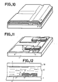
Au cours d'une sixième phase, on dépose une couche de métal 10 tel que du chrome, du Nickel-chrome ou de l'aluminium. Ce dépôt se fait par effet Joule et l'épaisseur de la couche doit être d'environ 500 Angstroem pour servir d'écran à la lumière pour les couches déposées précédemment.During a sixth phase, a layer of
Enfin, au cours d'une septième phase, on procède à la formation de structures mésas par attaque chimique ou plasma. Les quatre couches 7, 8, 9 et 10 sont attaquées après avoir masqué les parties à conserver.Finally, during a seventh phase, the mesa structures are formed by chemical attack or plasma. The four
On obtient ainsi un dispositif tel que représenté en figure 1-1 dans-lequel -une électrode E- est couplée à un conducteur de colonne C par deux diodes en opposition. Les deux diodes ont en commun une grille métallique 10 et possèdent successivement une couche 9 de silicium amorphe dopée n+, une couche 8 de silicium amorphe non dopée, une couche 7 de silicium amorphe dopée p+ et une couche 2 d'un matériau conducteur.This gives a device as shown in Figure 1-1 in which -an electrode E- is coupled to a column conductor C by two diodes in opposition. The two diodes have in common a
Un tel dispositif de commande à diodes peut être utilisé dans une cellule d'affichage à cristal liquide tel que représenté en figure 12 et constituée comme la cellule d'affichage à cristal liquide de la figure 6.Such a diode control device can be used in a liquid crystal display cell as shown in FIG. 12 and constituted like the liquid crystal display cell in FIG. 6.
Il est à noter que dans le procédé ainsi décrit, au cours de la deuxième phase, le silicium déposé peut être dopé n+. Dans ce cas, au cours de la cinquième phase, le silicium au lieu d'être dopé n+, sera dopé p+. On obtiendra alors des diodes inversées par rapport à celles représentées en figure 11.It should be noted that in the method thus described, during the second phase, the deposited silicon can be n + doped. In this case, during the fifth phase, the silicon, instead of being doped n + , will be doped p +. We will then obtain inverted diodes compared to those represented in FIG. 11.
De la même façon que cela a été décrit en se référant à la figure 6, on obtient un dispositif d'affichage à cristal liquide représenté par la figure 12 en associant, à la plaque 1 (muni des électrodes E, des conducteurs C et des éléments de commande), une plaque 90 munie d'électrodes F et en remplissant l'espace existant entre les deux plaques 1 et 90 par un cristal liquide LC.In the same way as has been described with reference to FIG. 6, a liquid crystal display device represented by FIG. 12 is obtained by associating, with the plate 1 (provided with the electrodes E, conductors C and control elements), a
La technologie de l'écran proprement dit est bien connue de l'homme de l'art : couches d'ancrage, commandes d'épaisseur, contre-électrodes transparentes et introduction du cristal liquide, etc...The screen technology itself is well known to those skilled in the art: anchoring layers, thickness controls, transparent counter electrodes and introduction of liquid crystal, etc.
Par ailleurs, le procédé de l'invention peut être complété comme cela est représenté en figures 13 et 14 par une phase de passivation des flancs des structures mésas obtenues de façon à éliminer les courant de fuites néfastes pouvant apparaître sur les surfaces verticales des mésas. Cette passivation se fait sans étape de masquage supplémentaire par dépôt d'un diélectrique sur l'ensemble de la lame 1, puis attaque plasma anisotrope (RIE) qui conserve le diélectrique uniquement sur les flancs des mésas.Furthermore, the process of the invention can be supplemented as shown in FIGS. 13 and 14 by a phase of passivation of the sides of the mesa structures obtained so as to eliminate the harmful leakage current which may appear on the vertical surfaces of the mesas. This passivation is done without additional masking step by depositing a dielectric on the whole of the
Cette passivation peut également se faire par dépôt d'un diélectrique suivi d'une photolithogravu- re qui nécessite un masquage dont la précision n'est pas critique.This passivation can also be done by depositing a dielectric followed by a photolithography which requires masking whose precision is not critical.
Le procédé de réalisation selon l'invention est bien adapté à la réalisation de structures redondantes par exemple pour l'élément image défini en deux demi-points, chaque demi-point ayant accès à la diode de commande, ce qui minimise le rique de mauvais fonctionnement de diode.The production method according to the invention is well suited to the production of redundant structures for example for the image element defined in two half-points, each half-point having access to the control diode, which minimizes the risk of bad diode operation.
On voit donc que le procédé de l'invention permet de réaliser des éléments de commande non linéaires de type diodes pour écran de visualisation à cristal liquide. Ce procédé présente les avantages décrits dans le préambule de la présente description et notamment celui de ne nécessiter que deux opérations de masquage qui ne nécessitent elles-mêmes aucune précision particulière.It can therefore be seen that the method of the invention makes it possible to produce non-linear control elements of the diode type for a liquid crystal display screen. This method has the advantages described in the preamble to this description and in particular that of requiring only two masking operations which themselves do not require any particular precision.
Claims (10)
Applications Claiming Priority (2)
| Application Number | Priority Date | Filing Date | Title |
|---|---|---|---|
| FR8505008A FR2579809B1 (en) | 1985-04-02 | 1985-04-02 | METHOD FOR PRODUCING DIE-CONTROLLED DIES FOR ELECTRO-OPTICAL DISPLAY FLAT SCREEN AND FLAT SCREEN PRODUCED BY THIS PROCESS |
| FR8505008 | 1985-04-02 |
Publications (2)
| Publication Number | Publication Date |
|---|---|
| EP0198754A1 true EP0198754A1 (en) | 1986-10-22 |
| EP0198754B1 EP0198754B1 (en) | 1989-12-06 |
Family
ID=9317865
Family Applications (1)
| Application Number | Title | Priority Date | Filing Date |
|---|---|---|---|
| EP86400666A Expired EP0198754B1 (en) | 1985-04-02 | 1986-03-27 | Method of producing control matrices with diodes for an electro-optical flat vision screen, and flat screen produced by this method |
Country Status (5)
| Country | Link |
|---|---|
| US (1) | US4653858A (en) |
| EP (1) | EP0198754B1 (en) |
| JP (1) | JPS61232662A (en) |
| DE (1) | DE3667340D1 (en) |
| FR (1) | FR2579809B1 (en) |
Cited By (2)
| Publication number | Priority date | Publication date | Assignee | Title |
|---|---|---|---|---|
| EP0513911A1 (en) * | 1991-05-17 | 1992-11-19 | Philips Electronics Uk Limited | Method of fabricating mim type device arrays and display devices incorporating such arrays |
| EP0521565A1 (en) * | 1991-07-04 | 1993-01-07 | Koninklijke Philips Electronics N.V. | Semiconductor device and method of manufacturing same, display device and support plate for same provided with such a semiconductor device |
Families Citing this family (22)
| Publication number | Priority date | Publication date | Assignee | Title |
|---|---|---|---|---|
| FR2579775B1 (en) * | 1985-04-02 | 1987-05-15 | Thomson Csf | METHOD FOR PRODUCING NON-LINEAR CONTROL ELEMENTS FOR FLAT SCREEN FOR ELECTRO-OPTICAL VISUALIZATION AND FLAT SCREEN PERFORMED ACCORDING TO THIS METHOD |
| FR2593631B1 (en) * | 1986-01-27 | 1989-02-17 | Maurice Francois | GRID RESISTANT ACTIVE MATRIX DISPLAY SCREEN AND METHODS OF MAKING SAME |
| US5042917A (en) * | 1986-04-25 | 1991-08-27 | Matsushita Electric Industrial Co., Ltd. | Liquid crystal matrix display unit |
| FR2621728B1 (en) * | 1987-10-09 | 1990-01-05 | Thomson Csf | SYSTEM FOR VIEWING HALF-TONE IMAGES ON A MATRIX SCREEN |
| JP2605382B2 (en) * | 1987-12-18 | 1997-04-30 | セイコーエプソン株式会社 | Active matrix substrate manufacturing method |
| FR2640809B1 (en) * | 1988-12-19 | 1993-10-22 | Chouan Yannick | PROCESS FOR ETCHING A METAL OXIDE LAYER AND SIMULTANEOUSLY DEPOSITING A POLYMER FILM, APPLICATION OF THIS PROCESS TO THE MANUFACTURE OF A TRANSISTOR |
| GB8902443D0 (en) * | 1989-02-03 | 1989-03-22 | Jones Barbara L | Radiation detector |
| US5084131A (en) * | 1990-01-11 | 1992-01-28 | Matsushita Electric Industrial Co., Ltd. | Fabrication method for thin film electroluminescent panels |
| GB2244860A (en) * | 1990-06-04 | 1991-12-11 | Philips Electronic Associated | Fabricating mim type device array and display devices incorporating such arrays |
| US5206749A (en) * | 1990-12-31 | 1993-04-27 | Kopin Corporation | Liquid crystal display having essentially single crystal transistors pixels and driving circuits |
| US5258320A (en) * | 1990-12-31 | 1993-11-02 | Kopin Corporation | Single crystal silicon arrayed devices for display panels |
| US5362671A (en) * | 1990-12-31 | 1994-11-08 | Kopin Corporation | Method of fabricating single crystal silicon arrayed devices for display panels |
| US5528397A (en) * | 1991-12-03 | 1996-06-18 | Kopin Corporation | Single crystal silicon transistors for display panels |
| FR2682798B1 (en) * | 1991-10-22 | 1994-01-21 | Sextant Avionique | METHOD AND DEVICE FOR OPTIMIZING THE PERFORMANCE OF A LIQUID CRYSTAL MATRIX SCREEN AS A FUNCTION OF THE ANGLE OF OBSERVATION. |
| FR2696258B1 (en) * | 1992-09-25 | 1994-10-28 | Sextant Avionique | Device for managing a human-machine interaction system. |
| US6040201A (en) | 1996-09-17 | 2000-03-21 | Citizen Watch Co., Ltd. | Method of manufacturing thin film diode |
| US5866301A (en) * | 1997-04-08 | 1999-02-02 | Citizen Watch Co., Ltd. | Method of manufacturing thin film diode |
| US6180444B1 (en) | 1998-02-18 | 2001-01-30 | International Business Machines Corporation | Semiconductor device having ultra-sharp P-N junction and method of manufacturing the same |
| FR2875947B1 (en) * | 2004-09-30 | 2007-09-07 | Tracit Technologies | NOVEL STRUCTURE FOR MICROELECTRONICS AND MICROSYSTEMS AND METHOD OF MAKING SAME |
| FR2876220B1 (en) * | 2004-10-06 | 2007-09-28 | Commissariat Energie Atomique | METHOD FOR PRODUCING MIXED STACKED STRUCTURES, VARIOUS INSULATING AREAS AND / OR LOCALIZED VERTICAL ELECTRICAL CONDUCTION ZONES. |
| TWI260774B (en) * | 2005-07-19 | 2006-08-21 | Quanta Display Inc | Method for manufacturing liquid crystal display substrates |
| FR2897982B1 (en) * | 2006-02-27 | 2008-07-11 | Tracit Technologies Sa | METHOD FOR MANUFACTURING PARTIALLY-LIKE STRUCTURES, COMPRISING AREAS CONNECTING A SURFACE LAYER AND A SUBSTRATE |
Citations (4)
| Publication number | Priority date | Publication date | Assignee | Title |
|---|---|---|---|---|
| GB2091468A (en) * | 1981-01-16 | 1982-07-28 | Suwa Seikosha Kk | Matrix liquid crystal display device and method of manufacturing the same |
| EP0073705A1 (en) * | 1981-08-25 | 1983-03-09 | Thomson-Csf | Electrically driven display device using a thick layer nonlinear element |
| FR2548450A1 (en) * | 1983-06-29 | 1985-01-04 | Citizen Watch Co Ltd | METHOD FOR MANUFACTURING ULTRA-MINIATURE THIN FILM DIODE |
| FR2551902A1 (en) * | 1983-09-13 | 1985-03-15 | Thomson Csf | NON-LINEAR ELEMENT ADDRESSING DISPLAY SCREEN AND METHOD FOR MANUFACTURING THE SAME |
Family Cites Families (2)
| Publication number | Priority date | Publication date | Assignee | Title |
|---|---|---|---|---|
| NL163370C (en) * | 1972-04-28 | 1980-08-15 | Philips Nv | METHOD FOR MANUFACTURING A SEMI-CONDUCTOR DEVICE WITH A CONDUCTOR PATTERN |
| US3863332A (en) * | 1973-06-28 | 1975-02-04 | Hughes Aircraft Co | Method of fabricating back panel for liquid crystal display |
-
1985
- 1985-04-02 FR FR8505008A patent/FR2579809B1/en not_active Expired
-
1986
- 1986-03-27 DE DE8686400666T patent/DE3667340D1/en not_active Expired - Fee Related
- 1986-03-27 EP EP86400666A patent/EP0198754B1/en not_active Expired
- 1986-03-31 US US06/846,209 patent/US4653858A/en not_active Expired - Fee Related
- 1986-04-01 JP JP61075402A patent/JPS61232662A/en active Pending
Patent Citations (4)
| Publication number | Priority date | Publication date | Assignee | Title |
|---|---|---|---|---|
| GB2091468A (en) * | 1981-01-16 | 1982-07-28 | Suwa Seikosha Kk | Matrix liquid crystal display device and method of manufacturing the same |
| EP0073705A1 (en) * | 1981-08-25 | 1983-03-09 | Thomson-Csf | Electrically driven display device using a thick layer nonlinear element |
| FR2548450A1 (en) * | 1983-06-29 | 1985-01-04 | Citizen Watch Co Ltd | METHOD FOR MANUFACTURING ULTRA-MINIATURE THIN FILM DIODE |
| FR2551902A1 (en) * | 1983-09-13 | 1985-03-15 | Thomson Csf | NON-LINEAR ELEMENT ADDRESSING DISPLAY SCREEN AND METHOD FOR MANUFACTURING THE SAME |
Non-Patent Citations (1)
| Title |
|---|
| IBM TECHNICAL DISCLOSURE BULLETIN, vol. 22, no. 1, juin 179, pages 296-298, New York, US; M.H. BRODSKY et al.: "Large-area dot-matrix liquid-crystal display having diodes deposited on a substrate" * |
Cited By (2)
| Publication number | Priority date | Publication date | Assignee | Title |
|---|---|---|---|---|
| EP0513911A1 (en) * | 1991-05-17 | 1992-11-19 | Philips Electronics Uk Limited | Method of fabricating mim type device arrays and display devices incorporating such arrays |
| EP0521565A1 (en) * | 1991-07-04 | 1993-01-07 | Koninklijke Philips Electronics N.V. | Semiconductor device and method of manufacturing same, display device and support plate for same provided with such a semiconductor device |
Also Published As
| Publication number | Publication date |
|---|---|
| DE3667340D1 (en) | 1990-01-11 |
| EP0198754B1 (en) | 1989-12-06 |
| US4653858A (en) | 1987-03-31 |
| JPS61232662A (en) | 1986-10-16 |
| FR2579809B1 (en) | 1987-05-15 |
| FR2579809A1 (en) | 1986-10-03 |
Similar Documents
| Publication | Publication Date | Title |
|---|---|---|
| EP0198754B1 (en) | Method of producing control matrices with diodes for an electro-optical flat vision screen, and flat screen produced by this method | |
| EP0200599B1 (en) | Method of producing non-linear control elements for an electro-optical, flat image screen, and flat screen produced by this method | |
| EP0216673B1 (en) | Method for producing a control transistor for a flat viewing screen, and control element manufactured thereby | |
| EP0202150B1 (en) | Non-linear control element for an electro-optical visible flat screen, and method for its manufacture | |
| EP0524067B1 (en) | High definition active matrix liquid crystal screen | |
| WO1988002872A1 (en) | Electro-optical display screen with control transistors and method for making such screen | |
| EP0246945B1 (en) | Electrooptic screen display and method for its manufacture | |
| FR2575303A1 (en) | ELECTROCHROMIC SOLID STATE DEVICE WITH LOW VOLTAGE SIDE COLORING | |
| FR2518788A1 (en) | Voltage dependent resistor for LCD screen control - uses two semiconductor diodes opposed in series between supply terminals and formed of amorphous silicon | |
| EP0376830B1 (en) | Process for producing an active flat panel matrix and a RAM using MIM components | |
| JPS6080894A (en) | Display screen addressed by non-linear element and manufacture thereof | |
| EP0266252B1 (en) | Transistor-driven electro-optic display and its manufacturing method | |
| EP2885674B1 (en) | Electroluminescent and electrochromic display device, and associated method of manufacture | |
| EP0326467B1 (en) | Selective ligt shutter, method of manufacturing it and its use as an image detector | |
| EP0306338A1 (en) | Electro-optical device | |
| EP0106717B1 (en) | Display device with active addressing using a photoconductor | |
| FR2532116A1 (en) | THIN FILM TRANSISTOR AND LIQUID CRYSTAL DISPLAY DEVICE USING THE TRANSISTOR | |
| WO1991007689A1 (en) | Improved light addressed liquid crystal light valve incorporating electrically insulating light blocking material | |
| JPH05119342A (en) | Liquid crystal light valve | |
| EP0267825A1 (en) | Transistor-driven electrooptic visualization screen, and method of manufacturing it | |
| JPH07128689A (en) | Display device | |
| JPS63121079A (en) | Matrix display device | |
| JPS63110484A (en) | Matrix display device | |
| JPS62253188A (en) | Matrix display unit | |
| JPH04116526A (en) | Manufacture of electro-optical device |
Legal Events
| Date | Code | Title | Description |
|---|---|---|---|
| PUAI | Public reference made under article 153(3) epc to a published international application that has entered the european phase |
Free format text: ORIGINAL CODE: 0009012 |
|
| AK | Designated contracting states |
Kind code of ref document: A1 Designated state(s): DE GB IT NL |
|
| 17P | Request for examination filed |
Effective date: 19870318 |
|
| 17Q | First examination report despatched |
Effective date: 19890222 |
|
| RAP3 | Party data changed (applicant data changed or rights of an application transferred) |
Owner name: THOMSON-CSF |
|
| GRAA | (expected) grant |
Free format text: ORIGINAL CODE: 0009210 |
|
| AK | Designated contracting states |
Kind code of ref document: B1 Designated state(s): DE GB IT NL |
|
| ITF | It: translation for a ep patent filed |
Owner name: JACOBACCI & PERANI S.P.A. |
|
| REF | Corresponds to: |
Ref document number: 3667340 Country of ref document: DE Date of ref document: 19900111 |
|
| GBT | Gb: translation of ep patent filed (gb section 77(6)(a)/1977) | ||
| PLBE | No opposition filed within time limit |
Free format text: ORIGINAL CODE: 0009261 |
|
| STAA | Information on the status of an ep patent application or granted ep patent |
Free format text: STATUS: NO OPPOSITION FILED WITHIN TIME LIMIT |
|
| 26N | No opposition filed | ||
| PGFP | Annual fee paid to national office [announced via postgrant information from national office to epo] |
Ref country code: GB Payment date: 19920220 Year of fee payment: 7 Ref country code: DE Payment date: 19920220 Year of fee payment: 7 |
|
| ITTA | It: last paid annual fee | ||
| PGFP | Annual fee paid to national office [announced via postgrant information from national office to epo] |
Ref country code: NL Payment date: 19920331 Year of fee payment: 7 |
|
| PG25 | Lapsed in a contracting state [announced via postgrant information from national office to epo] |
Ref country code: GB Effective date: 19930327 |
|
| PG25 | Lapsed in a contracting state [announced via postgrant information from national office to epo] |
Ref country code: NL Effective date: 19931001 |
|
| NLV4 | Nl: lapsed or anulled due to non-payment of the annual fee | ||
| GBPC | Gb: european patent ceased through non-payment of renewal fee |
Effective date: 19930327 |
|
| PG25 | Lapsed in a contracting state [announced via postgrant information from national office to epo] |
Ref country code: DE Effective date: 19931201 |
|
| PG25 | Lapsed in a contracting state [announced via postgrant information from national office to epo] |
Ref country code: IT Free format text: LAPSE BECAUSE OF NON-PAYMENT OF DUE FEES;WARNING: LAPSES OF ITALIAN PATENTS WITH EFFECTIVE DATE BEFORE 2007 MAY HAVE OCCURRED AT ANY TIME BEFORE 2007. THE CORRECT EFFECTIVE DATE MAY BE DIFFERENT FROM THE ONE RECORDED. Effective date: 20050327 |