EP0198693B1 - Fast deploying tape transport - Google Patents
Fast deploying tape transport Download PDFInfo
- Publication number
- EP0198693B1 EP0198693B1 EP86302723A EP86302723A EP0198693B1 EP 0198693 B1 EP0198693 B1 EP 0198693B1 EP 86302723 A EP86302723 A EP 86302723A EP 86302723 A EP86302723 A EP 86302723A EP 0198693 B1 EP0198693 B1 EP 0198693B1
- Authority
- EP
- European Patent Office
- Prior art keywords
- tape
- guide
- segment
- capstan
- plane
- Prior art date
- Legal status (The legal status is an assumption and is not a legal conclusion. Google has not performed a legal analysis and makes no representation as to the accuracy of the status listed.)
- Expired - Lifetime
Links
Images


Classifications
-
- G—PHYSICS
- G11—INFORMATION STORAGE
- G11B—INFORMATION STORAGE BASED ON RELATIVE MOVEMENT BETWEEN RECORD CARRIER AND TRANSDUCER
- G11B15/00—Driving, starting or stopping record carriers of filamentary or web form; Driving both such record carriers and heads; Guiding such record carriers or containers therefor; Control thereof; Control of operating function
- G11B15/60—Guiding record carrier
- G11B15/66—Threading; Loading; Automatic self-loading
- G11B15/665—Threading; Loading; Automatic self-loading by extracting loop of record carrier from container
- G11B15/6653—Threading; Loading; Automatic self-loading by extracting loop of record carrier from container to pull the record carrier against drum
Definitions
- This invention relates to magnetic tape information storage and retrieval apparatus, and particularly to such apparatus capable of accepting magnetic tape from cassettes and arranging the tape for processing with extreme rapidity.
- Magnetic tape cassettes of the type having two reels lying in the same plane on parallel axes, are convenient for packaging, shipping, and storing tape.
- the cassette usually can be loaded in an operating device, such as a tape transport which would engage the tape therein to automatically "thread" it into an operating mode within the transport for processing.
- an operating device such as a tape transport which would engage the tape therein to automatically "thread" it into an operating mode within the transport for processing.
- the tape After the processing, which usually consists of writing or reading information on or from the tape, the tape must be rewound; or if the rewinding phase is to be postponed, the tape must be rewound just after threading the next time it is used, or at some convenient time between uses.
- a tape transport for receiving a magnetic tape cassette of the kind having a pair of tape reels and a segment of tape between said reels disposed for access by threading and operating elements, the tape transport including means for tensioning said tape and a capstan mounted for engaging and transporting said tape longitudinally, said capstan being mounted between said reels and said tape segment in the position wherein said cassette is loaded in said tape transport.
- the invention is characterised by a pair of movable guides mounted on the opposite side of said segment remote from said capstan, said movable guides being movable towards said segment and said capstan on paths bracketing said capstan, so as to move said segment into engaged and wrapped relation around a substantial portion of the capstan periphery and so as to provide a substantial frictional driving grip between said capstan and tape when said tape is tensioned.
- the said movable guides are mounted on a pivoting plate and substantially along a pivoting radius thereof at a spacing slightly greater than the diameter of the capstan, so as to follow concentric arcuate paths bracketing said capstan and to move said tape into said wrapped relation around said capstan when said plate is pivoted.
- the means for tensioning the tape tensions said segment across said capstan and transducing means in a position of said segment corresponding to a longitudinal-scanning mode of operation of said apparatus the tape transport further comprising helical-tape-scanning means mounted near said longitudinal-scanning position of said segment and including a drum assembly; and means for disposing at least a portion of said tape segment in transducing relation with said helical-scanning means to define a helical-scanning mode of operation of said apparatus, the said means for disposing being operable while the transport is in the said longitudinal scanning mode and the tape is tensioned.
- the capstan is arranged with a plurality of other guides and longitudinal transducing heads in a loading plane, into which the reels of a cassette are brought for loading, along axial paths that are normal to the plane, with the capstan and certain "interior" ones of the guides interposed in the tape "loop" that is defined between the reels and the run of tape extending between the reels. Certain of the guides exterior to the cassette are then moved inwardly along the loading plane to bracket the capstan and to bring a portion of the tape run into wrapping configuration around the capstan.
- certain of the interior guides are moved outwardly along the loading plane to bring another portion of the tape run into transducing relation with the heads; and at least two other of the interior guides, mounted at the ends of tensioning arms, are moved outwardly to tension the entire tape run against the heads and capstan, and to dispose a straight segment of the tape run in nearly tangential relation to (but not in contact with) the helical scanning drum, which is inclined at the desired helix angle with respect to the loading plane.
- the tape may be processed longitudinally entirely in the loading plane.
- a first threading guide is obtruded into the tape loop and circulated helically around the scanning drum, inclined at the helix angle with respect to the drum, while another of the interior guides moves outwardly along the loading plane in an arcuate path around and beyond the scanning drum, inclined at changing angles with respect to the loading plane, these angles being carefully predetermined so as to maintain the tape in longitudinally transportable and processible condition, both during threading from, and unthreading to, the intermediate condition.
- FIGURES 1-3 schematically outline the operation of the apparatus of the invention
- a magnetic tape transport machine 11 and particularly a tape deck 12 consisting of a flat plate defining an initial loading plane.
- magnetic tape cassette 13 having one open side 14, and containing a pair of reels 16 and 17 upon which a magnetic tape 18 is wound, with the recording surface facing outward, and with a run 19 of tape stretched between the reels and across the open side 14 of the cassette as by means of guides, or support posts, 21 and 22.
- the cassette is brought to the plate 12 by a loading apparatus, not shown, and approaches the plate along a path that is normal to the plate 12 and parallel to the axes 23 and 24 of the reels.
- the cassette is loaded by lowering it toward the plane of the paper, so that a number of so-called "interior" guides 31, 32, 33 and 34, which extend normally from the plane 12, are caused to obtrude into a cut-out zone defined by edges 36 of the cassette lower side wall 37.
- the upper side wall 38 of the cassette is shown as broken-away except at the lower corners.
- the cassette is retained in the illustrated position on plane 12 by means not shown, and the reels 16, 17 are coupled to tape tensioning and driving motors, also not shown in FIGURES 1-3.
- the interior guides 31-34 obtrude into the space between the reels 16, 17 and the run 19 of tape stretched between the reels. Also obtruding into this space is a large-diameter capstan 41, which is also axially normal to plane 12. Also normal to plane 12 are a number of "exterior" elements 42, 43, 44, 46, 47, 48 and 49 and a pair of longitudinal magnetic tape transducing (reading/writing) heads 51 and 52.
- the capstan 41, and heads 51, 52 the guides 21, 22 and elements 42, 43, 44, 46 and 49 are crosshatched to indicate that they are fixed in position on the plane 12 during the operation of the transport, although they (except the heads) may be rotatable about their own axes.
- the other guides 31, 32, 33, 34, 45, 47 and 48 are all movable, as described below.
- the first step to be performed in readying the tape for operation is to engage it with the capstan and the transducing heads and to apply the tape-tensioning system for so-called “longitudinal" operation in the plane 12, but disengaged from the helical scanning drum 61.
- This step is performed automatically under the control of a controller 56, which produces control signals generally indicated at 57, in response to commands from an operator, and also in response to state and condition signals generated by elements of the apparatus 11 and generally indicated at 58.
- the controller 56 and the means producing the signals 57, 58 may all be of types well known in the art, and are not further described in this specification.
- the functions of the first-stage threading operation are described as follows.
- the guides 47 and 48 which are mounted on a plate 62 that pivots around an axis 63, are caused to pivot (as shown by the paths of arrows leading from these guides) to an inboard position engaging the tape run 19 and bracketing the capstan 41 so as to wrap the tape around the capstan for a substantial portion of its circumference, about 160 degrees, and so as to provide the capstan with a good frictional grip on the tape, when the tape is under tension, without the need for a pinch roller.
- the capstan may be a vacuum-operated capstan, if desired, to further augment the gripping action.
- the guide 33 which is mounted on an arm 66 pivoting about an axis 67, is caused to engage the inboard side of the tape run 19 and to draw it outwardly and across the guide 46 and heads 51 and 52.
- the tape is ready for longitudinal operation, as closely as possible in readiness for helical wrapping around the scanning drum, but still entirely disposed in the plane 12, where it may be fast-wound in either direction, or transduced longitudinally by the heads 51 and 52 at normal or fast speeds in either direction, and under carefully metered speed control of the capstan 41, and carefully-maintained tension control by the servoed tension arms 68 and 69, and all as directed by the operator and the controller 56.
- an end-of-tape sensing device 65 ( Figures 1 and 2) is mounted on the arm 62.
- the device 65 comprises a U-shaped member with upstanding arms (see also Figures 14 and 15) for bracketing the tape in both the open position of the arm 62 ( Figure 1) and the closed position ( Figure 2).
- One of the upstanding arms contains a light source, and the other arm contains a photo-sensing device which is occluded from the light source when the tape is present but produces a signal to controller 56 when the tape breaks, or when the cassette is not present, or when a transparent tape leader at either end of the tape runs between the reels.
- the guide drum axis 81 is tilted about an axis 78 normal thereto and lying in plane 12; the plane of tilt 79 of the axis 81 being normal to the plane 12 and oriented with respect to the plane of the reel axes 23 and 24 by an angle Alpha, of about six degrees, the actual value of angle Alpha being chosen to enable the apparatus to be fitted most conveniently into the space available.
- guide 44, and the guide 45 (when it first brings the tape into contact with drum 61), are arranged to be substantially normal to plane 12, it follows that they are also inclined (with respect to the drum 61) at the pitch or helix angle of the helical tape path around the drum.
- guide 45 is mounted on a plate that is normal to the axis 81 of the drum 61, and rotates about that same axis 81. Consequently, throughout its circuit of the threading path 77, the guide 45 is constantly inclined at substantially the helix angle and is thus able to lay the tape on its helical path with the tape centerline in its passage around the guide 45 lying always in a plane that is normal to the axis of the guide 45. The extreme importance of this geometric condition will be made clear below.
- the guide 45 in order to move from the position indicated, outside the tape run 73, to the inside, and then to engage the inboard side of the tape run 73 and then follow a helical path around the drum 61, it (the guide 45) must start from beneath the level of plane 12 (as shown in the drawings, or alternatively from above, though this would be less convenient in the illustrated structure), and rise into plane 12 inside loop 73, and then descend again in the helical path 77 around drum 61; and mechanism to effect this function will be described further below.
- the guide 32 While the guide 45 is making its circuit around the drum 61, the guide 32 is also caused to move along its path 76, from a position inside the cassette, and in a generally straight path to engage the inboard side of tape run 73 at a point 94 near fixed guide 42, and thence around to a final position 91, which is chosen so that the tape in its final disposition (FIGURE 3) lies in two straight runs, namely, a run 92 between guide 42 and position 91, and a run 93 between position 91 and the final position of guide 45.
- the controlling criteria are that the tape in runs 92 and 93 should be spaced sufficiently from drum 61 to avoid frictional contact, the guide 32 should remain in plane 12 throughout its movement, and the the tape should be twisted at all times only about its centerline, but with the centerline in circuit around guides 42, 32 and 45 being always in planes substantially normal to the respective guide axes, thus fulfilling the well-known condition for keeping the tensioned tape in a "natural" path, without any tendency to climb off the end of any of the guides, particularly if they are rotatable guides.
- edge guides are used to keep the tape in its correct plane in the event of sudden slackness, such edge guides cause the minimum amount, if any, of abrasion and edge wear of the tape.
- guide 45 has been described above as being mounted so as to be “substantially” normal to plane 12 at the point at which it first brings the tape into contact with drum 61, and has also been described as inclined with respect to drum 61 at “substantially” the helix angle at that point, and throughout its circuit of the drum, it (guide 45) is in practice mounted at an angle that represents a slight departure from the helix angle, for reasons that will be more easily understood at a later point in this description.
- FIGURE 4 the actual positions of the guides 45 and 32 at eight angularly equispaced points of tape wrap around the drum 61 are illustrated to bring out certain other considerations affecting the choice of guide paths. It will be understood that, in order to avoid the complication of differential-speed movements of the two guides, it is desirable to move them both at constant speeds from beginning to end of the wrapping operation, and to ensure that both guides end their movements at the same time. For this purpose, they are both driven by belts or cables (described below) from the same drive motor.
- the successive positions of the two guides must be phased so that the tape runs 101, 102, 103, 104, 105, 106, and 107, between the guides 45 and 32, and between guides 32 and 42, do not have excessive twist; for as is well known, when tape is twisted, the edges are elongated more than the centerline, and the elastic limit of the edge portion of the tape must not be exceeded, or else permanent deformation, such as wrinkling or "scalloping" of the tape edges will result.
- the length of each tape run that is twisted must be chosen so that, for the amount of twist required, the unit deformation, i.e., elongation per unit length of tape edge, does not exceed a chosen maximum.
- guide 32 in following curved path 76, must constantly increase its tilt in a plane 108 that is normal to the tape centerline running between guides 32 and 42, this centerline, in effect, constituting the tilt axis of the guide 32. Furthermore, since this centerline direction is constantly changing, it follows that the guide 32 must be rotated (as seen in plan view) somewhat clockwise more and more in its carriage during the movement, while at the same time being steadily tilted more and more.
- FIGURE 4 it will be understood that the tape centerline between guides 32 and 42 remains in one plane, but that the tape centerline between guides 32 and 45 begins immediately after guide 45 encounters the tape (point 94, FIGURE 2), to tilt in a plane that intersects the first plane along a line 113, for each of the angular positions of the guides 32, 45. It follows that the geometric intersection of the two centerlines (109 and 101-107) must fall at a point 110 that is somewhat removed from guide 32. If the guide 32 had infinitely small diameter, the point 110 would substantially coincide with the guide 32.
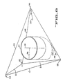
- FIGURES 5, 6, 7, 8, 9 and 10 are drawn from a three-dimensional model that was constructed to aid the inventor in the visualization and conception of his invention.
- many of the angles, such as the pitch angle of the helix, are greatly exaggerated for clarity of view.
- the various guides are represented as circles on the various planes; in fact, each circle represents the plane of the tape centerline going around a guide, and the straight lines between the guides represent the tape centerline stretched between the guides.
- the view of the drawing may be understood to have been taken as normal to the transverse plane of the guide; conversely, if a guide appears to be an ellipse, the view was taken obliquely to the plane of the guide.
- the tilt axis usually the "apparent" major elliptical axis
- FIGURE 5 is a plan view of the model looking straight down along the axis of the helical drum assembly 61, which is here shown as a hollow right-circular cylinder. Only four of the smaller tape guides are shown, namely: the fixed guides 42, 83, and the moving guides 32 and 45. Three major planes are shown, intersecting at the point 110 to define this point as the vertex of a tetrahedron having a base ABC.
- the base ABC is arbitrarily selected to provide the clearest possible illustration.
- Plane "A” is defined by the base line A and the vertex 110, and is the plane of the tape centerline going around guide 42 and along line 109 to guide 32; and the axis and generatrices of guide 42 are all normal to Plane "A". To preserve the largest possible scale for the FIGURE, Plane "A” is shown as broken off along a break line a , but it will be understood that this Plane continues to a base point 114 off the edge of the paper in FIGURES 5 and 6, but clearly shown in FIGURES 7-10.
- All of the other tape-path-defining elements associated with the cassette 13 i.e., guides 31, 43, 21, 22, 32, 33, 34, 44, 46, 47, 48, 49, the heads 51, 52, the capstan 41, and the reels 16, 17) are normal to Plane "A" as well, and the tape centerline going around these elements also lies in Plane "A", but these other elements are not shown in FIGURE 5 for the sake of clarity of illustration.
- Plane "B” is defined by the base line B and the vertex 110, and is the plane of the tape centerline going around guide 32; and the axis and generatrices of guide 32 are all normal to Plane "B".
- Plane "C” is defined by the base line C and the vertex 110, and is the plane of the tape centerline going around the guide 45; and the axis and all generatrices of guide 45 are normal to Plane "C".
- Plane “C” is also shown as broken off along a break line c , but it will be understood that Plane “C” actually continues to meet Plane "A” along line 113 and at point 114 thereon, as shown in FIGURES 7-10.
- Planes "A” and “B” intersect along line 109
- Planes “B” and “C” intersect along line 93 and at a base point 115 thereon. While the faces of the tetrahedron represented by Planes “A”, “B” and “C” are shown as solid sides, the fourth face bounded by lines A, B and C is shown as open, and the tetrahedron as hollow.
- Plane “C” is also the plane of the tape centerline going around the fixed guide 83; and the axis and generatrices of guide 83 are also normal to Plane "C".
- Plane “A” is perpetually fixed, in position and inclination, with respect to the drum 61.
- Plane “A” is tilted on an axis 78, which is a diameter of drum 61 going through the point at which the tape centerline is tangent to drum 61 on the cassette (exit) side; and the angle of inclination of Plane “A” to the drum generatrix at this point is the helix angle Beta.
- guide 42 is perpetually fixed on plane “A” and normal thereto, it follows that the illustrated tilt axis 40 for guide 42 is parallel to diameter 78 of the drum 61.
- a drum 61 diameter 80 that passes through the point at which the tape centerline is tangent to the drum on the "entrance” side, is taken as the tilt axis of Plane “C” (FIGURE 5), the tilt angle of the plane with respect to the drum 61 generatrix at this point also being the helix angle Beta.
- guides 83 and 45 in this FIGURE are both normal to Plane "C”
- their tilt axes 116 and 117 are shown as parallel to axis 80 (the guides 83 and 45 are shown in phantom because they lie beneath Plane "B” in this FIGURE).
- the tilt axis 30 of the guide 32 is shown as substantially bisecting the angle between lines 93 and 109.
- FIGURES 5-10 were chosen to be orthogonal to the planes of the major tape-path-defining elements, in such a way that each of these elements has at least one view showing it in true plan or elevation, with the other elements arranged in their various tilted relationships thereto.
- FIGURES 5-10 may be used as a substitute for the three-dimensional model from which they were taken, which if physically present could be turned around and around for study.
- the model is essentially only an irregular tetrahedron defined by point 110 and base ABC, and pierced through two faces by a right-circular cylinder.
- FIGURES 5-10 should therefore be compared point-for-point and plane-for-plane, until a full understanding of the geometric relationships is arrived at.
- FIGURE 6 is of course an oblique view showing the top of the drum 61 from above, as in FIGURE 5, but rotated somewhat away from the viewer, and the bottom of the drum 61 rotated somewhat toward the viewer.
- this view is taken substantially normal to Plane "A" (looking straight down toward the Plane). Consequently, guide 42 shows as a true circle, and guides 32 and drum 61 as foreshortened ellipses. Guides 83 and 45 cannot be seen in this FIGURE.
- the helix angle Beta is also illustrated for an intermediate point along the helical tape centerline path (dashed line) around drum 61.
- the angle Beta is defined between the common tangent 111 (to the centerline path and to the drum 61) at the point of consideration, and the drum generatrix 112 at that point.
- FIGURE 7 shows the model further rotated to bring the drum 61 into true elevation view.
- Point 114 is now clearly visible, but base line B is shown in phantom because it is hidden behind Planes "A" and "C". Only guide 42 is visible in this FIGURE.
- FIGURE 8 is taken in elevation directly on the opposite side from FIGURE 7. All the base lines A, B and C are now visible, as well as guide 32; but guides 83 and 45, which lie on Plane "C", are shown only in phantom because they are obscured by Plane "B". Guide 42 is not visible, on the far side of Plane "A”, but is indicated generally by an arrow 42.
- FIGURE 9 is taken from the same side as FIGURE 8, but obliquely from above as well.
- the FIGURE is particularly taken normal to Plane "B", so that guide 32 shows as a true circle; but guide 42 is foreshortened, and guides 45 and 83 (shown in phantom again) are foreshortened as well.
- FIGURE 10 is a view projected at the same angle as FIGURE 6, that is, from the upper left side of the model, and normal to Plane "A", but showing the apparatus in an intermediate stage of helical wrapping action: namely the 90-degree stage corresponding to that shown in FIGURE 4. While the visible portion of Plane "A” seems quite small, it still may be seen to be bounded by line A and by lines 109 and 113, and to meet the vertex 110 and base point 114.
- the base point indicated at 42 in FIGURES 5-9 is shown distended into a circular arc so as to show guide 42 as included in the portion of the Plane that is shown. It will be understood that the line A is arbitrarily selected, and is particularly selected to help the clarity of the illustration only.
- Plane “B” is shown as bounded by line B, line 109, and line 93, and includes guide 32.
- Plane “C” is shown as bounded by line C and by lines 93 and 113.
- guide 45 which in fact is co-planar with Plane “C”, as lying on the far side of line 93. It should therefore be understood that guide 45 as shown, lies in an extension of Plane "C”, and not in Plane "B".
- This error can be minimized by causing the guide 32 to tilt about an axis below the centerline level, so as to introduce a "cosine factor", resulting in a compensating error in the opposite direction.
- the net error in an actual apparatus embodying the invention amounts to only 0,33 mm over the total guide travel. This net error could be further reduced by tilting the plane in which the guide carriage travels, but it has been found satisfactory to merely shift the nominal elevation of the carriage tilt axis so as to distribute the error equally (plus and minus) over the entire travel dimension. Because the resulting error value of plus/minus 0,165 mm is within normal machining tolerances, there is no perceptible disturbance of the smooth threading operation, even when the tape is running longitudinally while being helically threaded.
- guide 45 One other accommodation, previously touched upon, is required at the end of the movement of guide 45, when it approaches and passes the fixed guide 83. If the guide 45 is mounted to run too exactly at the helix angle Beta all around the drum 61, then when it moves another ten degrees beyond the guide 83 to its final position, it will not be strictly axially parallel to guide 83; or, in other words, guide 45 will be tilted about an axis 116 (FIGURE 5) that lies in Plane "C", as it should, but that is not parallel to the tilt axis 117 of guide 83, as it ought to be, in order to keep the tensioned tape on the so-called "natural" path during operation, without tending to climb off the ends of any of the guides, even those with no flanges, and also without substantial frictional abrasion against the flanges of guides that have them.
- axis 116 FIG. 5
- the present invention contemplates mounting the guide 45 so that it is strictly normal to Plane "C" in its final position, and thus strictly axially-parallel to guide 83, with the result that it is slightly axially-inclined with respect to guide 83 when it is passing guide 83 ten degrees earlier in its path of rotation around drum 61.
- effecting means "without making any material difference in the operation of the apparatus".
- FIGURE 11 illustrates one possible arrangement for moving the guide 45 around the drum 61.
- a rotating plate 121 is mounted to rotate on the same axis as the drum 61, and is driven by a cable or belt 122 and motor 123 (which also drives a cable or belt for moving the guide 32, not shown in this FIGURE).
- a cam element 124 Below the drum 61 is fixed a cam element 124, having a cam groove 126 formed therein, which for most of its circuit is helical, at the same pitch as the helical track of the tape.
- the guide 45 is mounted upon a parallel-motion slide 127, having two rails 128, 129, which ride snugly but slidably in corresponding openings in the plate 121; and the lower end of the slide 127 is provided with a cam-follower tracking wheel 131 that rides snugly in the groove 126.
- the groove has a downwardly-curving beginning portion 132, which permits the guide 45 to stand-by, during loading of the cassette, in a position below the initial loading plate 12, and then to come up behind the run 73 (FIGURES 1 and 2) as the helical wrapping portion of the threading process begins.
- FIGURES 12 and 13 illustrate the structure of a carriage 141 for the guide 32.
- An elongated carriage plate 142 is provided to mount the guide 32 for tilting action on an axis 143 parallel to the length of plate 142.
- the plate 142 has a pair of flanged tracking wheels 146, 147 at its extremities, riding on a pair of generally diverging curved rails 148, 149 that are formed as the edges of an opening in a plate 151 that is mounted in the apparatus parallel to the initial plane 12.
- the carriage 142 is retained between the rails 148, 149 by means of a second elongated plate 152 that is pivotably connected to plate 142 on the same axis as that of wheel 146, and carries a third flanged wheel 153 at the other end, riding on the rail 149.
- the combination is spring loaded to "jacknife" the plates 142, 152 toward one another, thus to keep the generally triangular arrangement wedged snugly between the rails as they diverge or converge, depending upon the carriage position.
- the guide is rotated so as to keep the line of the tape centerline, which is normal to the tilting axis 143, always pointed toward the guide 42. Tilting of the guide at the correct angle is controlled by a wheel 154, rotating coaxially on a downward extension of guide 32, and springloaded against a third appropriately curved rail 156.
- FIGURES 1-13 illustrate the structure of the invention somewhat schematically, for the sake of clarity in describing the geometrical and other relationships between parts. To complete the description in greater detail, FIGURES 14-19 have been chosen to show the precise structural details of the mechanism.
- FIGURES 14 and 15 the parts as numbered in FIGURES 1-3 are shown in their actual forms and relative dimensions.
- the FIGURES are not strictly orthographic, but are perspectives, FIGURE 14 being taken substantially in plan, and FIGURE 15 substantially in front elevation.
- the controller 56 is not shown, nor the cassette 13, but the guides 21, 22 of the cassette are represented by a pair of support posts 21a, 22a that are mounted as part of the actual structure of the transport for use with a test cassette of modified structure; but the posts 21a, 22a may be removed when the transport is used with an actual cassette 13 as shown in FIGURES 1-3.
- the structure for introducing and ejecting the cassette 13 is not shown, either.
- the transport is shown mounted in a rack-type structure comprising a pair of side panels 201, a cross-brace member 202, and a base plate 203, which is not identical with, but is parallel to, the plate or plane 12 of FIGURES 1-3, and to the schematically illustrated Plane "A" of FIGURES 5-10.
- Plane "A” was of course the plane corresponding to the centerline of the tape in its monoplanar arrangement (FIGURE 2), and is illustrated schematically in FIGURE 15 at substantially eye-level, considering that the FIGURE is a perspective rendition.
- the drum 61 is shown in FIGURES 14-15 as mounted at the helix angle on the base plate 203, with a rotating upper portion 204 having shallow helical grooves 206 directed diagonally across the tape path so as to pump air toward the tape centerline from the upper edge of the tape to provide an air-bearing film for the tape of carefully controlled thickness.
- the upper drum portion 204 rotates in clockwise direction (arrow 206, FIGURE 14), opposite to the direction of tape motion during helical-scan "forward" operation.
- a number of transducing heads such as the head 207 (FIGURE 16) are mounted on the upper rotating drum 204, and a helical flange 208, best shown in FIGURE 16, is affixed to the lower, non-rotating portion 209 of the guide drum structure 61 for supporting and guiding the lower edge of the tensioned tape in its helical path around the drum structure 61.
- a capstan motor 211 is affixed to the base plate 203 by means of bolts 212, and the tape-engaging portion of the capstan 41 is provided with an array of openings 213 for application of vacuum suction to the back of the tape for increasing the driving grip thereon, as described.
- the suction or pressure differential may be applied to the openings 213 as by means of interior passageways arranged in any of several ways known in the art, not here shown.
- a motor 216 is mounted in suspension from a plate 217 that is in turn mounted on the base plate 203 by means of legs 218, and the arm 68, bearing guide 31 is coupled to the shaft of the motor; and the arm 68 is protected at either end of its arc of motion by rubber bumpers 219 that are mounted on the plate 151, which, along with the lower guide plate 156 (FIGURE 12), is mounted on the base plate 203 by means of legs 219.
- a mounting block 221 is also mounted on the base plate 203 to support a motor 222, on the shaft of which is mounted the arm 69 bearing the guide 34.
- all of the tape guides are air lubricated for floating the tape substantially frictionlessly on a pressurized air film.
- the air is supplied through hoses (not shown) coupled to respective input nozzles 226 and 227, and thence through interior passages (not shown) within the respective arms 68 and 69, and within the guides 31, 34, which have numerous tiny surface openings, too small to be portrayable in FIGURES 14-19, communicating with the interior passages in the zones covered by the tape during operation. All of these openings and passages may be of forms known in the art and are not here shown.
- FIGURES 14 and 15 are the various other guides and elements shown in FIGURE 1, including guide 42, which is mounted to depend from a bridge member 231, and which is supplied with air from a hose not shown and a nozzle 232; also guide 43 depending from bridge 231 and supplied with air through nozzle 233; also guide 32, which is supplied with air from a nozzle 234; also guide 33 supplied with air through a nozzle (not visible in the FIGURE); also guide 44, which is suspended from an adjustable mounting block 237 mounted on the bridge 231, and has an air nozzle 238; also guide 46, supplied with air through nozzle 239; also guides 47 and 48, supplied with air through a nozzle 241; also an air/suction nozzle 242 for the capstan 41 (FIGURE 15); also an air nozzle 243 for the guide 49; also the heads 51, 52.
- guide 42 which is mounted to depend from a bridge member 231, and which is supplied with air from a hose not shown and a nozzle 232
- guide 43 depending from bridge 231
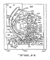
- FIGURES 14 and 15 Also shown in FIGURES 14 and 15 is a stationary central cap 246 for the scanning drum structure 61, from which leads (not shown) may be taken out for connecting the rotary heads and other circuits to the controller; a massive mounting block 247 for mounting the guide 83 and for locking the guide 45 precisely in its final position and supplying lubricating air thereto, which will be described in greater detail in reference to FIGURES 16 and 17 below, as will also a locking means 250 for the guide 33; and a driving pulley 248 and wire-strand belts 251 and 252, respectively for the carriage 141 of guide 32 and for a mounting-ring structure 253 for the guide 45, which structures are somewhat different from those of FIGURES 11 and 12, and will be described in greater detail in connection with FIGURE 16 below.
- the drum assembly 61 is shown, with the mounting arrangement for guide 45, as if isolated from the remainder of the apparatus shown in FIGURES 14 and 15, and also as if rotated about 180 degrees from the position shown in FIGURE 14, for clarity of illustration.
- FIGURE 16 is different from that schematically illustrated in FIGURE 11, in that a parallel motion linkage mechanism 253 is added to further ensure the maintenance of the correct inclination angle in the guide 45 as it moves vertically while circuiting the drum assembly during helical threading of the tape.
- This linkage includes a pair of springy beryllium copper rings 301 and 302, which are mounted in parallel as by means of six angularly spaced brackets 303 each comprising a spacing sleeve 304 between the rings, and a bolt 306 holding the two rings and sleeve together.
- Two of the brackets 303 on either side of the guide 45, also secure a pair of rigid clamping plates 307 for each ring 301, 302, so that in the vicinity of the guide 45 the rings are never flexed, but remain perpetually normal to the axis of the drum assembly 61.
- Another double set of plates 307 is provided for the pair of brackets 303 diametrically opposite to the pair shown in the foreground in FIGURE 16, but the farther brackets are behind the drum assembly 61 and are consequently not visible in FIGURE 16, although they may be seen in plan view in FIGURE 14.
- This farther pair of brackets 303 serves also to mount the ring assembly solidly to a rotating ring mount 308, while the foreground brackets 303, and the two flanking brackets to be seen in FIGURE 16, are arranged to pass freely through bores (not shown) in the rotating ring member 308.
- a set of four upwardly-inclined and four downwardly-inclined running wheels 309 are mounted on the inner periphery of the ring 308, and are angularly spaced and alternately arranged (upwardly and downwardly inclined) around the periphery, so as to engage and run on a pair of upwardly and downwardly inclined track surfaces 309 formed in a mounting drum member 311, which in turn is mounted on the base plate 203.
- the member 311 contains the guide groove 132 in which runs the guide wheel 131 for controlling the elevation of the guide 45.
- the wheel 131 is cantilevered on an arm 312 that pivots vertically on a pin 313 extending from a base member 314 into which one of the bolts 306 is threaded; and the arm 312 is locked in a chosen adjusted position by means of a clamping screw 316 threaded into the member 314.
- the axes of wheels 309 are each inclined at about 30 degrees to the vertical and the wheels are mounted as by means of ballbearing races 321 on shafts 322, which in turn are fixed in conforming bores in the ring member 308 as by means of set screws 323.
- the ring member 308 has a peripheral groove 324 which serves as a seat for several turns (not shown in FIGURE 16) of the wire-strand cable 252, by which the guide 45 is driven in rotation from driving pulley 248 (FIGURE 14).
- a mounting block 331 for the guide 45 is secured by bolts or screws (not shown in FIGURE 16) to the underside of the upper set of plates 307 in the vicinity of the desired location for the guide 45, and the ring member 308 is cut away in the vicinity of the block to permit the block to slide freely up and down with respect to the ring 308.
- the block 331 has a slot-shaped vertical bore 332 formed therein for the body of a lower extension portion 333 of the guide 45, from which protrudes a horizontal pivot pin 334 that in turn rides in, and is journaled in, a conforming horizontal groove.
- pin 334 in the groove is precisely normal to the plane of the tape that extends between the drum assembly 61 and guide 45.
- the longer (in a horizontal direction) sides of the slot 332 are strictly normal to the pin 334, and are spaced apart for just a sightly greater dimension than the pin diameter, so as to snugly guide the pin in pivoting motion in a plane parallel to the tape extending between drum assembly 61 and guide 45.
- the guide 45 can be adjusted to the desired angle "effectively" equal to the helix angle as previously defined. The adjustment method will be described in greater detail below.
- a pair of set-screws 337 are threaded into the block 331 to engage the guide extension body portion 333.
- These screws 337 are directed axially-normal to one another but at 45 degrees to the pivoting plane of guide 45, so that to change the inclination of the guide 45, one screw must be backed off, while the other is tightened.
- the initial adjusting process will be further described below.
- the pulley 248 is fixed to a central shaft 341 that is driven by a motor that is mounted below the plate 203 and is not here shown.
- the pulley has two driving portions 342 and 343, of different diameters; the upper portion 342 for the carriage 141 of the guide 32 and its wire-strand cable 251 (FIGURE 14), and the lower portion 343 for the ring member 253 and its cable 252.
- the cables fit around the pulley in several (e.g., five) turns of a helical threaded groove cut into the pulley 248 to prevent the turns from overlapping.
- the block assembly 247 includes a base block 351 upon which is mounted an upper flanged plate 352, which can be adjustably moved in a plane generally parallel to the tape run between drum 61 and guide 83, and can be clamped to the base block 351 by clamping bolts 353 (FIGURE 14), which pass through enlarged openings in the plate 352.
- An upstanding portion 354 of the plate 352 is provided with a flat gauge face 356 which is adjusted to be parallel to the desired plane of the tangential run of tape extending between drum assembly 61 and guide 83, before the bolts 353 are tightened.
- the guide 83 itself extends downwardly from a bracket 357, which extends horizontally in cantilevered fashion from a base portion 358 having a flat gauge face (not shown) fitting against the face 356 of member 352.
- the member 357 may thus be slidably adjusted along face 356 for horizontal and vertical positioning of guide 83, and for adjusting the angular inclination of the guide until precisely the helix angle is obtained for the guide, and then the member 357 may be clamped in the usual way to the member 352 as by means of clamping bolts and screws (not shown).
- Air may be supplied under pressure to guide 83, through a hose (not shown), a nozzle 361, and interior passages, also not shown, leading to openings on the tape-confronting surface of guide 83, for floating the tape frictionlessly around the guide during operation.
- a similar way of adjusting the inclination of guide 45 is also provided for in the assembly 247.
- a plate 362 is formed for sliding adjustably upon the surface 356 of member 352, and for being clamped thereto by not-shown clamping bolts in the usual manner.
- Upon the upper and lower extremities of plate 362 are bolted a pair of parallel plates 363 and 364, which extend in cantilever fashion from the plate 362 and terminate in hooked portions opening toward and receiving the guide 45 at the termination of its threading circuit around the drum assembly 61.
- the hooked portions of plates 363 and 364 engage and cradle the upper and lower extremities of the guide 45, which is shown in phantom in its terminal position.
- a clamping arm 366 (FIGURE 18) is then activated, as by sensing means (not shown) and controller 56, to swing out and engage the midportion of the guide 45 on the side thereof opposite the hooked portions of plates 363 and 364, and to clamp the guide against the hooked portions of the plates.
- the arm 366 pivots on a shaft 365 that is mounted between plates 363 and 364, and is swung by means of a toggle-arm 367 and spring-loaded variable length link 368 assembly attached to the arm 366 and to a rotary solenoid 369, which in turn is mounted on the member 362.
- link 368 When assembly is open (solid lines FIGURE 18), link 368 is in tension, but when the assembly is closed (phantom lines, FIGURE 18), the spring portion of line 368 is in compression.
- the solenoid 369 may be arranged to be actuated either to open or to close the arm 366, the return force in either case being a spring means, incorporated into the solenoid mechanism and not here shown.
- the arm 366 is also made use of to supply air under pressure to guide 45 in its terminal operating position, as by means of a hose (not shown) and nozzle 370 to the arm 366, and interior passages in the arm leading to an orifice 371 that is circumvallated by a rubber o-ring 372, which sealingly engages a flat face of the guide 45 midportion, in which is formed an air-receiving opening communicating with interior passages in the guide 45 and leading to openings in the tape-confronting surfaces of the guide.
- test tape is threaded onto the machine, with the guide 45 in its terminal position, but with the set-screws 337 both backed-off (loosened) so that the guide is free to pivot on its pivot pin 334.
- the test tape is then run longitudinally and the inclination of the plate 362 is adjusted, with its hook-shaped cradling arms 363 and 364 engaging and tilting the guide 45, until it is apparent that the tape is running in its "natural" path, i.e., without unduly rubbing against the edge-guiding flanges of any of the guides it passes around.
- the plate 362 is clamped in position, and then the set-screws 337 are tightened to lock the guide 45 in the inclination in which it engages both of the hook shaped arms 363 and 364.
- This adjustment is of course made in the factory, but can also be made, or corrected, in the field.
- a somewhat similar toggle-latching structure 250 (FIGURE 14) is provided for the terminal position of the guide 33.
- a mounting plate 391 is secured on legs 392 to the base plate 203, and a second rotary solenoid (not visible in FIGURE 14) is mounted on the lower side of plate 391, but with a shaft 393 of the solenoid extending upwardly from the plate.
- an arm 394 To the shaft is affixed an arm 394, which is connected through a link member 395 (identical to link 368) to an end of a pivoting arm 396, which pivots on a pivot pin 397 so as to retract, and then re-engage, a hook-shaped end 398 of the arm 396, when the guide 33 approaches, or is to be released.
- the precise terminal position of the guide 33 is established by means of an adjustable stop element 399, which is mounted for adjustable sliding motion on, and for being clamped to, a vertical flat face of a base block 400, which is mounted on the base plate 203.
- the solenoid may be rotated anticlockwise as seen in FIGURE 14; and for engaging the hook portion 398, the solenoid is actuated to rotate the arm 394 in a clockwise direction.
- the solenoid operating shaft 393 may also be arranged to be actuated either to open or to close the arm 394, the return force in either case being a spring means incorporated in the solenoid.
Landscapes
- Registering, Tensioning, Guiding Webs, And Rollers Therefor (AREA)
- Transmissions By Endless Flexible Members (AREA)
- Automatic Tape Cassette Changers (AREA)
- Organic Insulating Materials (AREA)
- Adhesive Tapes (AREA)
- Advancing Webs (AREA)
- Belt Conveyors (AREA)
- Supports For Plants (AREA)
- Treatment Of Fiber Materials (AREA)
Abstract
Description
- This invention relates to magnetic tape information storage and retrieval apparatus, and particularly to such apparatus capable of accepting magnetic tape from cassettes and arranging the tape for processing with extreme rapidity.
- Magnetic tape cassettes, of the type having two reels lying in the same plane on parallel axes, are convenient for packaging, shipping, and storing tape. The cassette usually can be loaded in an operating device, such as a tape transport which would engage the tape therein to automatically "thread" it into an operating mode within the transport for processing. After the processing, which usually consists of writing or reading information on or from the tape, the tape must be rewound; or if the rewinding phase is to be postponed, the tape must be rewound just after threading the next time it is used, or at some convenient time between uses.
- It would therefore be of advantage to shorten the threading time, and also to be able to begin rewinding the tape during the threading process, rather than waiting until threading is completed.
- It would also be of advantage to maintain the tape under predetermined tension during fast-forward or rewind shuttling operation, which has not been attempted, so as to be able to employ a driving and "metering" (speed-controlling) capstan and fixed transducing heads engaging the oxide recording surface of the tape, to facilitate searching operations, for locating desired blocks of information, for example, or cueing, or time-code striping, or audio play.
- Particularly when the cassette is used with so-called "helical scanning" drums, which need considerable time for threading, it would be advantageous to perform such supernumerary operations either during the threading operation itself, or without needing to wait for the full threading operation to be completed.
- In contemporary helical-scan apparatus, it is necessary to fully thread the helical tape path in order to engage the tension control mechanisms, and the introduction of the capstan, either outside the tape loop, or as a "pop-up" inside the loop, is complicated by the use of pinch rollers, and by the fact that the oxide surface of the tape faces to the outside of the cassette.
- It is known from for example EP-A-0115075 to provide a tape transport for receiving a magnetic tape cassette of the kind having a pair of tape reels and a segment of tape between said reels disposed for access by threading and operating elements, the tape transport including means for tensioning said tape and a capstan mounted for engaging and transporting said tape longitudinally, said capstan being mounted between said reels and said tape segment in the position wherein said cassette is loaded in said tape transport. The invention is characterised by a pair of movable guides mounted on the opposite side of said segment remote from said capstan, said movable guides being movable towards said segment and said capstan on paths bracketing said capstan, so as to move said segment into engaged and wrapped relation around a substantial portion of the capstan periphery and so as to provide a substantial frictional driving grip between said capstan and tape when said tape is tensioned.
- Preferably the said movable guides are mounted on a pivoting plate and substantially along a pivoting radius thereof at a spacing slightly greater than the diameter of the capstan, so as to follow concentric arcuate paths bracketing said capstan and to move said tape into said wrapped relation around said capstan when said plate is pivoted.
- In a preferred form of the invention the means for tensioning the tape tensions said segment across said capstan and transducing means in a position of said segment corresponding to a longitudinal-scanning mode of operation of said apparatus, the tape transport further comprising helical-tape-scanning means mounted near said longitudinal-scanning position of said segment and including a drum assembly; and means for disposing at least a portion of said tape segment in transducing relation with said helical-scanning means to define a helical-scanning mode of operation of said apparatus, the said means for disposing being operable while the transport is in the said longitudinal scanning mode and the tape is tensioned.
- In the preferred embodiment of the invention, the capstan is arranged with a plurality of other guides and longitudinal transducing heads in a loading plane, into which the reels of a cassette are brought for loading, along axial paths that are normal to the plane, with the capstan and certain "interior" ones of the guides interposed in the tape "loop" that is defined between the reels and the run of tape extending between the reels. Certain of the guides exterior to the cassette are then moved inwardly along the loading plane to bracket the capstan and to bring a portion of the tape run into wrapping configuration around the capstan. Concurrently, certain of the interior guides are moved outwardly along the loading plane to bring another portion of the tape run into transducing relation with the heads; and at least two other of the interior guides, mounted at the ends of tensioning arms, are moved outwardly to tension the entire tape run against the heads and capstan, and to dispose a straight segment of the tape run in nearly tangential relation to (but not in contact with) the helical scanning drum, which is inclined at the desired helix angle with respect to the loading plane. In this intermediate condition, the tape may be processed longitudinally entirely in the loading plane. For helical threading, a first threading guide is obtruded into the tape loop and circulated helically around the scanning drum, inclined at the helix angle with respect to the drum, while another of the interior guides moves outwardly along the loading plane in an arcuate path around and beyond the scanning drum, inclined at changing angles with respect to the loading plane, these angles being carefully predetermined so as to maintain the tape in longitudinally transportable and processible condition, both during threading from, and unthreading to, the intermediate condition.
-
- FIGURE 1 is a schematic plan view tape transport mechanism incorporating a preferred embodiment of the present invention in an initial loading position;
- FIGURE 2 is a schematic plan view showing the mechanism of FIGURE 1 in the intermediate processing position;
- FIGURE 3 is a schematic plan view showing the mechanism of FIGURE 1 in the fully threaded position;
- FIGURE 4 is a schematic plan view, to an enlarged scale, illustrating the movements of the helical threading guides from the intermediate to the fully threaded position;
- FIGURE 5 is a schematic plan view, taken along the scanning drum axis, of a model illustrating the geometry of the invention;
- FIGURE 6 is a schematic view taken normal to the initial loading plane, of the model of FIGURE 5;
- FIGURE 7 is a schematic elevation view, taken normal to the drum axis, of the model of FIGURES 5 and 6;
- FIGURE 8 is a schematic elevation view, taken from the side opposite that of FIGURE 7, of the model of FIGURES 5-7;
- FIGURE 9 is a schematic oblique view, taken from above and from the same side as that of FIGURE 8, of the model of FIGURES 5-8;
- FIGURE 10 is a schematic oblique view, taken from above and from the same side as FIGURE 6, and from the same direction normal to the initial loading plane, of the model of FIGURES 5-9, illustrating a beginning portion of the helical-threading process;
- FIGURE 11 is a schematic perspective view illustrating the operation of one arrangement for the helical threading guide;
- FIGURE 12 is a schematic plan view illustrating the operation of the planar-moving helical threading guide;
- FIGURE 13 is a schematic elevation view of the mechanism shown in FIGURE 12;
- FIGURE 14 is perspective plan view of an actual structure embodying the invention;
- FIGURE 15 is a perspective front elevation view of the apparatus shown in FIGURE 14;
- FIGURE 16 is a cross-sectional left side elevation perspective view, to an enlarged scale, of a portion of the apparatus shown in FIGURES 14 and 15;
- FIGURE 17 is a cross-sectional elevation view, to an further enlarged scale, of a portion of the apparatus shown in FIGURES 14 and 15, and is taken substantially along the line 17-17 of FIGURE 14; and
- FIGURE 18 is a cross-sectional plan view to the scale of FIGURE 17, and taken substantially along the line 18-18 of FIGURE 17.
- Referring now to the drawings, and particularly to FIGURES 1-3, which schematically outline the operation of the apparatus of the invention, there is shown a magnetic
tape transport machine 11, and particularly atape deck 12 consisting of a flat plate defining an initial loading plane. Upon this plate is positionedmagnetic tape cassette 13, having oneopen side 14, and containing a pair ofreels 16 and 17 upon which amagnetic tape 18 is wound, with the recording surface facing outward, and with arun 19 of tape stretched between the reels and across theopen side 14 of the cassette as by means of guides, or support posts, 21 and 22. - The cassette is brought to the
plate 12 by a loading apparatus, not shown, and approaches the plate along a path that is normal to theplate 12 and parallel to theaxes guides plane 12, are caused to obtrude into a cut-out zone defined byedges 36 of the cassettelower side wall 37. Theupper side wall 38 of the cassette is shown as broken-away except at the lower corners. The cassette is retained in the illustrated position onplane 12 by means not shown, and thereels 16, 17 are coupled to tape tensioning and driving motors, also not shown in FIGURES 1-3. - It will be noted that the interior guides 31-34 obtrude into the space between the
reels 16, 17 and therun 19 of tape stretched between the reels. Also obtruding into this space is a large-diameter capstan 41, which is also axially normal to plane 12. Also normal toplane 12 are a number of "exterior"elements heads capstan 41, andheads guides elements plane 12 during the operation of the transport, although they (except the heads) may be rotatable about their own axes. Theother guides - As shown in FIGURES 1 and 2, the first step to be performed in readying the tape for operation, is to engage it with the capstan and the transducing heads and to apply the tape-tensioning system for so-called "longitudinal" operation in the
plane 12, but disengaged from thehelical scanning drum 61. This step is performed automatically under the control of acontroller 56, which produces control signals generally indicated at 57, in response to commands from an operator, and also in response to state and condition signals generated by elements of theapparatus 11 and generally indicated at 58. Thecontroller 56 and the means producing thesignals - First the two
guides tape tensioning arms 68 and 69, pivoting onaxes elements controller 56 to permit tape to be further extracted from the cassette while controlling the tape tension by response to signals from thearms 68, 69, throughout all of the subsequent threading and operating modes of the machine. Theguides plate 62 that pivots around anaxis 63, are caused to pivot (as shown by the paths of arrows leading from these guides) to an inboard position engaging the tape run 19 and bracketing thecapstan 41 so as to wrap the tape around the capstan for a substantial portion of its circumference, about 160 degrees, and so as to provide the capstan with a good frictional grip on the tape, when the tape is under tension, without the need for a pinch roller. The capstan may be a vacuum-operated capstan, if desired, to further augment the gripping action. - At the same time, the
guide 33, which is mounted on an arm 66 pivoting about anaxis 67, is caused to engage the inboard side of the tape run 19 and to draw it outwardly and across theguide 46 andheads alignment 73, nearly tangential to but not quite touching thescanning drum 61. Thus the tape is ready for longitudinal operation, as closely as possible in readiness for helical wrapping around the scanning drum, but still entirely disposed in theplane 12, where it may be fast-wound in either direction, or transduced longitudinally by theheads capstan 41, and carefully-maintained tension control by the servoedtension arms 68 and 69, and all as directed by the operator and thecontroller 56. - To assist in the winding operations mentioned above, an end-of-tape sensing device 65 (Figures 1 and 2) is mounted on the
arm 62. Thedevice 65 comprises a U-shaped member with upstanding arms (see also Figures 14 and 15) for bracketing the tape in both the open position of the arm 62 (Figure 1) and the closed position (Figure 2). One of the upstanding arms contains a light source, and the other arm contains a photo-sensing device which is occluded from the light source when the tape is present but produces a signal to controller 56 when the tape breaks, or when the cassette is not present, or when a transparent tape leader at either end of the tape runs between the reels. - Referring now to FIGURES 2 and 3, it will be seen that, even if the tape is still being fast-wound or transduced longitudinally, the helical wrapping phase of the threading operation can be carried out without any interruption.
- To bring about the helical wrapping of the tape, it is only necessary to move the
guides scanning guide drum 61 is inclined with respect to theplane 12, and at the desired pitch angle of the helical path that the tape is eventually to follow around the drum. Actually, as shown in the FIGURES, theguide drum axis 81 is tilted about anaxis 78 normal thereto and lying inplane 12; the plane oftilt 79 of theaxis 81 being normal to theplane 12 and oriented with respect to the plane of the reel axes 23 and 24 by an angle Alpha, of about six degrees, the actual value of angle Alpha being chosen to enable the apparatus to be fitted most conveniently into the space available. - Because the
guide 44, and the guide 45 (when it first brings the tape into contact with drum 61), are arranged to be substantially normal toplane 12, it follows that they are also inclined (with respect to the drum 61) at the pitch or helix angle of the helical tape path around the drum. As will be seen below, guide 45 is mounted on a plate that is normal to theaxis 81 of thedrum 61, and rotates about thatsame axis 81. Consequently, throughout its circuit of the threadingpath 77, theguide 45 is constantly inclined at substantially the helix angle and is thus able to lay the tape on its helical path with the tape centerline in its passage around theguide 45 lying always in a plane that is normal to the axis of theguide 45. The extreme importance of this geometric condition will be made clear below. - Of course the
guide 45, in order to move from the position indicated, outside thetape run 73, to the inside, and then to engage the inboard side of thetape run 73 and then follow a helical path around thedrum 61, it (the guide 45) must start from beneath the level of plane 12 (as shown in the drawings, or alternatively from above, though this would be less convenient in the illustrated structure), and rise intoplane 12 insideloop 73, and then descend again in thehelical path 77 arounddrum 61; and mechanism to effect this function will be described further below. Suffice to say, with relation to FIGURES 2 and 3, that, at the end of the circuit forguide 45, the tape is wrapped around the drum in contact therewith for a wrap angle" of 210 degrees and comes tangentially away from the drum to be bent around aguide post 83, which is fixed in position at the helix angle with respect to drum 61. Theguide 83 is called the "entrance" guide, and theguide 44 the "exit" guide, because during normal forward scanning of the tape, it is moving in an anti-clockwise direction (as seen in the FIGURES) around thedrum 61. - While the
guide 45 is making its circuit around thedrum 61, theguide 32 is also caused to move along its path 76, from a position inside the cassette, and in a generally straight path to engage the inboard side of tape run 73 at apoint 94 near fixedguide 42, and thence around to afinal position 91, which is chosen so that the tape in its final disposition (FIGURE 3) lies in two straight runs, namely, arun 92 betweenguide 42 andposition 91, and arun 93 betweenposition 91 and the final position ofguide 45. The controlling criteria are that the tape in runs 92 and 93 should be spaced sufficiently fromdrum 61 to avoid frictional contact, theguide 32 should remain inplane 12 throughout its movement, and the the tape should be twisted at all times only about its centerline, but with the centerline in circuit around guides 42, 32 and 45 being always in planes substantially normal to the respective guide axes, thus fulfilling the well-known condition for keeping the tensioned tape in a "natural" path, without any tendency to climb off the end of any of the guides, particularly if they are rotatable guides. Thus, if edge guides are used to keep the tape in its correct plane in the event of sudden slackness, such edge guides cause the minimum amount, if any, of abrasion and edge wear of the tape. - It is important to recognize that the path of
guide 32, from itsintersection 94 with thetape run 73, could follow a straight line inplane 12 all the way to the final position 91 (in other words, guide 32 could follow theline 92 instead of the line 76), provided theguides 31 and 42 (and line 92) were located a somewhat greater distance to the left as shown in FIGURES 1-3, so that thetape run 92 did not interfere withdrum 61 orguide 45. Such a geometrical arrangement would greatly simplify the tracking arrangements forguide 32, as will be seen below, but would require more space than was available in the present machine. Also a differential speed movement betweenguides - While the
guide 45 has been described above as being mounted so as to be "substantially" normal to plane 12 at the point at which it first brings the tape into contact withdrum 61, and has also been described as inclined with respect to drum 61 at "substantially" the helix angle at that point, and throughout its circuit of the drum, it (guide 45) is in practice mounted at an angle that represents a slight departure from the helix angle, for reasons that will be more easily understood at a later point in this description. - Turning now to FIGURE 4, the actual positions of the
guides drum 61 are illustrated to bring out certain other considerations affecting the choice of guide paths. It will be understood that, in order to avoid the complication of differential-speed movements of the two guides, it is desirable to move them both at constant speeds from beginning to end of the wrapping operation, and to ensure that both guides end their movements at the same time. For this purpose, they are both driven by belts or cables (described below) from the same drive motor. However, the successive positions of the two guides must be phased so that the tape runs 101, 102, 103, 104, 105, 106, and 107, between theguides guides - It will also be noted, in relation to FIGURE 4, that
guide 32, in following curved path 76, must constantly increase its tilt in aplane 108 that is normal to the tape centerline running betweenguides guide 32. Furthermore, since this centerline direction is constantly changing, it follows that theguide 32 must be rotated (as seen in plan view) somewhat clockwise more and more in its carriage during the movement, while at the same time being steadily tilted more and more. This requirement for two degrees of angular control, instead of only one, is a complication that could be avoided if the path 76 is made to be straight instead of curved, for then the line of the tape centerline would be constantly pointed at the same angle towardguide 42, and control of tilt only would be needed. - In FIGURE 4, it will be understood that the tape centerline between
guides guides guide 45 encounters the tape (point 94, FIGURE 2), to tilt in a plane that intersects the first plane along aline 113, for each of the angular positions of theguides point 110 that is somewhat removed fromguide 32. If theguide 32 had infinitely small diameter, thepoint 110 would substantially coincide with theguide 32. To put the matter another way, the generatrices at which the twocenterlines 109 and 101-107 become tangent to the right circular-cylindrical guide 32 would be identical if the guide had zero diameter; but because the diameter is finite, the point at which the centerline leaves guide 32 in the direction ofguide 45 is thrown below the level ofline 109. This effect, and a correction that must be made to accommodate it, will be more clearly described in connection with FIGURES 5-10, described below. - FIGURES 5, 6, 7, 8, 9 and 10 are drawn from a three-dimensional model that was constructed to aid the inventor in the visualization and conception of his invention. In this model, many of the angles, such as the pitch angle of the helix, are greatly exaggerated for clarity of view. However, the principles remain the same. The various guides are represented as circles on the various planes; in fact, each circle represents the plane of the tape centerline going around a guide, and the straight lines between the guides represent the tape centerline stretched between the guides. Consequently, if a guide appears to be represented by a true circle, the view of the drawing may be understood to have been taken as normal to the transverse plane of the guide; conversely, if a guide appears to be an ellipse, the view was taken obliquely to the plane of the guide. To assist in recognizing such tilted guides, the tilt axis (usually the "apparent" major elliptical axis) has been shown in each case.
- FIGURE 5 is a plan view of the model looking straight down along the axis of the
helical drum assembly 61, which is here shown as a hollow right-circular cylinder. Only four of the smaller tape guides are shown, namely: the fixed guides 42, 83, and the movingguides point 110 to define this point as the vertex of a tetrahedron having a base ABC. The base ABC is arbitrarily selected to provide the clearest possible illustration. - Plane "A" is defined by the base line A and the
vertex 110, and is the plane of the tape centerline going around guide 42 and alongline 109 to guide 32; and the axis and generatrices ofguide 42 are all normal to Plane "A". To preserve the largest possible scale for the FIGURE, Plane "A" is shown as broken off along a break line a, but it will be understood that this Plane continues to abase point 114 off the edge of the paper in FIGURES 5 and 6, but clearly shown in FIGURES 7-10. - All of the other tape-path-defining elements associated with the cassette 13 (i.e., guides 31, 43, 21, 22, 32, 33, 34, 44, 46, 47, 48, 49, the
heads capstan 41, and thereels 16, 17) are normal to Plane "A" as well, and the tape centerline going around these elements also lies in Plane "A", but these other elements are not shown in FIGURE 5 for the sake of clarity of illustration. - Plane "B" is defined by the base line B and the
vertex 110, and is the plane of the tape centerline going around guide 32; and the axis and generatrices ofguide 32 are all normal to Plane "B". - Plane "C" is defined by the base line C and the
vertex 110, and is the plane of the tape centerline going around theguide 45; and the axis and all generatrices ofguide 45 are normal to Plane "C". In FIGURES 5 and 6, Plane "C" is also shown as broken off along a break line c, but it will be understood that Plane "C" actually continues to meet Plane "A" alongline 113 and atpoint 114 thereon, as shown in FIGURES 7-10. - For completeness' sake, it should be mentioned that Planes "A" and "B" intersect along
line 109, while Planes "B" and "C" intersect alongline 93 and at abase point 115 thereon. While the faces of the tetrahedron represented by Planes "A", "B" and "C" are shown as solid sides, the fourth face bounded by lines A, B and C is shown as open, and the tetrahedron as hollow. - When
guide 45 is in its terminal (fully-threaded) position, as shown in FIGURE 5, then Plane "C" is also the plane of the tape centerline going around the fixedguide 83; and the axis and generatrices ofguide 83 are also normal to Plane "C". - It will be understood that Plane "A" is perpetually fixed, in position and inclination, with respect to the
drum 61. Plane "A" is tilted on anaxis 78, which is a diameter ofdrum 61 going through the point at which the tape centerline is tangent to drum 61 on the cassette (exit) side; and the angle of inclination of Plane "A" to the drum generatrix at this point is the helix angle Beta. Becauseguide 42 is perpetually fixed on plane "A" and normal thereto, it follows that the illustratedtilt axis 40 forguide 42 is parallel todiameter 78 of thedrum 61. - Likewise, a
drum 61diameter 80, that passes through the point at which the tape centerline is tangent to the drum on the "entrance" side, is taken as the tilt axis of Plane "C" (FIGURE 5), the tilt angle of the plane with respect to thedrum 61 generatrix at this point also being the helix angle Beta. And, becauseguides tilt axes guides - However Planes "B" and "C" must be understood to vary in position and inclination throughout the helical-threading process, as will be more fully explained below. It is only at the end of this threading process that guides 32 and 45, and their associated Planes "B" and "C", occupy the dispositions shown in FIGURE 5.
- One further observation may be made with respect to FIGURE 5: the
tilt axis 30 of theguide 32 is shown as substantially bisecting the angle betweenlines - FIGURES 5-10 were chosen to be orthogonal to the planes of the major tape-path-defining elements, in such a way that each of these elements has at least one view showing it in true plan or elevation, with the other elements arranged in their various tilted relationships thereto. In this sense, FIGURES 5-10 may be used as a substitute for the three-dimensional model from which they were taken, which if physically present could be turned around and around for study. The model is essentially only an irregular tetrahedron defined by
point 110 and base ABC, and pierced through two faces by a right-circular cylinder. FIGURES 5-10 should therefore be compared point-for-point and plane-for-plane, until a full understanding of the geometric relationships is arrived at. - FIGURE 6 is of course an oblique view showing the top of the
drum 61 from above, as in FIGURE 5, but rotated somewhat away from the viewer, and the bottom of thedrum 61 rotated somewhat toward the viewer. In particular, this view is taken substantially normal to Plane "A" (looking straight down toward the Plane). Consequently, guide 42 shows as a true circle, and guides 32 and drum 61 as foreshortened ellipses.Guides drum 61. The angle Beta is defined between the common tangent 111 (to the centerline path and to the drum 61) at the point of consideration, and thedrum generatrix 112 at that point. - FIGURE 7 shows the model further rotated to bring the
drum 61 into true elevation view.Point 114 is now clearly visible, but base line B is shown in phantom because it is hidden behind Planes "A" and "C". Only guide 42 is visible in this FIGURE. - FIGURE 8 is taken in elevation directly on the opposite side from FIGURE 7. All the base lines A, B and C are now visible, as well as
guide 32; but guides 83 and 45, which lie on Plane "C", are shown only in phantom because they are obscured by Plane "B".Guide 42 is not visible, on the far side of Plane "A", but is indicated generally by anarrow 42. - FIGURE 9 is taken from the same side as FIGURE 8, but obliquely from above as well. The FIGURE is particularly taken normal to Plane "B", so that
guide 32 shows as a true circle; but guide 42 is foreshortened, and guides 45 and 83 (shown in phantom again) are foreshortened as well. - FIGURE 10 is a view projected at the same angle as FIGURE 6, that is, from the upper left side of the model, and normal to Plane "A", but showing the apparatus in an intermediate stage of helical wrapping action: namely the 90-degree stage corresponding to that shown in FIGURE 4. While the visible portion of Plane "A" seems quite small, it still may be seen to be bounded by line A and by
lines vertex 110 andbase point 114. The base point indicated at 42 in FIGURES 5-9 is shown distended into a circular arc so as to showguide 42 as included in the portion of the Plane that is shown. It will be understood that the line A is arbitrarily selected, and is particularly selected to help the clarity of the illustration only. Likewise, Plane "B" is shown as bounded by line B,line 109, andline 93, and includesguide 32. Plane "C" is shown as bounded by line C and bylines guide 45, which in fact is co-planar with Plane "C", as lying on the far side ofline 93. It should therefore be understood that guide 45 as shown, lies in an extension of Plane "C", and not in Plane "B". - It will be noted, particularly in FIGURE 8, how the finite diameter of
guide 32 causes a dropping of thecenterline line 93, which is also the line of intersection between Planes "B" and "C", so that it extends from thepoint 110, exterior to theguide 32, as previously mentioned. Likewise, the center point of the guide (i.e., the point at which the guide axis passes through the Plane "C") also is caused to drop out of Plane "A". Consequently, if the carriage (described below), that moves guide 32 along its threading path, moves in a plane parallel to Plane "A", a guide elevation error can result. This error can be minimized by causing theguide 32 to tilt about an axis below the centerline level, so as to introduce a "cosine factor", resulting in a compensating error in the opposite direction. The net error in an actual apparatus embodying the invention (see FIGURES 14 et seq.) amounts to only 0,33 mm over the total guide travel. This net error could be further reduced by tilting the plane in which the guide carriage travels, but it has been found satisfactory to merely shift the nominal elevation of the carriage tilt axis so as to distribute the error equally (plus and minus) over the entire travel dimension. Because the resulting error value of plus/minus 0,165 mm is within normal machining tolerances, there is no perceptible disturbance of the smooth threading operation, even when the tape is running longitudinally while being helically threaded. - One other accommodation, previously touched upon, is required at the end of the movement of
guide 45, when it approaches and passes the fixedguide 83. If theguide 45 is mounted to run too exactly at the helix angle Beta all around thedrum 61, then when it moves another ten degrees beyond theguide 83 to its final position, it will not be strictly axially parallel to guide 83; or, in other words, guide 45 will be tilted about an axis 116 (FIGURE 5) that lies in Plane "C", as it should, but that is not parallel to thetilt axis 117 ofguide 83, as it ought to be, in order to keep the tensioned tape on the so-called "natural" path during operation, without tending to climb off the ends of any of the guides, even those with no flanges, and also without substantial frictional abrasion against the flanges of guides that have them. - Such a problem can be solved by mounting the
guide 45 in its carrier so as to have ten degrees of extra rotation. Other complex structural solutions are also possible. However, in the present invention, a slight bias in the alignment of theguide 45 is tolerable during the helical threading process, so long as the guide alignment is substantially correct after it arrives in its final position and during protracted helical-scanning operation of the apparatus. - Accordingly, the present invention contemplates mounting the
guide 45 so that it is strictly normal to Plane "C" in its final position, and thus strictly axially-parallel to guide 83, with the result that it is slightly axially-inclined with respect to guide 83 when it is passingguide 83 ten degrees earlier in its path of rotation arounddrum 61. This means that at the instant of passingguide 83, and actually throughout its rotation from initial contact with the tape, guide 45 is inclined, not exactly, but effectively at the helix angle Beta. In this use, the term "effecting" means "without making any material difference in the operation of the apparatus". - One possible variation of the above described geometry is to place the
guide 42 upon the line 113 (see FIGURE 5), which is the line of intersection between Planes "A" and "C". This disposition would result geometrically in Plane "B" becoming identical with Plane "C", with the practical result that all of the twist would take place betweenguides guides - FIGURE 11 illustrates one possible arrangement for moving the
guide 45 around thedrum 61. Arotating plate 121 is mounted to rotate on the same axis as thedrum 61, and is driven by a cable orbelt 122 and motor 123 (which also drives a cable or belt for moving theguide 32, not shown in this FIGURE). Below thedrum 61 is fixed acam element 124, having acam groove 126 formed therein, which for most of its circuit is helical, at the same pitch as the helical track of the tape. Theguide 45 is mounted upon a parallel-motion slide 127, having tworails plate 121; and the lower end of theslide 127 is provided with a cam-follower tracking wheel 131 that rides snugly in thegroove 126. The groove has a downwardly-curvingbeginning portion 132, which permits theguide 45 to stand-by, during loading of the cassette, in a position below theinitial loading plate 12, and then to come up behind the run 73 (FIGURES 1 and 2) as the helical wrapping portion of the threading process begins. - FIGURES 12 and 13 illustrate the structure of a
carriage 141 for theguide 32. Anelongated carriage plate 142 is provided to mount theguide 32 for tilting action on anaxis 143 parallel to the length ofplate 142. Theplate 142 has a pair offlanged tracking wheels curved rails plate 151 that is mounted in the apparatus parallel to theinitial plane 12. Thecarriage 142 is retained between therails elongated plate 152 that is pivotably connected to plate 142 on the same axis as that ofwheel 146, and carries a thirdflanged wheel 153 at the other end, riding on therail 149. The combination is spring loaded to "jacknife" theplates axis 143, always pointed toward theguide 42. Tilting of the guide at the correct angle is controlled by awheel 154, rotating coaxially on a downward extension ofguide 32, and springloaded against a third appropriatelycurved rail 156. -
- It is to be understood that FIGURES 1-13 illustrate the structure of the invention somewhat schematically, for the sake of clarity in describing the geometrical and other relationships between parts. To complete the description in greater detail, FIGURES 14-19 have been chosen to show the precise structural details of the mechanism.
- Referring particularly to FIGURES 14 and 15, the parts as numbered in FIGURES 1-3 are shown in their actual forms and relative dimensions. The FIGURES are not strictly orthographic, but are perspectives, FIGURE 14 being taken substantially in plan, and FIGURE 15 substantially in front elevation. The
controller 56 is not shown, nor thecassette 13, but theguides support posts posts actual cassette 13 as shown in FIGURES 1-3. The structure for introducing and ejecting thecassette 13 is not shown, either. The transport is shown mounted in a rack-type structure comprising a pair ofside panels 201, across-brace member 202, and abase plate 203, which is not identical with, but is parallel to, the plate orplane 12 of FIGURES 1-3, and to the schematically illustrated Plane "A" of FIGURES 5-10. Plane "A" was of course the plane corresponding to the centerline of the tape in its monoplanar arrangement (FIGURE 2), and is illustrated schematically in FIGURE 15 at substantially eye-level, considering that the FIGURE is a perspective rendition. - The
drum 61 is shown in FIGURES 14-15 as mounted at the helix angle on thebase plate 203, with a rotatingupper portion 204 having shallowhelical grooves 206 directed diagonally across the tape path so as to pump air toward the tape centerline from the upper edge of the tape to provide an air-bearing film for the tape of carefully controlled thickness. Theupper drum portion 204 rotates in clockwise direction (arrow 206, FIGURE 14), opposite to the direction of tape motion during helical-scan "forward" operation. A number of transducing heads, such as the head 207 (FIGURE 16) are mounted on the upperrotating drum 204, and ahelical flange 208, best shown in FIGURE 16, is affixed to the lower,non-rotating portion 209 of theguide drum structure 61 for supporting and guiding the lower edge of the tensioned tape in its helical path around thedrum structure 61. - For a comparative enumeration of the structural elements, we start at the base plate 203 (FIGURE 15). A
capstan motor 211 is affixed to thebase plate 203 by means ofbolts 212, and the tape-engaging portion of thecapstan 41 is provided with an array ofopenings 213 for application of vacuum suction to the back of the tape for increasing the driving grip thereon, as described. - The suction or pressure differential, may be applied to the
openings 213 as by means of interior passageways arranged in any of several ways known in the art, not here shown. - A
motor 216 is mounted in suspension from aplate 217 that is in turn mounted on thebase plate 203 by means oflegs 218, and the arm 68, bearingguide 31 is coupled to the shaft of the motor; and the arm 68 is protected at either end of its arc of motion by rubber bumpers 219 that are mounted on theplate 151, which, along with the lower guide plate 156 (FIGURE 12), is mounted on thebase plate 203 by means of legs 219. A mountingblock 221 is also mounted on thebase plate 203 to support amotor 222, on the shaft of which is mounted thearm 69 bearing theguide 34. - In the structure shown in FIGURES 14-19, all of the tape guides (except
guide 45 during threading only) are air lubricated for floating the tape substantially frictionlessly on a pressurized air film. Forguides respective input nozzles respective arms 68 and 69, and within theguides - Also shown in FIGURES 14 and 15 are the various other guides and elements shown in FIGURE 1, including
guide 42, which is mounted to depend from abridge member 231, and which is supplied with air from a hose not shown and anozzle 232; also guide 43 depending frombridge 231 and supplied with air throughnozzle 233; also guide 32, which is supplied with air from anozzle 234; also guide 33 supplied with air through a nozzle (not visible in the FIGURE); also guide 44, which is suspended from anadjustable mounting block 237 mounted on thebridge 231, and has anair nozzle 238; also guide 46, supplied with air throughnozzle 239; also guides 47 and 48, supplied with air through anozzle 241; also an air/suction nozzle 242 for the capstan 41 (FIGURE 15); also anair nozzle 243 for theguide 49; also theheads - Also shown in FIGURES 14 and 15 is a stationary
central cap 246 for thescanning drum structure 61, from which leads (not shown) may be taken out for connecting the rotary heads and other circuits to the controller; amassive mounting block 247 for mounting theguide 83 and for locking theguide 45 precisely in its final position and supplying lubricating air thereto, which will be described in greater detail in reference to FIGURES 16 and 17 below, as will also a locking means 250 for theguide 33; and a drivingpulley 248 and wire-strand belts carriage 141 ofguide 32 and for a mounting-ring structure 253 for theguide 45, which structures are somewhat different from those of FIGURES 11 and 12, and will be described in greater detail in connection with FIGURE 16 below. - Referring to FIGURE 16, the
drum assembly 61 is shown, with the mounting arrangement forguide 45, as if isolated from the remainder of the apparatus shown in FIGURES 14 and 15, and also as if rotated about 180 degrees from the position shown in FIGURE 14, for clarity of illustration. - The structure of FIGURE 16 is different from that schematically illustrated in FIGURE 11, in that a parallel
motion linkage mechanism 253 is added to further ensure the maintenance of the correct inclination angle in theguide 45 as it moves vertically while circuiting the drum assembly during helical threading of the tape. - This linkage includes a pair of springy beryllium copper rings 301 and 302, which are mounted in parallel as by means of six angularly spaced
brackets 303 each comprising aspacing sleeve 304 between the rings, and abolt 306 holding the two rings and sleeve together. Two of thebrackets 303, on either side of theguide 45, also secure a pair ofrigid clamping plates 307 for eachring guide 45 the rings are never flexed, but remain perpetually normal to the axis of thedrum assembly 61. Another double set ofplates 307 is provided for the pair ofbrackets 303 diametrically opposite to the pair shown in the foreground in FIGURE 16, but the farther brackets are behind thedrum assembly 61 and are consequently not visible in FIGURE 16, although they may be seen in plan view in FIGURE 14. This farther pair ofbrackets 303 serves also to mount the ring assembly solidly to arotating ring mount 308, while theforeground brackets 303, and the two flanking brackets to be seen in FIGURE 16, are arranged to pass freely through bores (not shown) in therotating ring member 308. - To mount and guide the
ring member 308 in rotation, a set of four upwardly-inclined and four downwardly-inclined running wheels 309 are mounted on the inner periphery of thering 308, and are angularly spaced and alternately arranged (upwardly and downwardly inclined) around the periphery, so as to engage and run on a pair of upwardly and downwardly inclined track surfaces 309 formed in a mountingdrum member 311, which in turn is mounted on thebase plate 203. Themember 311 contains theguide groove 132 in which runs theguide wheel 131 for controlling the elevation of theguide 45. Thewheel 131 is cantilevered on anarm 312 that pivots vertically on apin 313 extending from abase member 314 into which one of thebolts 306 is threaded; and thearm 312 is locked in a chosen adjusted position by means of a clampingscrew 316 threaded into themember 314. The axes ofwheels 309 are each inclined at about 30 degrees to the vertical and the wheels are mounted as by means ofballbearing races 321 onshafts 322, which in turn are fixed in conforming bores in thering member 308 as by means of setscrews 323. Thering member 308 has a peripheral groove 324 which serves as a seat for several turns (not shown in FIGURE 16) of the wire-strand cable 252, by which theguide 45 is driven in rotation from driving pulley 248 (FIGURE 14). - Of great importance in the mounting of
guide 45 is the structure for gauge-mounting and adjusting the precise inclination of the guide with respect to the helix angle, to secure the alignment conditions previously described. A mounting block 331 for theguide 45 is secured by bolts or screws (not shown in FIGURE 16) to the underside of the upper set ofplates 307 in the vicinity of the desired location for theguide 45, and thering member 308 is cut away in the vicinity of the block to permit the block to slide freely up and down with respect to thering 308. The block 331 has a slot-shapedvertical bore 332 formed therein for the body of alower extension portion 333 of theguide 45, from which protrudes ahorizontal pivot pin 334 that in turn rides in, and is journaled in, a conforming horizontal groove. The alignment ofpin 334 in the groove is precisely normal to the plane of the tape that extends between thedrum assembly 61 andguide 45. The longer (in a horizontal direction) sides of theslot 332 are strictly normal to thepin 334, and are spaced apart for just a sightly greater dimension than the pin diameter, so as to snugly guide the pin in pivoting motion in a plane parallel to the tape extending betweendrum assembly 61 andguide 45. Thus theguide 45 can be adjusted to the desired angle "effectively" equal to the helix angle as previously defined. The adjustment method will be described in greater detail below. To lock the guide in the desired angular position, a pair of set-screws 337 are threaded into the block 331 to engage the guideextension body portion 333. Thesescrews 337 are directed axially-normal to one another but at 45 degrees to the pivoting plane ofguide 45, so that to change the inclination of theguide 45, one screw must be backed off, while the other is tightened. The initial adjusting process will be further described below. - Referring now to FIGURES 17 and 18, further details of the
drive pulley 248 and guide block 247 assemblies are shown. Both assemblies are mounted on thebase plate 203 at appropriate angles. Thepulley 248 is fixed to acentral shaft 341 that is driven by a motor that is mounted below theplate 203 and is not here shown. The pulley has two drivingportions 342 and 343, of different diameters; the upper portion 342 for thecarriage 141 of theguide 32 and its wire-strand cable 251 (FIGURE 14), and thelower portion 343 for thering member 253 and itscable 252. The cables fit around the pulley in several (e.g., five) turns of a helical threaded groove cut into thepulley 248 to prevent the turns from overlapping. - The
block assembly 247 includes abase block 351 upon which is mounted an upperflanged plate 352, which can be adjustably moved in a plane generally parallel to the tape run betweendrum 61 and guide 83, and can be clamped to thebase block 351 by clamping bolts 353 (FIGURE 14), which pass through enlarged openings in theplate 352. Anupstanding portion 354 of theplate 352 is provided with aflat gauge face 356 which is adjusted to be parallel to the desired plane of the tangential run of tape extending betweendrum assembly 61 and guide 83, before thebolts 353 are tightened. Theguide 83 itself extends downwardly from abracket 357, which extends horizontally in cantilevered fashion from abase portion 358 having a flat gauge face (not shown) fitting against theface 356 ofmember 352. Themember 357 may thus be slidably adjusted alongface 356 for horizontal and vertical positioning ofguide 83, and for adjusting the angular inclination of the guide until precisely the helix angle is obtained for the guide, and then themember 357 may be clamped in the usual way to themember 352 as by means of clamping bolts and screws (not shown). Air may be supplied under pressure to guide 83, through a hose (not shown), anozzle 361, and interior passages, also not shown, leading to openings on the tape-confronting surface ofguide 83, for floating the tape frictionlessly around the guide during operation. - A similar way of adjusting the inclination of
guide 45 is also provided for in theassembly 247. Aplate 362 is formed for sliding adjustably upon thesurface 356 ofmember 352, and for being clamped thereto by not-shown clamping bolts in the usual manner. Upon the upper and lower extremities ofplate 362 are bolted a pair ofparallel plates 363 and 364, which extend in cantilever fashion from theplate 362 and terminate in hooked portions opening toward and receiving theguide 45 at the termination of its threading circuit around thedrum assembly 61. Thus, when adjusted to the desired position, the hooked portions ofplates 363 and 364 engage and cradle the upper and lower extremities of theguide 45, which is shown in phantom in its terminal position. A clamping arm 366 (FIGURE 18) is then activated, as by sensing means (not shown) andcontroller 56, to swing out and engage the midportion of theguide 45 on the side thereof opposite the hooked portions ofplates 363 and 364, and to clamp the guide against the hooked portions of the plates. Thearm 366 pivots on ashaft 365 that is mounted betweenplates 363 and 364, and is swung by means of a toggle-arm 367 and spring-loadedvariable length link 368 assembly attached to thearm 366 and to arotary solenoid 369, which in turn is mounted on themember 362. When assembly is open (solid lines FIGURE 18), link 368 is in tension, but when the assembly is closed (phantom lines, FIGURE 18), the spring portion ofline 368 is in compression. Thesolenoid 369 may be arranged to be actuated either to open or to close thearm 366, the return force in either case being a spring means, incorporated into the solenoid mechanism and not here shown. - The
arm 366 is also made use of to supply air under pressure to guide 45 in its terminal operating position, as by means of a hose (not shown) andnozzle 370 to thearm 366, and interior passages in the arm leading to anorifice 371 that is circumvallated by a rubber o-ring 372, which sealingly engages a flat face of theguide 45 midportion, in which is formed an air-receiving opening communicating with interior passages in theguide 45 and leading to openings in the tape-confronting surfaces of the guide. - The method for establishing the desired inclination for
guide 45 can now be described. A test tape is threaded onto the machine, with theguide 45 in its terminal position, but with the set-screws 337 both backed-off (loosened) so that the guide is free to pivot on itspivot pin 334. The test tape is then run longitudinally and the inclination of theplate 362 is adjusted, with its hook-shaped cradlingarms 363 and 364 engaging and tilting theguide 45, until it is apparent that the tape is running in its "natural" path, i.e., without unduly rubbing against the edge-guiding flanges of any of the guides it passes around. When this condition is achieved, theplate 362 is clamped in position, and then the set-screws 337 are tightened to lock theguide 45 in the inclination in which it engages both of the hook shapedarms 363 and 364. This adjustment is of course made in the factory, but can also be made, or corrected, in the field. - A somewhat similar toggle-latching structure 250 (FIGURE 14) is provided for the terminal position of the
guide 33. A mountingplate 391 is secured onlegs 392 to thebase plate 203, and a second rotary solenoid (not visible in FIGURE 14) is mounted on the lower side ofplate 391, but with ashaft 393 of the solenoid extending upwardly from the plate. To the shaft is affixed anarm 394, which is connected through a link member 395 (identical to link 368) to an end of a pivoting arm 396, which pivots on apivot pin 397 so as to retract, and then re-engage, a hook-shaped end 398 of the arm 396, when theguide 33 approaches, or is to be released. The precise terminal position of theguide 33 is established by means of an adjustable stop element 399, which is mounted for adjustable sliding motion on, and for being clamped to, a vertical flat face of abase block 400, which is mounted on thebase plate 203. To open the hook 398 for receiving or releasing theguide 33, the solenoid may be rotated anticlockwise as seen in FIGURE 14; and for engaging the hook portion 398, the solenoid is actuated to rotate thearm 394 in a clockwise direction. Thesolenoid operating shaft 393 may also be arranged to be actuated either to open or to close thearm 394, the return force in either case being a spring means incorporated in the solenoid. - Thus there has been described a machine for extracting tape from a cassette and for threading the tape, first to a mono-planar disposition for longitudinal shuttling and transducing operation, and second, if desired, to a helical disposition around a scanning drum assembly, with the tape following a "natural" path both during and after the second threading operation, such that the tape centerline crosses all guide generatrices, except those of the scanning drum, perpendicularly.
Claims (6)
- A tape transport for receiving a magnetic tape cassette of the kind having a pair of tape reels (16, 17) and a segment (19) of tape between said reels disposed for access by threading and operating elements, the tape transport including means (31, 34) for tensioning said tape and a capstan (41) mounted for engaging and transporting said tape longitudinally, said capstan (41) being mounted between said reels (16, 17) and said tape segment (19) in the position wherein said cassette is loaded in said tape transport; characterised by a pair of movable guides (47, 48) mounted on the opposite side of said segment (19) remote from said capstan (41), said movable guides (47, 48) being movable towards said segment (19) and said capstan (41) on paths bracketing said capstan (41), so as to move said segment (19) into engaged and wrapped relation around a substantial portion of the capstan periphery and so as to provide a substantial frictional driving grip between said capstan (41) and tape when said tape is tensioned.
- A tape transport according to claim 1, wherein said movable guides (47, 48) are mounted on a pivoting plate (62) and substantially along a pivoting radius (66) thereof at a spacing slightly greater than the diameter of the capstan (41), so as to follow concentric arcuate paths bracketing said capstan (41) and to move said tape into said wrapped relation around said capstan (41) when said plate (62) is pivoted.
- A tape transport according to claim 2 wherein a tape-sensing means (65) is also mounted on said plate (62) so as to be in operative relation with said tape in all positions of said plate (62), the tape-sensing means (65) comprising a U-shaped member with two upstanding arms positioned to bracket said tape, one of said arms containing a light source and the other containing a light-sensing means to provide a signal to motors for the reels (16, 17) whenever opaque portions of the tape are not bracketed by the arms.
- A tape transport according to any foregoing claim, wherein the means (31, 34) for tensioning the tape tensions said segment across said capstan (41) and transducing means (51, 52) in a position of said segment corresponding to a longitudinal-scanning mode of operation of said tape transport, the tape transport further comprising helical-tape-scanning means mounted near said longitudinal-scanning position of said segment and including a drum assembly (61); and means (32, 45) for disposing at least a portion of said tape segment in transducing relation with said helical-scanning means to define a helical-scanning mode of operation of said tape transport, the said means (32, 45) for disposing said tape segment in transducing relation with said helical scanning means being operable while the tape transport is in the said longitudinal scanning mode and the tape is tensioned.
- A tape transport according to claim 4 wherein said tape confronts said drum assembly (61) along generatrices thereof that are inclined, at the helix angle of the drum assembly (61), to the tape centreline, but confronts all other tape-guiding elements of the tape transport along generatrices that are substantially perpendicular to the tape centreline.
- A tape transport according to claim 4 wherein the said means (32, 45) for disposing said tape segment in transducing relation with said helical scanning means comprises a first guide (44) for disposing the segment of the tensioned tape at the beginning of a helical wrapping zone extending around the drum assembly (61), a second guide (45) for moving into engagement with said tape segment and to thereafter move at a substantial constant angle of inclination, in a helical circuit (77) around said drum, so as to wrap a portion of said tape segment in said helical zone; and a third guide (32) for guiding and tensioning the remainder of said tape in said segment and for bending a part of said remainder for movement along a trajectory spaced somewhat from said drum assembly (61), so as to hold said remainder of said tape segment out of frictional contact with said drum assembly (61) and with said drum-wrapped tape portion, and so as to cause said remainder of the tape segment to be wrapped about all of said guides perpendicularly to the generatrices thereof throughout the wrapping operation.
Priority Applications (2)
| Application Number | Priority Date | Filing Date | Title |
|---|---|---|---|
| AT86302723T ATE73952T1 (en) | 1985-04-12 | 1986-04-11 | STRIP TRANSPORT WITH QUICK EXTRACTION. |
| EP91200198A EP0429437B1 (en) | 1985-04-12 | 1986-04-11 | Fast deploying tape transport |
Applications Claiming Priority (2)
| Application Number | Priority Date | Filing Date | Title |
|---|---|---|---|
| US722924 | 1985-04-12 | ||
| US06/722,924 US4652946A (en) | 1985-04-12 | 1985-04-12 | Fast deploying tape transport |
Related Child Applications (1)
| Application Number | Title | Priority Date | Filing Date |
|---|---|---|---|
| EP91200198.9 Division-Into | 1991-02-01 |
Publications (3)
| Publication Number | Publication Date |
|---|---|
| EP0198693A2 EP0198693A2 (en) | 1986-10-22 |
| EP0198693A3 EP0198693A3 (en) | 1988-12-28 |
| EP0198693B1 true EP0198693B1 (en) | 1992-03-18 |
Family
ID=24904005
Family Applications (2)
| Application Number | Title | Priority Date | Filing Date |
|---|---|---|---|
| EP86302723A Expired - Lifetime EP0198693B1 (en) | 1985-04-12 | 1986-04-11 | Fast deploying tape transport |
| EP91200198A Expired - Lifetime EP0429437B1 (en) | 1985-04-12 | 1986-04-11 | Fast deploying tape transport |
Family Applications After (1)
| Application Number | Title | Priority Date | Filing Date |
|---|---|---|---|
| EP91200198A Expired - Lifetime EP0429437B1 (en) | 1985-04-12 | 1986-04-11 | Fast deploying tape transport |
Country Status (5)
| Country | Link |
|---|---|
| US (1) | US4652946A (en) |
| EP (2) | EP0198693B1 (en) |
| JP (1) | JPS61276155A (en) |
| AT (1) | ATE73952T1 (en) |
| DE (2) | DE3684349D1 (en) |
Families Citing this family (11)
| Publication number | Priority date | Publication date | Assignee | Title |
|---|---|---|---|---|
| US4800450A (en) * | 1986-04-11 | 1989-01-24 | Ampex Corporation | Method and apparatus for controlling deployment of a tape transport member |
| US4949203A (en) * | 1987-03-11 | 1990-08-14 | Pioneer Electronic Corporation | Tape recorder having an improved cassette mounting device |
| EP0369332A3 (en) * | 1988-11-14 | 1992-01-29 | R-Byte, Inc. | Tape guidance arrangement |
| US5093752A (en) * | 1989-02-20 | 1992-03-03 | Sony Corporation | Device for moving capstan into position after tape is loaded |
| JP2694047B2 (en) | 1989-12-06 | 1997-12-24 | 三菱電機株式会社 | Magnetic recording / reproducing device |
| JPH03183054A (en) * | 1989-12-11 | 1991-08-09 | Fuji Photo Film Co Ltd | Magnetic recording and reproducing device |
| US5739976A (en) * | 1992-09-09 | 1998-04-14 | Hitachi, Ltd. | Magnetic recording and reproducing apparatus |
| JP3085041B2 (en) * | 1993-08-25 | 2000-09-04 | 三菱電機株式会社 | Tape loading device |
| US6498699B1 (en) * | 1999-12-02 | 2002-12-24 | Storage Technology Corporation | Tape transport using a carrier ribbon |
| JP5507561B2 (en) | 2008-08-15 | 2014-05-28 | オーチス エレベータ カンパニー | Cord and polymer jacket assembly with flame retardant in polymer jacket material |
| JP5839675B2 (en) * | 2011-11-15 | 2016-01-06 | 株式会社イシダ | Packaging equipment |
Family Cites Families (9)
| Publication number | Priority date | Publication date | Assignee | Title |
|---|---|---|---|---|
| US2675973A (en) * | 1949-06-24 | 1954-04-20 | Int Electronics Co | Equipment for use with magnetic tape records |
| JPS4933824B1 (en) * | 1969-03-17 | 1974-09-10 | ||
| FR2136625A5 (en) * | 1971-04-24 | 1972-12-22 | Victor Company Of Japan | |
| JPS5435612Y2 (en) * | 1973-11-15 | 1979-10-29 | ||
| US3985277A (en) * | 1975-03-26 | 1976-10-12 | Xerox Corporation | Web handling device |
| US4056833A (en) * | 1976-03-10 | 1977-11-01 | Odetics, Inc. | Turntable assembly for video cassette recorder/reproducer |
| JPS55160362A (en) * | 1979-05-31 | 1980-12-13 | Sony Corp | Tape loader |
| JPS57212651A (en) * | 1981-06-24 | 1982-12-27 | Matsushita Electric Ind Co Ltd | Magnetic recording and reproducing device |
| JPH0644369B2 (en) * | 1982-12-28 | 1994-06-08 | オリンパス光学工業株式会社 | Magnetic recording / reproducing device |
-
1985
- 1985-04-12 US US06/722,924 patent/US4652946A/en not_active Expired - Lifetime
-
1986
- 1986-04-11 DE DE8686302723T patent/DE3684349D1/en not_active Expired - Lifetime
- 1986-04-11 DE DE3650537T patent/DE3650537T2/en not_active Expired - Lifetime
- 1986-04-11 AT AT86302723T patent/ATE73952T1/en not_active IP Right Cessation
- 1986-04-11 EP EP86302723A patent/EP0198693B1/en not_active Expired - Lifetime
- 1986-04-11 EP EP91200198A patent/EP0429437B1/en not_active Expired - Lifetime
- 1986-04-11 JP JP61083975A patent/JPS61276155A/en active Pending
Also Published As
| Publication number | Publication date |
|---|---|
| EP0198693A3 (en) | 1988-12-28 |
| EP0198693A2 (en) | 1986-10-22 |
| US4652946A (en) | 1987-03-24 |
| DE3650537T2 (en) | 1996-11-14 |
| EP0429437B1 (en) | 1996-06-26 |
| ATE73952T1 (en) | 1992-04-15 |
| EP0429437A2 (en) | 1991-05-29 |
| EP0429437A3 (en) | 1992-03-04 |
| DE3684349D1 (en) | 1992-04-23 |
| DE3650537D1 (en) | 1996-08-01 |
| JPS61276155A (en) | 1986-12-06 |
Similar Documents
| Publication | Publication Date | Title |
|---|---|---|
| EP0198693B1 (en) | Fast deploying tape transport | |
| US4837646A (en) | Tape guide apparatus for helically wound tape | |
| KR850001454B1 (en) | Video disc player | |
| EP0068758B1 (en) | Signal-recording/reproducing apparatus | |
| US5701214A (en) | Tape loading device in magnetic recording/playback apparatus that controls loading based on calculated reel inertia and tape position | |
| US4413293A (en) | Magnetic tape transport | |
| JPH02192059A (en) | Magnetic recording/reproducing device | |
| US4943874A (en) | Tape tension controller for a cassette recording/playback apparatus | |
| US3984870A (en) | Magnetic video recording and reproducing apparatus having a tape threading mechanism | |
| US4964557A (en) | Bidirectional web guiding system | |
| US4951163A (en) | Magnetic recording and reproducing apparatus | |
| US4012793A (en) | Multioriented composite-surface tape guide for use in a cassette | |
| US5739976A (en) | Magnetic recording and reproducing apparatus | |
| JPH0644369B2 (en) | Magnetic recording / reproducing device | |
| US5343339A (en) | Tape loading device with selective tape loading characteristic for magnetic recording/reproducing apparatus | |
| US4964002A (en) | Magnetic recording and reproducing apparatus having a pair of skew guide blocks | |
| US5243477A (en) | Apparatus for threading magnetic tape from a single reel cartridge in a rotary head tape transport | |
| JP2810139B2 (en) | Recording and playback device | |
| US3720794A (en) | Dual magnetic tape cassette transport and carrousel apparatus | |
| US5204791A (en) | Tape loading device of a video tape recorder having a linkage driven inclined auxiliary tape guide member | |
| GB1562404A (en) | Web cassettes and web guiding members therefor | |
| KR950003079B1 (en) | Tape odometer of magnetic record player | |
| WO1992022897A1 (en) | Magnetic tape threading and guiding system for a helical scan recorder | |
| JPS61273769A (en) | Tape loading device | |
| JP2863251B2 (en) | Magnetic recording / reproducing device |
Legal Events
| Date | Code | Title | Description |
|---|---|---|---|
| PUAI | Public reference made under article 153(3) epc to a published international application that has entered the european phase |
Free format text: ORIGINAL CODE: 0009012 |
|
| AK | Designated contracting states |
Kind code of ref document: A2 Designated state(s): AT CH DE FR GB LI NL |
|
| PUAL | Search report despatched |
Free format text: ORIGINAL CODE: 0009013 |
|
| AK | Designated contracting states |
Kind code of ref document: A3 Designated state(s): AT CH DE FR GB LI NL |
|
| 17P | Request for examination filed |
Effective date: 19881228 |
|
| 17Q | First examination report despatched |
Effective date: 19900531 |
|
| GRAA | (expected) grant |
Free format text: ORIGINAL CODE: 0009210 |
|
| AK | Designated contracting states |
Kind code of ref document: B1 Designated state(s): AT CH DE FR GB LI NL |
|
| REF | Corresponds to: |
Ref document number: 73952 Country of ref document: AT Date of ref document: 19920415 Kind code of ref document: T |
|
| XX | Miscellaneous (additional remarks) |
Free format text: TEILANMELDUNG 91200198.9 EINGEREICHT AM 11/04/86. |
|
| PGFP | Annual fee paid to national office [announced via postgrant information from national office to epo] |
Ref country code: AT Payment date: 19920409 Year of fee payment: 7 |
|
| REF | Corresponds to: |
Ref document number: 3684349 Country of ref document: DE Date of ref document: 19920423 |
|
| ET | Fr: translation filed | ||
| PLBE | No opposition filed within time limit |
Free format text: ORIGINAL CODE: 0009261 |
|
| STAA | Information on the status of an ep patent application or granted ep patent |
Free format text: STATUS: NO OPPOSITION FILED WITHIN TIME LIMIT |
|
| 26N | No opposition filed | ||
| PG25 | Lapsed in a contracting state [announced via postgrant information from national office to epo] |
Ref country code: AT Effective date: 19930411 |
|
| PGFP | Annual fee paid to national office [announced via postgrant information from national office to epo] |
Ref country code: CH Payment date: 19930420 Year of fee payment: 8 |
|
| PGFP | Annual fee paid to national office [announced via postgrant information from national office to epo] |
Ref country code: NL Payment date: 19930430 Year of fee payment: 8 |
|
| REG | Reference to a national code |
Ref country code: GB Ref legal event code: 732E |
|
| PGFP | Annual fee paid to national office [announced via postgrant information from national office to epo] |
Ref country code: GB Payment date: 19940405 Year of fee payment: 9 |
|
| PG25 | Lapsed in a contracting state [announced via postgrant information from national office to epo] |
Ref country code: LI Effective date: 19940430 Ref country code: CH Effective date: 19940430 |
|
| NLS | Nl: assignments of ep-patents |
Owner name: AMPEX SYSTEMS CORPORATION TE REDWOOD CITY, CALIFOR |
|
| PG25 | Lapsed in a contracting state [announced via postgrant information from national office to epo] |
Ref country code: NL Effective date: 19941101 |
|
| NLV4 | Nl: lapsed or anulled due to non-payment of the annual fee | ||
| REG | Reference to a national code |
Ref country code: CH Ref legal event code: PL |
|
| PG25 | Lapsed in a contracting state [announced via postgrant information from national office to epo] |
Ref country code: GB Effective date: 19950411 |
|
| GBPC | Gb: european patent ceased through non-payment of renewal fee |
Effective date: 19950411 |
|
| PGFP | Annual fee paid to national office [announced via postgrant information from national office to epo] |
Ref country code: DE Payment date: 20050407 Year of fee payment: 20 |
|
| PGFP | Annual fee paid to national office [announced via postgrant information from national office to epo] |
Ref country code: FR Payment date: 20050408 Year of fee payment: 20 |