EP0198638A2 - Ölbohrlochmessgeräte zur Anwendung in offenen Bohrlöchern und in gekapselten Bohrsonden mittels Messung des paramagnetischen Effektes - Google Patents
Ölbohrlochmessgeräte zur Anwendung in offenen Bohrlöchern und in gekapselten Bohrsonden mittels Messung des paramagnetischen Effektes Download PDFInfo
- Publication number
- EP0198638A2 EP0198638A2 EP86302525A EP86302525A EP0198638A2 EP 0198638 A2 EP0198638 A2 EP 0198638A2 EP 86302525 A EP86302525 A EP 86302525A EP 86302525 A EP86302525 A EP 86302525A EP 0198638 A2 EP0198638 A2 EP 0198638A2
- Authority
- EP
- European Patent Office
- Prior art keywords
- formation
- magnetic field
- earth
- excitation zone
- oil
- Prior art date
- Legal status (The legal status is an assumption and is not a legal conclusion. Google has not performed a legal analysis and makes no representation as to the accuracy of the status listed.)
- Withdrawn
Links
Images


Classifications
-
- G—PHYSICS
- G01—MEASURING; TESTING
- G01R—MEASURING ELECTRIC VARIABLES; MEASURING MAGNETIC VARIABLES
- G01R33/00—Arrangements or instruments for measuring magnetic variables
- G01R33/20—Arrangements or instruments for measuring magnetic variables involving magnetic resonance
- G01R33/24—Arrangements or instruments for measuring magnetic variables involving magnetic resonance for measuring direction or magnitude of magnetic fields or magnetic flux
-
- G—PHYSICS
- G01—MEASURING; TESTING
- G01R—MEASURING ELECTRIC VARIABLES; MEASURING MAGNETIC VARIABLES
- G01R33/00—Arrangements or instruments for measuring magnetic variables
- G01R33/02—Measuring direction or magnitude of magnetic fields or magnetic flux
- G01R33/022—Measuring gradient
-
- G—PHYSICS
- G01—MEASURING; TESTING
- G01V—GEOPHYSICS; GRAVITATIONAL MEASUREMENTS; DETECTING MASSES OR OBJECTS; TAGS
- G01V3/00—Electric or magnetic prospecting or detecting; Measuring magnetic field characteristics of the earth, e.g. declination, deviation
- G01V3/18—Electric or magnetic prospecting or detecting; Measuring magnetic field characteristics of the earth, e.g. declination, deviation specially adapted for well-logging
- G01V3/32—Electric or magnetic prospecting or detecting; Measuring magnetic field characteristics of the earth, e.g. declination, deviation specially adapted for well-logging operating with electron or nuclear magnetic resonance
-
- Y—GENERAL TAGGING OF NEW TECHNOLOGICAL DEVELOPMENTS; GENERAL TAGGING OF CROSS-SECTIONAL TECHNOLOGIES SPANNING OVER SEVERAL SECTIONS OF THE IPC; TECHNICAL SUBJECTS COVERED BY FORMER USPC CROSS-REFERENCE ART COLLECTIONS [XRACs] AND DIGESTS
- Y02—TECHNOLOGIES OR APPLICATIONS FOR MITIGATION OR ADAPTATION AGAINST CLIMATE CHANGE
- Y02A—TECHNOLOGIES FOR ADAPTATION TO CLIMATE CHANGE
- Y02A90/00—Technologies having an indirect contribution to adaptation to climate change
- Y02A90/30—Assessment of water resources
Definitions
- This invention relates to the new type of nuclear magnetic resonance method and apparatus which remotely senses and detects the presence of unknown petroleum reservoirs in geological formations and also allows the direct measurement of significant portions of oil and water fluid volume contained within the reservoirs.
- the new method directly measures natural paramagnetism of the formation of measurement of a new physical "effect” called the Paramagnetic Logging Effect - (PLE).
- PLE Paramagnetic Logging Effect -
- Nuclear paramagnetism was first measured at very low temperatures on solid hydrogen (G.B. Lasarew and L.W. Schubnikow, Phys. Z. Sowjet, 11, p. 445, 1937). In this experiment the sample's paramagnetism was observed during the temperature cycling. However, for ordinary sized laboratory samples at room temperature, nuclear paramagnetism becomes extraordinarily feeble and difficult to measure. Consequently, many other experimental techniques known collectively as nuclear magnetic resonance techniques were developed to observe the nuclear magnetic moments of nucleons in solids and liquids.
- Nuclear magnetic resonance measurements are classified into “continuous wave” and “pulse” methods. Continuous wave observations of nuclear magnetic resonance are performed using power absorption measurements or nuclear induction arrangements (E.R. Andrew, Nuclear Magnetic Resonance, Cambridge Univ. Press, N.Y., p. 34, 1955). Pulse methods, also known as free precession techniques, have been developed in recent years - (T.C. Farrar and E.D. Becker, Pulse and Fourier Transform NMR, Academic Press, N.Y., p.1, 1971).
- nuclear magnetic moment executes a precessional motion around a static magnetic field.
- the nuclear magnetic moment may be due to a single proton within an atomic nucleus which is also called an "unpaired" proton or is the actual vector sum of nuclear magnetic moments of the protons, neutrons, and other particles which comprise the atomic nucleus, hereafter referred to collectively as nucleons.
- nucleons For the discussion of the motions of such particles in applied A.C. magnetic fields, these several terms may be used interchangeably.
- the proton's magnetic moment processes at a Larmor frequency of approximately 2.1 kilohertz.
- the tip of the magnetic moment vector traces out a cone- shaped motion around the static magnetic field. If a large number of magnetic moments are placed in the earth's magnetic field, similar motion ensues except that the tips of the magnetic vectors fan out around the same cone. The fact that some of the nuclear magnetic moments have net components along the direction of the magnetic field causes the sample's paramagnetism.
- Standard nuclear magnetic resonance methods are currently being used to measure the properties of oil reservoirs immediately adjacent to boreholes. See for examples U.S. Pat. Nos. 4,035,718 (1977); 3,667,035 (1972); 3,657,730 (1972); 3,617,867 - (1971); 3,508,438 (1970); 3,483,465 (1969); 3,439,260 (1969); 3,395,337 (1968); etc. These methods are collectively described as polarization-precession methods. Normally, a strong magnetic field is applied to the oil bearing formation which polarizes the nuclear moments present into a coherent magnetization. The strong magnetic field is then turned off rapidly. Consequently, the freely precessing nuclear moments in the earth's magnetic field are measured by sensing the A.C.
- an object of the invention is to provide a new and practical nuclear magnetic resonance method for the remote detection and direct volumetric measurement of petroleum reserves.
- an object of the invention is to provide new and practical nuclear magnetic resonance methods and apparatus for the remote detection of the presence of unknown petroleum reservoirs in geological formations.
- Figure 1 shows a preferred embodiment of the apparatus for remote sensing and volumetric measurement of petroleum reserves. This particular embodiment is appropriate when extensive drilling has already occurred in the oil field.
- Two boreholes, 10 and 12 respectively, have been drilled from the earth's surface 14. As is shown, the boreholes have drilled through the oil bearing formation 16.
- a standard frequency sweep oscillator 18 has an output which drives an A.C. power amplifier 22.
- This frequency sweep oscillator - (F.S.O.) must be capable of slowly frequency sweeping around approximately 2.1 kHz. and the power amplifier (P.A.) must be capable of providing significant A.C. current near the frequency of 2.1 kHz.
- A.C. current is conducted through the oil bearing formation in paths collssctively identified as 32 in Fig. 1.
- the total A.C. current passing through the oil bearing formation produces an A.C. magnetic field throughout the oil bearing strata. For example, at a location labeled 34 within the formation, there exists an A.C. magnetic field whose vector is primarily out of the drawing. The magnitude of the A.C. magnetic field but not the frequency depends on location in the formation.
- the frequency of 2.1 kHz is the Larmor frequency of protons in the nominal strength of the earth's magnetic field of 0.5 gauss. Therefore, a means is provided whereby a significant portion of the oil bearing formation may be subjected to an A.C. magnetic field at the Larmor frequency of protons in the earth's magnetic field. Furthermore, a means is provided whereby a significant portion of an oil bearing formation may be swept through a condition of nuclear magnetic resonance.
- the significant portion of the oil bearing formation subject to the applied A.G. magnetic field is also called the "excitation zone" of the formation. As will be rigorously defined later, this is the zone wherein the motion of the magnetic moments become substantially affected by the application of the A.C. magnetic field. In essence, the excitation zone is that zone in the formation where the application of the A.C. magnetic field causes the paramagnetism of the fluids contained therein to disappear or at least be substantially reduced in magnitude.
- a borehole magnetometer assembly labeled as 36 in Fig. 1 is lowered into borehole 12 a distance Z above the center of the oil bearing formation.
- the borehole magnetometer assembly includes a large number of turns of insulated wire 38 which are wound around a very high permeability magnetic core material 40 which is in turn connected to an amplifier 42.
- This amplifier must be stable and have high gain, extremely low noise, narrow bandwidth, and excellent low frequency response.
- a relatively new integrated circuit which is very well suited for this purpose is the OP-27A/E (Precision Monolithics Inc., 1500 Space Park Drive, Santa Clara, CA 95050). This operational amplifier has a very low input noise voltage density of 5 nanovolts per square-root hertz at a frequency of 10 hertz.
- the required low noise and high gain are obtained using standard electronic design principles and several OP-27A/E integrated circuits.
- the output of this amplifier is connected to a shielded cable 44 which leaves the borehole and is connected to the input of a standard signal averager 46.
- the signal averager (S.A.) obtains its reference sync. pulse via a cable 48 which is connected to the sync. pulse output of the frequency swept oscillator. Consequently, a means has been provided which measures the low frequency variation or amplitude modulation in the earth's magnetic field. Measurements at various positions Z provide a means whereby the variation in the earth's magnetic field can be measured in the vicinity of the excitation zone.
- a means has been provided to sweep a significant portion of the oil bearing reservoir otherwise also called an "excitation zone" of the formation through a condition of nuclear magnetic resonance.
- the application of the A.C. magnetic field at the Larmor frequency causes a randomization, or “scrambling,” of the directions of the nuclear magnetic moments which were initially aligned in the magnetic field of the earth and which in turn cause the initial paramagnetism of the formation.
- This randomization process is also called the "excitation process" of the formation and occurs within the "excitation zone" of the formation.
- the paramagnetism of the oil in formation is decreased or eliminated within this zone.
- the paramagnetism of the excitation zone of the oil formation contributes to the total magnetic field measured by the magnetometer. Consequently, as the excitation zone of the oil formation is swept through the condition of nuclear magnetic resonance, or resonance conditions, a small decrease in the earth's magnetic field in the vicinity of the excitation zone is observed. This decrease in the magnetic field strength is directly related to the volume of liquid petroleum and water contained within the volume defined by the excitation zone in the formation.
- the first step is applying an A.C. magnetic field at frequencies near or including the Larmor frequency to a portion of the oil bearing formation defined as the excitation zone of the formation, thereby placing the excitation zone of the formation into a state of nuclear magnetic resonance.
- This state of nuclear magnetic resonance in turn alters the natural nuclear paramagnetism of the formation within the excitation zone which results in a change in the earth's magnetic field in the vicinity of the excitation zone of the formation.
- the second step is while placing the excitation zone of the formation into a state of nuclear magnetic resonance, measurements are simultaneously performed detecting any change in the earth's magnetic field in the vicinity of the excitation zone due to changes in the natural nuclear paramagnetism of the excitation zone to indicate the presence of absence of petroleum and other fluids such as water within the excitation zone of the formation.
- the nucleons relax back along the earth's magnetic field direction with characteristic times called longitudinal relaxation times.
- the water present in formation has a characteristic longitudinal relaxation time (or ranges of times).
- This relaxation process causes the earth's magnetic field in the vicinity of the excitation zone 4 to return to its prior value before the excitation of the formation.
- a single excitation-relaxation process causes a single variation in the earth's magnetic field.
- a variation in the earth's magnetic field is defined by an initial decrease followed by an increase in the earth's magnetic field caused by one sweep through resonance.
- a method is proposed wherein the frequency of the A.C. magnetic field applied to the excitation zone of the formation is swept from a frequency below the Larmor frequency to a frequency above the Larmor frequency of the protons and other nucleons within the excitation zone where after the sweep through the Larmor frequency the protons and other nucleons which have been disrupted in alignment with the earth's magnetic field direction relax back along the earth's magnetic field direction with characteristic longitudinal relaxation times where the excitation-relaxation process results in a variation in the earth's magnetic field which is simultaneously measured to indicate the presence or absence of petroleum within the excitation zone.
- This excitation-relaxation process may be repetitiously repeated by suitably adjusting the repetition rate of the sweep oscillator.
- the sweep oscillator repetitiously sweeps the excitation zone of the formation through a condition of nuclear magnetic resonance, thereby repetitiously amplitude modulating the paramagnetism of the formation.
- This excitation-relaxation process results in a repetitive variation in the earth's magnetic field which results in an amplitude modulation of the earth's magnetic field in the vicinity of the excitation zone of the formation.
- the amplitude modulation of the earth's magnetic field in the vicinity'of the excitation zone is measured by the induction coil magnetometer.
- the signal averager is used to increase the signal and decrease the noise using standard experimental techniques.
- a method is proposed in which the frequency of the A.C. magnetic field applied to the excitation zone of the formation is repeatedly swept from a frequency below the Larmor frequency to a frequency above the Larmor frequency at such a suitable sweep rate that the protons and other nucleons within the excitation zone are driven into a state of nuclear magnetic resonance in such a manner that substantial disrupts the orientation of the protons and other nucleons in the earth's magnetic field within the excitation zone and after the sweep through the Larmor frequency the protons and other nucleons which have been disrupted in alignment with the earth's static magnetic field relax back along the earth's magnetic field direction with characteristic longitudinal relaxation times and where the excitation-relaxation process is repeated at a suitable repetition rate thereby resulting in an amplitude modulation of the natural nuclear paramagnetism of the excitation zone of the formation which results in the amplitude modulation of the earth's magnetic field in the vicinity of the excitation zone of the formation and simultaneously detecting the amplitude modulation in the
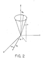
- the motion of a collection of nuclear magnetic moments is described with reference to a coordinate frame as shown in Fig. 2.
- the magnetic field of the earth is B o and lies along the Z axis of the coordinate frame.
- An individual magnetic moment U precesses in a conic motion around the direction of B o in the absence of other magnetic fields.
- the magnetic moment executes this type of motion because the time rate of change of the vector angular momentum (dUdt) must equal the vector torque on the magnetic moment (U X So), as shown in Eq. 1:
- This type of motion is described by locating the angular position of the tip of the magnetic moment U with respect to the X axis in Fig. 2. This angular position is defined by the angle 6 in Fig. 2. The time rate of change of the angle is called the angular precession frequency w o .
- This angular frequency is related to the earth's magnetic field and to the gyromagnetic ratio of the proton y by the following equation:
- Equation 2 is a consequence of Equation 1.
- the many individual magnetic moments fan out around the cone at different angles 6 as shown in Fig. 2.
- M z the nuclear paramagnetism of petroleum.
- An external magnetic field B is applied to the precessing magnetic moments as shown in Fig. 2.
- B is confined to the X-Y plane, has constant magnitude, and rotates in time through the angle ⁇ which is defined in Fig. 2.
- B must only have a non-parallel component to B o for the validity of the following analysis (B, must be at a non-zero angle to B o ).
- T is the longitudinal relaxation time and T 2 is the transverse relaxation time.
- T is the time it takes for the disoriented magnetic moments to achieve thermal equilibrium and hence realign along the Z axis after the conditions of saturation have been achieved. Therefore, T, is called the thermal relaxation time, also called the spin-lattice time.
- T 2 is the time it takes .
- T 2 is also called the spin-spin relaxation time.
- the minimum required strength B, to achieve randomization of the magnetic moments is approximately 37 milligauss. Consequently, if an A.C. magnetic field of 37 milligauss is applied to an oil bearing formation at the Larmor frequency, saturation will occur. Furthermore, it is well known that most transverse relaxation times are longer than 10- 4 sec (see Eq. 6). This therefore would require a minimum A.C. field strength of only 11.7 milligauss to achieve saturation. Consequently, it has been shown that there is a minimum A.C. magnetic field strength necessary to produce saturation which is related to the relaxation properties of the oil bearing formation.
- Eq. 8 the transit time through resonance At must certainly be less than the longitudinal relaxation time T,. From Eq. 5, the minimum longitudinal relaxation time is 0.1 second and therefore Eq. 8 specifies in this worst case that the magnitude of the required A.C. magnetic field to cause excitation is approximately 0.37 milligauss. This is a very small magnetic field. For example, if an A.C. current of 10 amps (peak-to-peak) were passed through a localized area of the petroleum reservoir, the A.C. magnetic field produced by this current would exceed 0.37 gauss (peak-to-peak) inside a radius of 54 meters. Therefore, useful measurements may be performed within the formation to lateral depths of at least 10 feet and up to perhaps 1000 feet from the borehole.
- the invention provides a practical means to sweep significant portions of an oil bearing formation through the condition of magnetic resonance.
- no polarization step is required as in the case of polarization-precession logging tools because the preferred embodiment has a resonant excitation process which requires relatively small A.C. magnetic fields.
- Equation 8 indirectly defines the geometry of the excitation zone wherein the paramagnetism of the formation becomes disrupted due to these applied A.C. magnetic fields.
- the size of the excitation zone may be varied at will by simply changing the amplitude of the A.C. current applied to the formation and the placement of the current carrying electrodes attached to the formation. Since the large volume of the excitation zone can be varied at will, any signal coming exclusively from the borehole fluid may be isolated and therefore no chemical additives need be added to the drilling mud to suppress the borehole signal.
- the signal from an irregular borehole geometry may also be isolated and therefore eliminated from influencing the estimations of the fluid saturations in formation.
- the deep variable penetration afforded by the method also allows systematic identification of characteristic dimensions of the reservoir such as the upper and lower surfaces, oil and water boundaries, and certain varieties of gross lateral irregularities.
- the invention provides a practical method of detecting the effects of saturation and fast passage phenomena.
- the paramagnetism of the oil formation gives rise to a small increase in the magnetic field above the oil reservoir S B(Z).
- the resonance is due only to "unpaired protons” (also called “hydrogen-like” or “unbound”).
- Equation 9 Near the reservoir for typical situations and typical excitation zones of interest: Equation 9.
- Equation 9 is derived in C. Kittel, Introduction to Solid State Physics, Fourth Edition, John Wiley & Sons, New York, 1971, page 503.
- Equation 9 the small magnetic field change referenced in Equation 9 is driven to zero during a sweep through resonance. Consequently, the excitation-relaxation process yields approximately a 1 x 10 -10 gauss multiple modulation in the earth's magnetic field at a frequency of approximately 1 Hz in the vicinity of the excitation zone.
- the engineering requirements necessary to build a sensitive induction coil magnetometer which can perform such measurements are understood.
- the last reference cites constructing an induction coil with a noise level of 4 x 10 -10 gauss at 1 Hz. Resonating this induction coil at 1 Hz by suitably selecting a resonating capacitor for the parallel RLC circuit results in significantly improved performance. Furthermore, building a slightly longer induction coil with more windings of heavier gauge wire would also result in a more sensitive induction coil. Thus, the induced voltage due to the saturation of the excitation zone of the oil bearing formation may be detected over the intrinsic noise present by using known engineering techniques and by using suitably long data integration times.
- the high permeability core 40 in the induction coil 36 is known to be extremely microphonic and, therefore, a stop-and-hold method may be used to take sensitive data.
- a mechanism which would lock the tool in place in the borehole would be of considerable use if a stop-and-hold method were used to take data.
- 'gradiometers are also called differential magnetometers in the literature.
- Figures 3, 4, and 5 show the time dependence of the experimental signals expected from the apparatus embodied in Fig. 1.
- Figure 3 shows that the frequency, F, of the A.C. magnetic field is swept from a lower frequency F, through the resonant Larmor frequency F o to a higher frequency F 2 in a time which must be less than the longitudinal relaxation times of the oil and water fluids to be measured in the oil bearing formation.
- the formation is in the condition of nuclear magnetic resonance.
- Figure 4 shows the corresponding decrease and subsequent increase in the earth's magnetic field, B o , at the time To. This event is defined as a variation in the earth's magnetic field.
- the voltage appearing across the induction coil, V is shown in Fig. 5.
- the excitation-relaxation process may be repeated and as the formation is repetitively swept through a condition of nuclear magnetic resonance the variation in the magnetic field of the earth repeats periodically and so does the voltage induced in the induction coil.
- the precise shape of the signal in Fig. 5 depends on the longitudinal and transverse times T, and T 2 of the oil and water species present in the excitation zone among other parameters such as the sweep time, etc.
- the amplitude of the variation in the earth's magnetic field is primarily dependent on the longitudinal relaxation times of the fluids present and depends little on the transverse relaxation times of the fluids present.
- the oil and water phases in any one borehole have different T, times (or ranges of times) which allows for differentiation between oil and water. This differentiation is accomplished by varying the rate at which the formation is repetitively swept through the condition of nuclear magnetic resonance.
- the amplitude of the variation in the earth's magnetic field on excitation and the longitudinal relaxation times of the field constituents may be found by varying the period of the periodically sweeping magnetic field.
- fluid parameters such as the free fluid index, the longitudinal relation times of the constituent fluids porosity, water saturation, oil saturation, and estimations of the permeability over distances which penetrate the oil bearing formation many borehole diameters.
- the range of relaxation times of the fluid constituents and the relative volumes of oil and water in formation may be determined by suitably varying the repetition rate which is adjusted by changing the period of the periodically sweeping A.C. magnetic field and simultaneously measuring the magnitude of the amplitude modulation in the earth's magnetic field.
- the period of the repetition rate is initially chosen to be longer than the longitudinal relaxation time of any of the constituent fluids of interest in the formation and is thereafter set to progressively shorter intervals of time such that the period of the repetition rate is adjusted to be shorter than any one particular longitudinal relaxation time of any of the particular fluid constituents of interest in formation while simultaneously measuring the amplitude modulation in the earth's magnetic field in the vicinity of the excitation zone of the formation where the formation contains a variety of constituent fluids collectively called oil and water with ranges of relaxation times appropriate for those constituents in formation.
- the longitudinal relaxation times T are much shorter for solids, only the paramagnetism of liquids in formation is observed - (E.R. Andrew, op. cit., p. 151).
- the standard polarization-precession logging tools cannot work if the transverse relaxation times of the fluids in formation are short.
- the measurements performed by the preferred embodiment are not affected at all by short transverse relaxation times and, in fact, no information about such transverse relaxation times of the fluids in formation is required for the measurements of the amount of oil and water in formation.
- large magnetic field gradients caused by borehole casing and also phenomena caused by magnetic formations result in similar effects to those caused by short transverse relaxation times and therefore the preferred embodiment can perform measurements in such environments.
- the total fluid volume, average fluid density, and the dimensions of portions of the petroleum reservoir may be found from the following procedure.
- the variation in the earth's magnetic field during resonance 6B(Z) is measured for various distances Z above and below the oil reservoir.
- Fig. 6 shows a typical plot of SB(Z) versus Z.
- 5B(Z) yields the quantity p in Eq. 9, which is the average number of unpaired protons/M, within the excitation zone of the formation. Since the signal is only from liquids, this immediately yields the average fluid density within the formation.
- the total number of unpaired protons in the excitation zone of the formation may be obtained.
- the free fluid volume of the formation may be calculated.
- the following properties of the excitation zone may be determined using standard techniques in the industry: porosity, viscosity of oil, water saturation, oil saturation, and estimations of the permeability of the formation.
- the new magnetic resonance method as applied to formation evaluation is fundamentally different from any other resonance method proposed heretofore. Consequently, the repetitive excitation-relaxation process causing an amplitude modulation in the paramagnetism of the formation resulting in an amplitude modulation in the earth's magnetic field caused by repetitively applying an A.C. magnetic field at the Larmor frequency to the formation is a new physical process or "effect,” and it is proposed to call this effect the "Paramagnetic Logging Effect," or PLE for brevity.
- electrode 26 is shown explicitly at a position deep within borehole 10. This was shown for the purpose of simplicity only so that the current lines 32 approximately follow the oil bearing formation. However, electrode 26 may be equally placed on the surface of the earth some distance from borehole 12 which is logical extreme of allowing borehole 10 to have zero depth.
- the A.C. current flowing through formation then no longer follows the formation laterally but instead returns to the surface via conduction through strata separating electrode 30 and electrode 26 which is now on the surface.
- the A.C. magnetic field providing the excitation of the excitation zone of the oil bearing formation is then due to the A.C. current conducted down cable 28 and the simultaneous influence of the A.C. current conducted through the formation.
- Figure 7 shows another preferred embodiment of the apparatus for remote sensing and volumetric measurement of petroleum reserves. This particular embodiment is appropriate when only one borehole has been drilled in the earth. All of the numbered elements through number 48 has been defined in the description of Fig. 1. These descriptions are briefly recounted in numerical order: 12-a borehole; 14-the earth's surface; 16-the oil bearing formation; 18-the frequency swept oscillator (FSO); 20-output of frequency-swept oscillator connected to power amplifier; 22-power amplifier (PA); 28-cable attached to one output of power amplifier which is lowered into the borehole and attached to a means of introducing A.C. current into formation 30; 32- current return path; 34-a location in the oil bearing formation; 38-turns of insulated wire; 40-high permeability magnetic core material; and 44-shielded cable carrying output of the amplifier.
- FSO frequency swept oscillator
- PA power amplifier
- A.C. current is conducted into the formation by the electrode 30 at a location far below the oil bearing formation. This distance L below the formation is assumed to be many times the average thickness T of the oil bearing formation.
- a cable 50 connects the other output of the power amplifier to a surface electrode 52.
- Surface electrode 52 is a means by which current may be conducted from the surface of the earth to the power amplifier. Electrode 52 is a distance Y away from the borehole. Therefore, a complete circuit exists for the two outputs of-the power amplifier and A.C. current is conducted through the formation by paths collectively identified as 32. It is evident that if L and Y are comparable to the depth of the oil bearing formation D, then very little of the return current passes near the borehole.
- An induction coil gradiometer 54 houses two separate induction coils which are arranged in a differential, subtraction or "bucking mode." Insulated wire 38 would around high permeability core material 40 is one induction coil and insulated wire 56 is wound around high permeability core material 58 thus making a second separate induction coil. The centers of the induction coils are separated by a distance S resulting in a standard gradiometer arrangement. Standard electronic design principles are used to operate the amplifier 60 in a differential or difference mode.
- Ancillary instrumentation necessary to provide additional measurements used to correct that data is contained in section 62 includes but is not limited to the following: (A) an instrument which measures the inclination of the earth's magnetic field; - (B) an instrument which measures the strength of the earth's magnetic field; (C) a thermometer which measures the temperature of the borehole; and (E) a device which measures the density of the borehole fluids.
- Such individual devices are well known instrumentation in the borehole geophysics industry.
- a programmable control unit (PCU) 64 is connected to the frequency sweep oscillator via cable 66. The purpose of this unit is to control the timing between sweep rates which is used to separate oil and water under various circumstances.
- a phase sensitive detector 68 which is capable of measuring the in-phase and out-of-phase signals with respect to the reference signal provided by cable 70 attached to the sync. pulse output of the frequency sweep oscillator is used instead of the signal averager to provide superior narrow-bandwidth detection of the signal.
- the sync. pulse output used is the type where a TTL level changes when a preset market frequency is crossed during a frequency sweep.
- a Model 178 Programmable Waveform Synthesizer manufactured by Wavetek, Inc., of San Diego, California, provides such a suitable waveform.
- phase sensitive detector A commercial example of a suitable phase sensitive detector is the Model 5204 manufactured by EG&G, Princeton Applied Research, Inc., Princeton, New Jersey. Standard engineering procedures are used to control the pressures and temperatures of the sonde. Furthermore, standard practices are also used in the fabrication of electrode 30 and its attachment to the sonde.
- the A.C. magnetic field provided primarily by cable 28 is applied to a region of the formation which subsequently disorients the magnetic moments within the excitation zone. Therefore, after excitation, the contribution that this excitation zone originally provided to the total static magnetic field of the earth is removed. The subsequent change in the earth's magnetic field produced by the excitation is therefore the negative of the contribution to the total static field provided by the excitation zone. This change is, of course, measured with the induction coil gradiometer.
- the following theory is representative of the current understanding of the excitation process for this embodiment of the invention. It is to be understood, however, that the invention is not to be specifically limited by the theory which follows.
- FIG. 8 The model chosen for calculating the effects due to the excitation of the formation is shown in Fig. 8.
- a relatively thin, cylindrical-shaped oil deposit has a radius R and -a thickness T.
- the borehole is parallel to the Z axis and has a radius X h .
- the earth's magnetic field B o is at an angle ⁇ with respect to the borehole.
- the dynamics pictured in Fig. 8 are rigorously correct for a magnetic field which is parallel to the borehole with magnitude B o cos ⁇ , but the final results are generally true and therefore this simplified picture is justified.
- the quantity ⁇ is the gyromagnetic ratio of the proton and has a value of 2.68x10 ⁇ radians/(sec- gauss), and At is the length of time during which the current has the appropriate frequency for resonance.
- a calculation of the axial magnetic field for various positions Z may be performed which integrates the magnetic dipole contributions from each elemental volume of magnetization which is weighted by the factor cos ⁇ at each point.
- An "effective excitation radius" X o is found for a given I o and At where it is found that this particular radius the contribution from the excitation volume to the axial magnetic field becomes zero.
- X o in MKS units is given by the following:
- Conversion factor from M.K.S. units - (webers/meter 2 ) to C.G.S. units (gauss) is as follows: 10 4 gauss/weber/meter 2 . Equations 16 and 19 are in M.K.S. units.
- Equation 16 is as follows in the units of gauss: Equation 20.
- the radius of the borehole is chosen to be 1 foot
- the fluid saturation of formation hydrocarbons (or water) is assumed to be 20%
- the earth's magnetic field is assumed to be included 30 degrees from the vertical, which is appropriate for much of the U.S.
- the positive direction is along the direction of the earth's magnetic field.
- the variations in the earth's magnetic field on excitation for small Z are affected dramatically by the presence of the borehole, whereas for large Z they are determined exclusively by the outer geometry of the excitation zone. It is evident that the measurements are sensitive to the upper and lower fluid boundaries.
- the borehole tool remains vertically fixed but the excitation radius X o is progressively increased by increasing the amplitude of the A.C. current which causes the excitation.
- This invention provides an unusual attribute, namely the ability to probe laterally into formation by simply increasing the magnitude of the A.C. current conducted through cable 28.
- the minimum time required for excitation of a given volume defined by the excitation diameter 2X o is given by Equation 15. If I o is 10 amps, which is a reasonable current, then the minimum excitation time At for the cases cited is given by Fig. 11. For example, the minimum excitation time required for a 6 foot diameter section is 0.005 seconds and the time required for a 65 foot diameter section is 0.06 seconds. These are fast excitation times which are shorter than almost any longitudinal relaxation time T, appropriate for actual oil bearing formations as shown in Equation 5. In this embodiment, the minimum excitation time At must, of course, be shorter than the longitudinal relaxation time T, of any fluid of interest. In general, for a given chosen excitation radius X o , the current l o must be chosen such that the excitation time At is shorter than the longitudinal relaxation time of the fluid being measured.
- ⁇ B(T,X o ,X h ,Z) is the net magnetic field change from a time before excitation to a later time after the magnetic moments have become disoriented. It is the net change from before to after the excitation time At.
- bB-(T,X o ,X h ,Z) need not necessarily go to zero uniformly during the time interval ⁇ t.
- oscillations in time of ⁇ B(T,X o ,X h , ,Z) may occur during the excitation time At if the relaxation times are long compared to the excitation time. Such oscillations are particularly likely if T 2 is much longer than the excitation time ⁇ t.
- the magnetic moments are rotated through different angles ⁇ radially away from the borehole.
- more moments may be “up” than “down.”
- more moments may be “down” than “up.”
- "beating” or oscillations in the earth's magnetic field may occur. Such oscillations would be expected to appear only if the magnetic field in the vicinity of the borehole is very uniform.
- the physical mechanism causing such oscillations in the natural nuclear paramagnetism of the excitation zone is entirely unrelated to other oscillatory phenomena associated with various types of npclear magnetic resonance measurements.
- a coherent magnetization is prepared which precesses at the Lamor frequency and measurements are performed at the Larmor frequency appropriate for the magnetic moments present. Therefore, in the usual polarization-precession nuclear magnetic resonance methods in the earth's magnetic field, measurements are performed at the Larmor frequency which is at approximately 2 kHz.
- the natural oscillations which may occur during and after a sweep through resonance would not appear at the Larmor frequency but instead would appear at a frequency which is substantially less than the Larmor frequency.
- the appearance of the oscillations during and after a sweep through resonance and their detailed character would depend upon the amplitude of the applied A.C. magnetic field and the sweep rate through resonance.
- the essential feature characterizing these oscillations in the earth's magnetic field is that they are caused by an amplitude modulation of the natural paramagnetism of the oil bearing formation which is caused by repeatedly applying an A.C. magnetic field at the Larmor frequency to the formation and furthermore these oscillations occur at a frequency which is unrelated to the Larmor frequency of the moments in formation.
- Measurement techniques to determine ⁇ and T can be similarly based on these oscillatory phenomena as well. Measuring the amplitude and phase of such oscillations in the natural nuclear paramagnetism of the formation would yield the same information as is extracted from the preferred embodiment.
- the following method could be used to infer the natural paramagnetism of the formation.
- the PCU, or programmable control unit, shown as 64 in Fig. 7 may also be adjusted to control the relative phase of the frequency sweep oscillator.
- the frequency of the frequency sweep oscillator (FSO) is held constant and equal to the Larmor frequency of the nucleons in formation and the amplitude of the FSO is also left constant.
- the phase of the A.C. magnetic field is modulated in an appropriate manner to cause the excitation process shown in Fig. 12.
- phase of the A.C. magnetic field is modulated periodically, then a coherent amplitude modulation of the natural nuclear paramagnetism of the formation is produced which results in the amplitude modulation of the earth's magnetic field in the vicinity of the excitation zone of the formation which may be detected with an induction coil gradiometer at the frequency at which the phase is periodically modulated.
- the various parameters of interest in formation may also be measured with this phase modulation technique.
- the detailed shape of the waveform of the A.C. magnetic field applied to the formation is open to many choices.
- the frequency swept oscillator 18 in Fig. 7 may be replaced with several other devices.
- the A.C. magnetic field may be pulsed on and off repetitiously as long as the frequency width of the oscillator encompasses the proper spread in appropriate Larmor frequencies within the excitation zone.
- the oscillator may be intrinsically constructed to oscillate at a continuum of frequencies between the frequency limits appropriate for the Larmor frequencies within the excitation zone. Therefore, the frequency swept oscillator 18 is used for the purposes of illustration and it is understood that many other types of excitation methods may be used.
- the flexibility allowed in the application of the A.C. magnetic field allows many practical methods to separate the signals due to oil and water in the formation.
- the longitudinal relaxation times for oil and water are different.
- T lw longitudinal relaxation time for the water
- T,o longitudinal relaxation time of approximately 1.0 sec.
- the programmable control unit 64 in Fig. 7 which controls the frequency swept oscillator 18 controls the timing sequences of the frequency sweep of the A.C. magnetic field.
- Figure 13 shows one possibility.
- the A.C. magnetic field is swept from a frequency lower than the Larmor frequency (F,) through the Larmor frequency (F o ) to a frequency higher than the Larmor frequency (F 2 ) in a "sweep time interval" of T s .
- the A.C. magnetic field is returned to a value of F, for a "dead time” of T D .
- the frequency sweep is repeated with a period P which is equal to the sum of T s and T D .
- the earth's magnetic field B o in the vicinity of the oil reservoir is decreased by ⁇ B.
- the field then relaxes back to its prior value with a suitable longitudinal relaxation time.
- This excitation-relaxation process is shown in Fig. 14. As the formation is repeatedly swept through resonance, the excitation-relaxation process is also repeated at the repetition rate.
- the output of an individual induction coil in the gradiometer assembly is shown in Fig. 15.
- a peak excitation voltage appears across the coil V E .
- V R peak voltage
- Vpp peak-to-peak sum of these two voltages.
- the solid line shows the voltage for the case where only oil is present in formation which has a relatively long relaxation time.
- the dashed line would correspond to the case where water is present in the formation which has a relatively short longitudinal relaxation time.
- a realistic mixture would, of course, be represented by a suitably weighted combination of the two curves.
- T D is longer or shorter than the longitudinal relaxation time(s) of the fluid(s) present in formation. If T D is less than T,o (oil), then the protons of oil have little chance to thermalize and realign along the earth's magnetic field before the next successive frequency sweep. If realignment has not been achieved by the next frequency sweep, no additional discontinuity in the earth's magnetic field will be observed. Consequently, several choices are possible. It T D is less than T lw and T,o, no signal form oil or water will be observed. If To is greater than T 1w but less than T,o, then only the water signal will be observed. If T D is longer than both T,o and T 1w , then both the water and the oil signal will be observed.
- no signal is meant that such a signal is significantly much smaller by comparison.
- measuring Vpp for various different dead times To is sufficient to separate oil and water. See Fig. 16 for the expected behavior.
- Vpp is plotted for various dead times T D with the other variables held constant. The influence of the water and oil can be separated as shown in Fig. 16. In this discussion the differences in proton densities for oil and water have been neglected for simplicity.
- the phase sensitive detector in Fig. 7 not only measures the amplitude of the signal but also the phase.
- the phase contains enough information to infer the distribution of relaxation times present in the borehole. Since the detection system is tuned to the frequency 1/P with the phase sensitive detector, only the sine-wave component of the changing magnetic field B(t) at this frequency is measured.
- a simple Fourier analysis of the waveform in Fig. 14 gives the following: Equation 21. where r is the amplitude, a and b are the quadrature components of the sine wave in units of ⁇ B, and T, is the exponential decay time of the single fluid assumed to be present. The ratio of b/a immediately yields the longitudinal relaxation time for a single fluid as shown in Eq. 22: Multiple fluid components with different longitudinal relaxation times may be separated by performing measurements for different periods P.
- the A.C. magnetic fields shown in Fig. 8 induce secondary currents in the formation itself.
- the secondary currents are of course larger in the more conductive water and, depending on the chosen dead times and peak-to-peak currents chosen, the signals due to oil and water may be separated with various techniques analogous to those already discussed. These additional induced currents may actually help in the fundamental excitation process itself.
- the other features in Fig. 7 in this case would remain the same, and with the water signal removed, faster and more accurate measurements can be made. Numerous other arrangements of electrodes and choices of "dead times" are obvious. Therefore, any number of electrodes may be added to independently introduce A.C. current into the formation along the length of the borehole.
- extra current sources may have independent amplitudes, phases, and frequencies and may be suitably adjusted to accomplish a number of independent tasks. Futher- more, any number of additional surface electrodes, like electrode 52 in Fig. 7, may be added to the apparatus for specific purposes. These electrodes may be driven at different amplitudes, phases, and frequencies for a variety of reasons.
- Quadrants around the borehole may be selectively investigated with several techniques. If efec- trode 52 were moved sequentially in a fixed radius around the borehole, and if electrode 30 were suitably placed in the borehole, then data taken at each position of electrode 52 would yield information about the selected "pie shaped" portion of the formation selectively excited by the excitation current. Furthermore, multiple surface electrodes placed around the drill hole could be sequentially excited, yielding similar information about sections of the formation. Therefore, the A.C. current may be selectively applied to regions of the formation, thereby allowing measurements to be obtained on predetermined quadrants of the formation around the borehole.
- Equation 16 Using the standard arrangement in Fig. 7, it is evident from Equation 16 that the measured magnetic field variation is most sensitive to fluids close to the borehole. Unfortunately, a large portion of the signal may be due to the drilling fluids used to drill the borehole. Of course, ample accuracy of measurement may be used to subtract these unwanted contributions. Furthermore, magnetic field perturbations due to high permeability materials 40 and 58 in Fig. 7 may also frequency broaden the resonance of the borehole fluids so that these fluids are not measured at all. However, other methods may be used as well. Standard techniques using paramagnetic impurities or other magnetic suspensions added to the drilling mud may be adapted to this invention (R.J.S. Brown and C.H. Neuman, Proc. of the Soc. of Prof.
- the induction coil gradiometer shown in Fig. 7 contains two identical induction coils, each of which is sensitive enough to measure the magnetic field variations due to the PLE" Standard design principles are used in the actual construction of each coil. (See, for example, G.V. Keller and F.C. Frischknecht, ibid.; L.K. Hill and F.X. Bostick, Jr., ibid.; R. Karmann, ibid.; and W.D. Stanley and R.D. Tinkler, ibid.)
- Fig. 17 which uses OP-27 operational amplifiers. These operational amplifiers are cooled with either an insulated dewar system or thermoelectric coolers to keep them within proper temperature specifications.
- Each induction coil has a resistance R c and inductance L.
- the series capacitance C is chosen with the standard series resonance equation given by the following: Operating the induction coils of the gradiometer at a tuned or resonant frequency is an important design requirement on the system to maximize its performance at a given frequency.
- Standard low-noise design principles may be used to optimize the signal/noise ratio for this network at this frequency.
- the repetition period is chosen to be 1 second, then this repetition time is longer than most T, times appropriate for oil reservoirs as is necessary. Therefore, at the repetition frequency of 1 Hz, the optimum resistance of the induction coil for the current and noise specification of the OP-27 is approximately 1,000 ohms.
- the additional noise power contributed by the amplifier is only a factor two greater than the theoretical limit of 4 k T Af, where K is Boltzmann's constant, T is the absolute temperature, and ⁇ f is the frequency bandwidth of the detection circuit.
- the bandwidth of the detection system is designed to be 1 Hz and the quality factor of the coil is approximately 1 so that the series resonant circuit is critically damped.
- the outputs of the circuits for COIL 1 and COIL 2 are connected to the next stage in the circuit, the difference/sum circuit marked as "DIFF/SUM."
- the difference mode the induction coil system acts like a gradiometer.
- the sum mode the assembly acts like a larger single induction coil. Standard design principles are used to establish the system bandwidth, provide additional gain and to provide discrimination against induced voltages from the A.C. magnetic field used to cause the excitation, etc.
- Standard voltage amplification with induction coils tuned for parallel resonance may also be used as the means of detection.
- Figure 18 shows such an arrangement.
- the gradiometer contains two induction coils, a sense coil, and a reference coil.
- the sense coil is to be closest to the formation to be measured.
- a commercially available induction coil which has the required sensitivity necessary for such measurements is the Model MTC-4SS induction coil manufactured by Geotronics, Inc., Austin, Texas. More sensitive custom coils must be made, however, to reduce data acquisition time.
- the capacitor C is chosen to resonate the sense coil at the detection frequency of interest - (1/P in Fig. 13). Equation 23 applies to this case as well for computation of C, if the inductance of the sense coil is known.
- C 2 is then chosen such that the reference coil is resonated at precisely the same frequency as the sense coil.
- the Q sets the shape of the response of the induction coil versus frequency.
- R 2 is then chosen such that the shape of the frequency response of the reference coil is identical to the frequency response of the sense coil.
- the amplification is provided by several low-noise amplifiers. A good choice for many coils would be the Model 5004 amplifier manufactured by EG&G Princeton Applied Research, Inc., Princeton, New Jersey.
- the phase shifter allows adjustment of any phase difference between the signals from the sense coil and the reference coil.
- the gain adjust electronics provides for differences in gain in the system. And the differential amplifier subtracts the two signals from the sense coil and reference coil and is the output of the gradiometer.
- the active balance of the gradiometer may be accomplished by at least two methods. First, a common A.C. magnetic field at the repetition frequency may be applied artificially to both induction coils with a solenoid, and the balance may be achieved directly. Secondly, direct monitoring of the fluctuations in the earth's magnetic field, the micropulsations, could allow balance to be achieved. These micropulsations at any frequency of interest in the depths of the borehole are expected to be at least several orders of magnitude larger than the desired signal strength. (See for example, J.A. Jacobs, Geomagnetic Pulsations, Springer-Veriag, N.Y., 1970.) Therefore, it is essential to balance the gradiometer accurately if time for measurement is to be minimized.
- phase sensitive detector shown in Fig. 7 could be replaced with any type of phase- dependent measurement system such as a computer-based system with suitable software.
- computer system replacing the phase sensitive detector should also balance the gradiometer in real time by continually changing C2 and R2 as required. Standard electronic design principles are used to accomplish these functions.
- the high permeability cores may be fitted on the ends with spherical terminations which would effectively allow the earth's field to couple into the long slender cores more efficiently. Such refinements could gain at least a factor of 2. Furthermore, perhaps winding the coils with different diameter wires on various layers could help optimize the design. And lastly, the high permeability cores of the induction coils may be fabricated from solid rod material instead of the conventional laminations at very low repetition frequencies which may also considerably increase the sensitivity of the induction coils below 1 H z.
- the cable 28 in Fig. 7 causes serious pick-up problems at the excitation frequency in the induction coils, an improvement in the design of the apparatus is immediately possible.
- the cable 28 could be separated physically and attached to either end of a metal tubing surrounding the induction coil gradiometer 54. Therefore, current would be conducted by the metal tube surrounding the induction coils. Since no A.C. magnetic fields are produced on the interior of such a metal tube, this geometry should minimize any pick-up problem at the excitation frequency.
- the gradiometer in Fig. 7 has many virtues which lends itself to this application. Any unwanted environmental disturbances which affect each induction coil equally does not affect the measurement. For example, coherent vibrations due to earthquakes or local machinery do not affect the output of the gradiometer. Normal fluctuations in the earth's magnetic field are expected to penetrate the depth of boreholes and the gradiometer eliminates their unwanted presence. (See for example W.H. Campbell, Geomagnetic Pulsations, Academic Press, New York, New York, 1967). Furthermore, the influence of borehole fluids may be minimized with the gradiometer under certain circumstances.
- the gradiometer may be viewed as a device which measures the PLE with one coil and uses the second coil to subtract unwanted environmental noise.
- the physics of the energy transfer process involving the induction coils during the excitation-relaxation process is also interesting.
- energy is transferred from the A.C. magnetic field to the collection of magnetic moments in formation. After excitation the magnetic moments reorient along the earth's magnetic field into lower potential energy states and therefore give up energy in this process.
- the induction coil of course senses the changes in the earth's magnetic field during either process.
- any device which measures the appropriate variations in the earth's magnetic field at the repetition frequency and physically fits into a borehole is suitable for this work.
- squid magnetometers may be fabricated to perform such measurements.
- More sensitive optical pumping and proton precession magnetometers may be fabricated to accomplish the task.
- fiberoptic magnetometers appear to have great potential for achieving the required sensitivity.
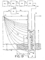
- Fig. 19 An embodiment of the invention is shown in Fig. 19 which allows measurement of the effect in cased holes. All of the numbered elements through element number 70 shown in Fig. 19 have already been defined in the description of Figs. 1 and 7.
- borehole casing 72 surrounds the borehole.
- a triggered single pulse 74 (abbreviated TSP) has been attached to the cable carrying the frequency marker output of the frequency sweep oscillator (70). The output of the TSP is attached to the reference input of the phase sensitive detector with cable 76. The purpose of the TSP is to make the response of the phase sensitive detector invariant to waveform changes from the marker output of the frequency sweep oscillator.
- a housing 78 surrounds the induction coil assembly.
- Electrode 30 is placed in contact with the casing above the induction coil gradiometer assembly in the embodiment shown in Fig. 19. Since the borehole casing is more conductive than the local formation, significant current l a is conducted downward along the casing before it is subsequently returned through the formation to electrode 52. This downward flowing current gives rise to an A.C. magnetic field on the exterior of the casing similar in nature to the A.C. magnetic field produced by an insulted cable in the open borehole case. Equation 12 describes the radial dependence of this A.C. magnetic field causing the excitation in formation. Furthermore, other excitation mechanisms dependent on the local conduction of the A.C. current may aid the excitation process and have already been described. Therefore, an excitation zone shown as the shaded region in Fig. 19 may be defined in the presence of the borehole casing.
- the PLE causes an amplitude modulation in the earth's magnetic field at the repetition rate.
- Low-frequency A.C. magnetic fields parallel to a long steel pipe are not affected dramatically by the presence of the pipe. Magnetic fields perpendicular to the steel pipe are, of course, dramatically shielded. Therefore, as long as there is a component of the magnetic field variation along the long axis of the borehole casing, the PLE can be measured through the casing. This question has been experimentally investigated as well.
- a 95 inch long, 11 7/8 inch I.D. air core solenoid was constructed to test the attenuation of longitudinal A.C. magnetic fields applied to an 85 inch long length of 9 5/8 inch O.D. type P-110 borehole casing (0.475 inch wall thickness, manufactured by Nippon Steel, Inc., and provided by Pipe Consultants, Inc., in Houston, Texas).
- the A.C. magnetic field inside the casing was measured with an air core induction coil.
- the attenuation factor 71 ( ⁇ Bpp in casing]/ ⁇ Bpp no casing ⁇ ) is plotted versus frequency in Fig. 20. Below 3 Hz the attenuation is less than 25%, and below 10 Hz the attenuation is below 50%.
- the presence of the borehole casing may dramatically improve the performance of the induction coil gradiometer.
- the magnetic field is caused to become nearly parallel to the axis of the induction coil gradiometer. Therefore, spurious induced voltages due to small angular movements of the induction coil would vary as the square of the angular movement as opposed to a linear dependence if the magnetic field were instead at a large angle with respect to the induction coil gradiometer.
- the housing surrounding the induction coil itself may intentionally be constructed from high permeability materials to help reduce spurious voltages induced in the coil due to small angular movements of the induction coil gradiometer. Therefore, the housing 78 surrounding the induction coil may intentionally be'fabricated from high permeability material.
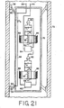
- Figure 21 shows features of a practical borehole tool used to measure the Paramagnetic Logging Effect inside a well bore which has been reinforced with borehole casing 72.
- windings 38 and 56 surrounding high permeability materials 40 and 58 respectively comprise the two induction coils.
- the capacitors C, and C2 tune the induction coils for parallel resonance, and resistors R, and R 2 make the Q's of the induction coils identical.
- the minimum contents of the ancillary instrumentation package 62 have already been described.
- the outer case of the borehole tool is 78.
- voltage amplifiers 80 and 82 provide signals to the signal processing instrumentation package 84 in the sonde.
- the signal processing instrumentation includes a means to adjust relative phase differences and gains between the two induction coils and also subtracts to the signals from the two coils.
- the differential output- is provided to the phase sensitive detector in Fig. 19 by cable 44.
- This cable is a multipleconductor cable as is widely used in borehole environments and can support a number of data paths which also allows analogue communication with the surface.
- bidirectional digital transmission devices could equally be included-in the processing instrumentation. If the measured signal is digitized, then this digital signal could be properly analyzed by a computer on the surface instead of the analogue phase sensitive detector shown in Fig. 19. This is certainly a minor variation of the invention as any phase sensitive instrumentation technique, analogue or digital, may be used to measure the PLE.
- high permeability material may be chosen to surround the induction coil to reduce the influence of motion on the output of the gradiometer.
- One of several cylindrical structures labeled as 86 in Fig. 21 could therefore be constructed from high permeability material.
- the high permeability material may also be used to reduce the production of eddy currents in the casing which would decrease the sensitivity of the induction coils. This reduction of eddy currents occurs because the magnetic flux lines which would normally radiate out of the high permeability cores 40 and 58 passing through the borehole casing 72 become instead trapped inside the borehole casing and pass through the high permeability material 86. That material may itself be slotted along its length to further reduce eddy current losses.
- the high permeability material may itself be fabricated from a large number of thin sheets of material which are electrically insulted from one another.
- the solenoids are used to balance the gradiometer by applying a known A.C. magnetic field at the detection frequency and balancing for null.
- the solenoids could also be used to apply a separate static magnetic field along the direction of the borehole to the formation. This action would artificially enhance the magnetization of the formation in the direction of the earth's magnetic field and this magnetization could be caused to be disrupted by application of a suitably frequency-swept A.C. magnetic field in the usual experimental measurement of the PLE. As this is an obvious extension of the present invention, no further details of this method of measurement will be described.
- a mechanical arm 90, attached to the sonde, has a conducting pad 92 which is held in contact with the borehole casing by usual methods in the industry. Such a mechanism serves to center the sonde, prevent vibrations since slack can be introduced into the cables 28 and 44 supporting the weight of the sonde, and also serves to introduce the frequency-swept A.C. current onto the casing via cable 28. Cable 28 is attached to the conducting pad 92 which is otherwise insulted from the sonde and this pad, or electrode, provides the majority of the A.C. current causing excitation in the formation.
- mechanical arm 94 is also attached to the-sonde and supports another conducting pad 96 which makes contact with the casing.
- Current is provided to this conducting pad through R, which is a resistor in series with cable 28.
- the insulted cable 98 consequently carries a relatively small A.C. current, and the frequency-swept A.C. magnetic field generated by this wire causes only fluids in the borehole to be continually excited as previously described and therefore prevents signals from borehole fluids to confuse interpretation of the measurements from the sonde.
- Other combinations of conducting pads, extra solenoids, and extra A.C. current-carrying cables can be used for analogous purposes and are obvious extensions of the present invention.
- induction coils within the sonde.
- These induction coils could work in unison in a variety of ways to produce the effects desired from a simple two-coil gradiometer and would help to eliminate spurious effects on the data by variable wall thickness of the borehole casing.
- the addition of such extra induction coils to the sonde are minor variations of the present invention.
- any number of magnetometers of any type could be incorporated within the differential magnetometer assembly to accomplish the measurement tasks.
- outside housing of the sonde 78 may be fabricated from laminations of fiberglass and concentric stainless steel cylinders which have been slotted along their length. Such construction would have strength against pressure and would minimize eddy current losses.
- the presence of the borehole casing may aid measurement of the PLE in other ways.
- the current l a in Fig. 19 flows on the outside of the borehole casing and therefore produces little A.C. magnetic field inside the casing. Therefore, spurious signals induced in the induction coil gradiometer due to the A.C. magnetic field caused by flowing A.C. currents may be minimized by the presence of the casing.
- the borehole casing distorts the field strength of the ambient earth's magnetic field. Therefore, there will be a predictable frequency causing resonance at a given radial distance from the borehole casing. Therefore, frequency sweep intervals may be chosen to cause a number of different excitation geometries surrounding the borehole.
- toroidal excitation regions around the borehole casing may be produced by judiciously selecting the frequency sweep interval.
- the presence of the borehole casing provides a firm surface which may be used to firmly lock the borehole tool in place, thereby preventing swaying motion of the gradiometer.
- the major problems in measuring the PLE are expected to be minimizing environmental disturbances within the synchronous detection bandwidth. Such problems include microphonics of the gradiometer which can be minimized by isolating the gradiometer from vibrations and minimizing stresses on the high permeability cores inside the induction coils. Furthermore, temperature stabilization of the induction coils within the gradiometers may ultimately prove to be important to minimize such stresses. Ultimately, the fiberoptic magnetometers which have already been briefly described may eventually prove to be superior in measuring the PLE as these instruments are not as sensitive to vibrations as are the induction coil gradiometers.
- FIG. 22 Another embodiment of the invention is shown in Figure 22. This embodiment is appropriate where no drill-hole has been drilled anywhere in ⁇ the vicinity of the oil deposit. All of the numbered elements have already been described in Figure 19.
- A.C. current is passed through the formation between electrodes 52 and 30 which is repetitively frequency swept through the Larmor frequency of the nucleons in the oil reservoir. This frequency swept A.C. - current provides a repetitively frequency-swept A.C. magnetic field which must be sufficient in magnitude to cause excitation within the shaded region of the formation in Figure 22.
- the PLE results in the amplitude modulation of the earth's magnetic field in the vicinity of the petroleum reservoir.
- the amplitude modulation of the earth's magnetic field above the oil reservoir on the earth's surface is sensed with an induction coil gradiometer, where the two induction coils are configured as shown in Figure 22.
- the induction coil vertically over the oil deposit comprising windings 38 and high permeability material 40 senses the amplitude modulation of the earth's magnetic field caused by the repetitive excitation of the oil bearing formation.
- Another induction coil located a distance H from the first induction coil comprising windings 56 and high-permeability material 58 is used to subtract common-mode fluctuations in the earth's magnetic field measured by both induction coils in the usual manner already described.
- the differential output of the gradiometer is provided by subtracting the individual outputs of the induction coils using differential amplifier 60.
- D the depth of investigation
- the effective depth of investigation will also be limited by the sensitivity of the induction coils. These surface mounted induction coils could also, obviously, be replaced with any magnetic field sensing element such as squids, or large air core induction coils with many turns, and a diameter of one mile or more. Furthermore, A.C.
- a wire could be used to connect electrodes 52 and 30 directly together which has many turns forming a very large diameter coil on the surface of the earth which could also provide the necessary A.C. magnetic field to cause the excitation of the formation.
- Any means may be used to cause the oil bearing formation to pass through the condition of nuclear magnetic resonance. Consequently, any means may be used to apply an A.C. magnetic field to the oil bearing formation near the Larmor frequency.
- Different methods of applying this A.C. magnetic field to the oil strata include but are not limited to the following: (1) passing A.C current through the formation from one or more boreholes to one or more surface electrodes; (2) passing A.C. current between two or more boreholes; (3) passing A.C. current through the earth between two or more electrodes placed on the earth's surface; (4) using one or more A.C. current-carrying circular loops on the surface of the earth; (5) using one or more rectangular shaped A.C. current-carrying coils on the surface of the earth; (6) inducing an A.C. magnetic field in the pipe surrounding a borehole with A.C. current-carrying coils on the surface of the earth; (7) inducing an A.C.
- the invention explicitly exploits the properties of nuclear magnetic moments such as unpaired protons.
- the method and apparatus can be applied to other nuclear, electronic, atomic, or molecular properties of petroleum which have similar gyromagnetic features.
- impurities in petroleum and connate water evaluations of World's Important Crudes, 1973, and A Guide to World Export Crudes, 1976, both published by The Petroleum Publishing Company, P.O. Box 1260, Tulsa, Oklahoma; W. Duchscherer, Jr., Geochemical H y drocar- bon Prospecting with Case Histories, Penwell Books, Tulsa, Oklahoma, 1984; and V.
- Electronic paramagnetism may be caused by atoms and molecules possessing an odd number of electrons, free atoms and ions with partially filled inner shells, ionic compounds of all varieties, rare earth and actinide elements, several compounds with an even number of electrons, organic biradicals, and many metals - (C. Kittel, op. cit.). Many of these compounds have "unpaired" electrons which have electronic magnetic moments which cause the electronic paramagnetism. Therefore, it is expected that a large number of impurities in crude petroleum will exhibit the phenomenon of electronic paramagnetism. The electron's magnetic moment is some 658 times stronger than the magnetic moment of the proton, and therefore minute concentrations of electronic paramagnetic impurities would give rise to measurable paramagnetic effects.
- the apparatus shown in Figs. 1, 7, 19, and 21 are employed to measure the presence of such electronic paramagnetic impurities provided the frequency of the A.C. magnetic field applied to the excitation zone of the formation is appropriate for the Larmor frequency of the electronic paramagnetic substances in formation.
- the frequency for single electronic paramagnetic substances is approximately 1.4 megahertz in the earth's magnetic field of approximately 0.5 gauss. Therefore, periodically sweeping the electronic paramagnetic substances through a state of electronic paramagnetic resonance would periodically disrupt the paramagnetism within the excitation zone of the formation. This periodic disruption of the paramagnetism in the formation would result in the amplitude modulation of the earth's magnetic field in the vicinity of the excitation zone.
- the amplitude of the modulation of the earth's magnetic field would indicate the presence or absence of electronic paramagnetic impurities.
- the respective longitudinal relaxation times of the impurities measured by selectively changing the repetition rate would serve to specifically identify the chemical nature of the impurities.
- the presence of certain paramagnetic impurities would serve to indicate that certain formations contain petroleum and would provide information about the chemical nature of the reservoir.
- at least several varieties of paramagnetism may be present in formation simultaneously: nuclear paramagnetism, electronic paramagnetism, etc.
- any gyromagnetic substance simultaneously possessing both intrinsic angular momentum and an intrinsic magnetic moment exhibits the phenomenon of magnetic resonance and has a particular gyromagnetic ratio which results in a specific Larmor frequency appropriate for the gyromagnetic substance in the earth's magnetic field. That gyromagnetic substance would also necessarily exhibit the phenomenon of paramagnetism in the earth's magnetic field.
- Application of an A.C. magnetic field at the Larmor frequency appropriate for the gyromagnetic substance within an excitation zone of the formation containing that substance. This disruption of the , paramagnetism of the gyromagnetic substance within an excitation zone of the formation would result in a variation in the earth's magnetic field in the vicinity of the excitation zone.
- Repetitively frequency sweeping the A.C. magnetic field through the Larmor frequency of the gyromagnetic substance thereby repetitively placing a significant portion of the formation containing the gyromagnetic substance into a state of magnetic resonance would result in an amplitude modulation of the paramagnetism of the substance within the excitation zone of the formation.
- This modulation of the paramagnetism in turn would cause an amplitude modulation of the earth's magnetic field in the vicinity of the excitation zone of the formation.
- the amplitude of the modulation in the earth's magnetic field would serve to indicate the concentration of the gyromagnetic impurity present in the excitation zone of the formation.
- the measurement of the respective longitudinal relaxation times of the gyromagnetic substances by selectively varying the period of the repetition of the frequency sweeps through resonance would serve to specifically identify the gyromagnetic substances.
- the presence of a substance, or impurity, in the formation would serve to identify the chemical characteristics of the petroleum reservoir and locate unknown oil bearing formations as well.
Applications Claiming Priority (2)
| Application Number | Priority Date | Filing Date | Title |
|---|---|---|---|
| US06/720,943 US4656422A (en) | 1982-06-10 | 1985-04-08 | Oil well logging tools measuring paramagnetic logging effect for use in open boreholes and cased well bores |
| US720943 | 1985-04-08 |
Publications (2)
| Publication Number | Publication Date |
|---|---|
| EP0198638A2 true EP0198638A2 (de) | 1986-10-22 |
| EP0198638A3 EP0198638A3 (de) | 1989-03-29 |
Family
ID=24895878
Family Applications (1)
| Application Number | Title | Priority Date | Filing Date |
|---|---|---|---|
| EP86302525A Withdrawn EP0198638A3 (de) | 1985-04-08 | 1986-04-04 | Ölbohrlochmessgeräte zur Anwendung in offenen Bohrlöchern und in gekapselten Bohrsonden mittels Messung des paramagnetischen Effektes |
Country Status (4)
| Country | Link |
|---|---|
| US (1) | US4656422A (de) |
| EP (1) | EP0198638A3 (de) |
| JP (1) | JPS62889A (de) |
| CA (1) | CA1263440A (de) |
Cited By (3)
| Publication number | Priority date | Publication date | Assignee | Title |
|---|---|---|---|---|
| GB2211947A (en) * | 1987-11-05 | 1989-07-12 | Shell Int Research | Nuclear magnetism borehole logging tool |
| US5800417A (en) * | 1995-12-12 | 1998-09-01 | Goerg-Wood; Kristin Ann | Absorbent composition comprising hydrogel-forming polymeric material and fiber bundles |
| US6181132B1 (en) * | 1998-10-02 | 2001-01-30 | Shell Oil Company | NMR logging assembly |
Families Citing this family (34)
| Publication number | Priority date | Publication date | Assignee | Title |
|---|---|---|---|---|
| US4792757A (en) * | 1985-04-08 | 1988-12-20 | Paramagnetic Logging, Inc. | Oil well logging tools measuring paramagnetic logging effect for use in open boreholes and cased well bores |
| US4724385A (en) * | 1986-11-03 | 1988-02-09 | Paramagnetic Logging, Inc. | Acoustic paramagnetic logging tool |
| US5306640A (en) * | 1987-10-28 | 1994-04-26 | Shell Oil Company | Method for determining preselected properties of a crude oil |
| US4987368A (en) * | 1987-11-05 | 1991-01-22 | Shell Oil Company | Nuclear magnetism logging tool using high-temperature superconducting squid detectors |
| US5122746A (en) * | 1990-06-12 | 1992-06-16 | Gas Research Institute | Hydrocarbon gas measurements using nuclear magnetic resonance |
| US5189371A (en) * | 1991-08-08 | 1993-02-23 | The Board Of Trustees Of The Leland Stanford Junior University | Method and means for magnetic resonance imaging and spectroscopy using two-dimensional selective adiabatic PI pulses |
| EP0581666B1 (de) * | 1992-07-30 | 1997-10-01 | Schlumberger Limited | Gepulster NMR-Gerät zur Formationsbewertung während des Bohrens |
| US5923167A (en) * | 1992-07-30 | 1999-07-13 | Schlumberger Technology Corporation | Pulsed nuclear magnetism tool for formation evaluation while drilling |
| US5596274A (en) * | 1992-12-31 | 1997-01-21 | Schlumberger Technology Corporation | Determining bound and unbound fluid volumes using nuclear magnetic resonance pulse sequences |
| US6512371B2 (en) | 1995-10-12 | 2003-01-28 | Halliburton Energy Services, Inc. | System and method for determining oil, water and gas saturations for low-field gradient NMR logging tools |
| US6956371B2 (en) * | 1995-10-12 | 2005-10-18 | Halliburton Energy Services, Inc. | Method and apparatus for detecting diffusion sensitive phases with estimation of residual error in NMR logs |
| US6531868B2 (en) * | 1996-12-30 | 2003-03-11 | Halliburton Energy Services, Inc. | System and methods for formation evaluation while drilling |
| US6166543A (en) * | 1997-09-25 | 2000-12-26 | Schlumberger Technology Corporation | Method and apparatus for measuring nuclear magnetic resonance |
| US6133734A (en) * | 1997-12-30 | 2000-10-17 | Schlumberger Technology Corporation | Method and apparatus for evaluating an earth formation using nuclear magnetic resonance techiques |
| US6114972A (en) * | 1998-01-20 | 2000-09-05 | Halliburton Energy Services, Inc. | Electromagnetic resistivity tool and method for use of same |
| US6377042B1 (en) | 1998-08-31 | 2002-04-23 | Numar Corporation | Method and apparatus for merging of NMR echo trains in the time domain |
| US6366087B1 (en) | 1998-10-30 | 2002-04-02 | George Richard Coates | NMR logging apparatus and methods for fluid typing |
| AU3007300A (en) * | 1999-02-26 | 2000-09-14 | Purdue Research Foundation | Nuclear magnetic resonance analysis of multiple samples |
| US6661226B1 (en) | 1999-08-13 | 2003-12-09 | Halliburton Energy Services, Inc. | NMR apparatus and methods for measuring volumes of hydrocarbon gas and oil |
| US6255819B1 (en) | 1999-10-25 | 2001-07-03 | Halliburton Energy Services, Inc. | System and method for geologically-enhanced magnetic resonance imaging logs |
| US6445187B1 (en) | 2000-04-10 | 2002-09-03 | Jerry R. Montgomery | System for the measurement of electrical characteristics of geological formations from within steel cased wells using magnetic circuits |
| EP1642156B1 (de) * | 2003-05-02 | 2020-03-04 | Halliburton Energy Services, Inc. | Systeme und verfahren zum nmr-logging |
| US6938469B2 (en) * | 2003-08-06 | 2005-09-06 | Schlumberger Technology Corporation | Method for determining properties of formation fluids |
| GB2422201B (en) | 2003-10-03 | 2007-06-06 | Halliburton Energy Serv Inc | System And Methods For T1-Based Logging |
| WO2009041343A1 (ja) | 2007-09-25 | 2009-04-02 | Japan Oil, Gas And Metals National Corporation | 電磁探査装置および電磁探査方法 |
| US8330460B2 (en) * | 2008-01-30 | 2012-12-11 | Baker Hughes Incorporated | Method and apparatus for determining multiscale similarity between NMR measurements and a reference well log |
| US8646520B2 (en) * | 2011-03-15 | 2014-02-11 | Baker Hughes Incorporated | Precision marking of subsurface locations |
| JP2015014526A (ja) * | 2013-07-05 | 2015-01-22 | 独立行政法人石油天然ガス・金属鉱物資源機構 | 電磁探査方法 |
| US9952346B2 (en) * | 2013-11-26 | 2018-04-24 | Halliburton Energy Services, Inc. | Fiber optic magnetic field sensing system based on lorentz force method for downhole applications |
| US10114081B2 (en) * | 2014-08-08 | 2018-10-30 | Halliburton Energy Services, Inc. | Low-noise fluxgate magnetometer with increased operating temperature range |
| WO2018052449A1 (en) * | 2016-09-19 | 2018-03-22 | Halliburton Energy Services, Inc. | Method of detecting substance saturation in a formation |
| US10989646B1 (en) * | 2020-05-21 | 2021-04-27 | Halliburton Energy Services, Inc. | Real time magnetic properties of drill cuttings, drilling fluids, and soils |
| WO2023106418A1 (ja) * | 2021-12-09 | 2023-06-15 | 有限会社沖縄基礎開発 | 磁気探査システム |
| CN114961703B (zh) * | 2022-04-15 | 2023-01-20 | 中国石油天然气集团有限公司 | 一种水泥塞井眼的定位方法、装置、电子设备及存储介质 |
Citations (2)
| Publication number | Priority date | Publication date | Assignee | Title |
|---|---|---|---|---|
| US2984781A (en) * | 1953-03-09 | 1961-05-16 | Schlumberger Well Surv Corp | Apparatus for the nondestructive testing of materials |
| EP0190481A1 (de) * | 1982-06-10 | 1986-08-13 | William Banning Vail, III | Kernmagnetisches Resonanzverfahren und Einrichtung für entfernte Detektion und volumetrische Messung von Erdölreserven |
Family Cites Families (3)
| Publication number | Priority date | Publication date | Assignee | Title |
|---|---|---|---|---|
| US3060371A (en) * | 1955-07-20 | 1962-10-23 | Townsend Jonathan | Geological prospecting process and apparatus |
| US3360716A (en) * | 1956-08-06 | 1967-12-26 | Varian Associates | Gyromagnetic resonance methods and apparatus |
| US3213357A (en) * | 1962-10-22 | 1965-10-19 | California Research Corp | Earth formation and fluid material investigation by nuclear magnetism relaxation rate determination |
-
1985
- 1985-04-08 US US06/720,943 patent/US4656422A/en not_active Expired - Lifetime
-
1986
- 1986-04-04 EP EP86302525A patent/EP0198638A3/de not_active Withdrawn
- 1986-04-04 CA CA000505850A patent/CA1263440A/en not_active Expired
- 1986-04-08 JP JP61080945A patent/JPS62889A/ja active Pending
Patent Citations (2)
| Publication number | Priority date | Publication date | Assignee | Title |
|---|---|---|---|---|
| US2984781A (en) * | 1953-03-09 | 1961-05-16 | Schlumberger Well Surv Corp | Apparatus for the nondestructive testing of materials |
| EP0190481A1 (de) * | 1982-06-10 | 1986-08-13 | William Banning Vail, III | Kernmagnetisches Resonanzverfahren und Einrichtung für entfernte Detektion und volumetrische Messung von Erdölreserven |
Cited By (4)
| Publication number | Priority date | Publication date | Assignee | Title |
|---|---|---|---|---|
| GB2211947A (en) * | 1987-11-05 | 1989-07-12 | Shell Int Research | Nuclear magnetism borehole logging tool |
| GB2211947B (en) * | 1987-11-05 | 1992-07-08 | Shell Int Research | Nuclear magnetism logging tool using high-temperature superconducting squid detectors |
| US5800417A (en) * | 1995-12-12 | 1998-09-01 | Goerg-Wood; Kristin Ann | Absorbent composition comprising hydrogel-forming polymeric material and fiber bundles |
| US6181132B1 (en) * | 1998-10-02 | 2001-01-30 | Shell Oil Company | NMR logging assembly |
Also Published As
| Publication number | Publication date |
|---|---|
| US4656422A (en) | 1987-04-07 |
| CA1263440A (en) | 1989-11-28 |
| JPS62889A (ja) | 1987-01-06 |
| EP0198638A3 (de) | 1989-03-29 |
Similar Documents
| Publication | Publication Date | Title |
|---|---|---|
| US4656422A (en) | Oil well logging tools measuring paramagnetic logging effect for use in open boreholes and cased well bores | |
| US4792757A (en) | Oil well logging tools measuring paramagnetic logging effect for use in open boreholes and cased well bores | |
| US4528508A (en) | Nuclear magnetic resonance method and apparatus for remote detection and volumetric measurement of petroleum reserves | |
| US5796252A (en) | Nuclear magnetic resonance borehole logging apparatus and method for ascertaining a volume of hydrocarbons independent of a diffusion coefficient | |
| US5260661A (en) | Calibrating and compensating influence of casing thickness variations on measurements of low frequency A.C. magnetic fields within cased boreholes to determine properties of geological formations | |
| US5680043A (en) | Nuclear magnetic resonance technique for determining gas effect with borehole logging tools | |
| EP0459064B1 (de) | Bohrlochmessung von NMR-Charakteristika von Erdformationen und Interpretation davon | |
| US9335195B2 (en) | Multiphase meter to provide data for production management | |
| US6342784B1 (en) | Method for resistivity well logging utilizing nuclear magnetic resonance | |
| US9645277B2 (en) | Estimating molecular size distributions in formation fluid samples using a downhole NMR fluid analyzer | |
| US6400148B1 (en) | Use of redundant data for log quality measurements | |
| AU2014364155B2 (en) | Method of interpreting NMR signals to give multiphase fluid flow measurements for a gas/liquid system | |
| CA2230908C (en) | Longitudinal nmr well logging apparatus and method | |
| US5065100A (en) | Measurement of in-phase and out-of-phase components of low frequency A.C. magnetic fields within cased boreholes to measure geophysical properties of geological formations | |
| US6177794B1 (en) | Use of earth field spin echo NMR to search for liquid minerals | |
| Jackson | Nuclear magnetic resonance well logging | |
| US20160305239A1 (en) | Downhole monitoring of fluids using nuclear magnetic resonance | |
| Shi et al. | A proposed NMR solution for multi-phase flow fluid detection | |
| US2984781A (en) | Apparatus for the nondestructive testing of materials | |
| Vasić et al. | Scaled experimental verification of single-well induction conductivity measurement through nonmagnetic casing | |
| US6563314B1 (en) | Well logging method and apparatus for determining the nuclear magnetic resonance longitudinal magnetization decay of formations | |
| US3213354A (en) | Nuclear precession well logging apparatus | |
| Kickhofel et al. | Inductive conductivity tensor measurement for flowline or material samples | |
| CA1217814A (en) | Nuclear magnetic resonance method and apparatus for remote detection and volumetric measurement of petroleum reserves | |
| Goswami et al. | On the design of NMR sensor for well-logging applications |
Legal Events
| Date | Code | Title | Description |
|---|---|---|---|
| PUAI | Public reference made under article 153(3) epc to a published international application that has entered the european phase |
Free format text: ORIGINAL CODE: 0009012 |
|
| AK | Designated contracting states |
Kind code of ref document: A2 Designated state(s): AT BE CH DE FR GB IT LI LU NL SE |
|
| PUAL | Search report despatched |
Free format text: ORIGINAL CODE: 0009013 |
|
| AK | Designated contracting states |
Kind code of ref document: A3 Designated state(s): AT BE CH DE FR GB IT LI LU NL SE |
|
| STAA | Information on the status of an ep patent application or granted ep patent |
Free format text: STATUS: THE APPLICATION IS DEEMED TO BE WITHDRAWN |
|
| 18D | Application deemed to be withdrawn |
Effective date: 19890930 |
|
| RIN1 | Information on inventor provided before grant (corrected) |
Inventor name: SCHWINBERG, PAUL B. Inventor name: VAIL III, WILLIAM BANNING |