EP0198627A1 - Improvements in or relating to the manufacture of rotary drill bits - Google Patents
Improvements in or relating to the manufacture of rotary drill bits Download PDFInfo
- Publication number
- EP0198627A1 EP0198627A1 EP86302376A EP86302376A EP0198627A1 EP 0198627 A1 EP0198627 A1 EP 0198627A1 EP 86302376 A EP86302376 A EP 86302376A EP 86302376 A EP86302376 A EP 86302376A EP 0198627 A1 EP0198627 A1 EP 0198627A1
- Authority
- EP
- European Patent Office
- Prior art keywords
- alloy
- phosphorus
- mould
- copper
- infiltration
- Prior art date
- Legal status (The legal status is an assumption and is not a legal conclusion. Google has not performed a legal analysis and makes no representation as to the accuracy of the status listed.)
- Granted
Links
- 238000004519 manufacturing process Methods 0.000 title claims abstract description 8
- 229910045601 alloy Inorganic materials 0.000 claims abstract description 36
- 239000000956 alloy Substances 0.000 claims abstract description 36
- 239000011159 matrix material Substances 0.000 claims abstract description 32
- 230000008595 infiltration Effects 0.000 claims abstract description 27
- 238000001764 infiltration Methods 0.000 claims abstract description 27
- RYGMFSIKBFXOCR-UHFFFAOYSA-N Copper Chemical compound [Cu] RYGMFSIKBFXOCR-UHFFFAOYSA-N 0.000 claims abstract description 13
- OAICVXFJPJFONN-UHFFFAOYSA-N Phosphorus Chemical compound [P] OAICVXFJPJFONN-UHFFFAOYSA-N 0.000 claims abstract description 13
- 229910052802 copper Inorganic materials 0.000 claims abstract description 13
- 239000010949 copper Substances 0.000 claims abstract description 13
- 229910052698 phosphorus Inorganic materials 0.000 claims abstract description 13
- 239000011574 phosphorus Substances 0.000 claims abstract description 13
- 239000000463 material Substances 0.000 claims abstract description 10
- 229910001092 metal group alloy Inorganic materials 0.000 claims abstract description 4
- 238000012856 packing Methods 0.000 claims abstract description 4
- 238000000465 moulding Methods 0.000 claims abstract description 3
- 238000005520 cutting process Methods 0.000 claims description 34
- 238000000034 method Methods 0.000 claims description 26
- 229910000831 Steel Inorganic materials 0.000 claims description 19
- 239000010959 steel Substances 0.000 claims description 19
- 229910052709 silver Inorganic materials 0.000 claims description 8
- 239000004332 silver Substances 0.000 claims description 8
- 229910052739 hydrogen Inorganic materials 0.000 claims description 4
- 239000001257 hydrogen Substances 0.000 claims description 4
- UFHFLCQGNIYNRP-UHFFFAOYSA-N Hydrogen Chemical compound [H][H] UFHFLCQGNIYNRP-UHFFFAOYSA-N 0.000 claims description 3
- 229910001096 P alloy Inorganic materials 0.000 claims description 3
- 229910001128 Sn alloy Inorganic materials 0.000 claims description 3
- ATJFFYVFTNAWJD-UHFFFAOYSA-N Tin Chemical compound [Sn] ATJFFYVFTNAWJD-UHFFFAOYSA-N 0.000 claims description 3
- FEEABVAOCDUXPH-UHFFFAOYSA-N [Ag].[P].[Cu] Chemical compound [Ag].[P].[Cu] FEEABVAOCDUXPH-UHFFFAOYSA-N 0.000 claims description 3
- RIRXDDRGHVUXNJ-UHFFFAOYSA-N [Cu].[P] Chemical compound [Cu].[P] RIRXDDRGHVUXNJ-UHFFFAOYSA-N 0.000 claims description 3
- YWIHFOITAUYZBJ-UHFFFAOYSA-N [P].[Cu].[Sn] Chemical compound [P].[Cu].[Sn] YWIHFOITAUYZBJ-UHFFFAOYSA-N 0.000 claims description 3
- 230000005496 eutectics Effects 0.000 claims description 3
- 239000000203 mixture Substances 0.000 claims description 3
- 229910001316 Ag alloy Inorganic materials 0.000 claims description 2
- 230000015572 biosynthetic process Effects 0.000 description 8
- 238000005755 formation reaction Methods 0.000 description 8
- 238000005553 drilling Methods 0.000 description 4
- 229910003460 diamond Inorganic materials 0.000 description 3
- 239000010432 diamond Substances 0.000 description 3
- 230000008646 thermal stress Effects 0.000 description 3
- OKTJSMMVPCPJKN-UHFFFAOYSA-N Carbon Chemical compound [C] OKTJSMMVPCPJKN-UHFFFAOYSA-N 0.000 description 2
- 230000006378 damage Effects 0.000 description 2
- 239000012530 fluid Substances 0.000 description 2
- 229910002804 graphite Inorganic materials 0.000 description 2
- 239000010439 graphite Substances 0.000 description 2
- 238000003754 machining Methods 0.000 description 2
- 239000000843 powder Substances 0.000 description 2
- 238000004663 powder metallurgy Methods 0.000 description 2
- UONOETXJSWQNOL-UHFFFAOYSA-N tungsten carbide Chemical compound [W+]#[C-] UONOETXJSWQNOL-UHFFFAOYSA-N 0.000 description 2
- 229910000881 Cu alloy Inorganic materials 0.000 description 1
- HCHKCACWOHOZIP-UHFFFAOYSA-N Zinc Chemical compound [Zn] HCHKCACWOHOZIP-UHFFFAOYSA-N 0.000 description 1
- 238000000429 assembly Methods 0.000 description 1
- 230000000712 assembly Effects 0.000 description 1
- 229910052793 cadmium Inorganic materials 0.000 description 1
- BDOSMKKIYDKNTQ-UHFFFAOYSA-N cadmium atom Chemical compound [Cd] BDOSMKKIYDKNTQ-UHFFFAOYSA-N 0.000 description 1
- 229910052799 carbon Inorganic materials 0.000 description 1
- 239000000969 carrier Substances 0.000 description 1
- 230000001010 compromised effect Effects 0.000 description 1
- 238000001816 cooling Methods 0.000 description 1
- 238000005336 cracking Methods 0.000 description 1
- 230000002939 deleterious effect Effects 0.000 description 1
- 230000006866 deterioration Effects 0.000 description 1
- 150000002431 hydrogen Chemical class 0.000 description 1
- 238000003780 insertion Methods 0.000 description 1
- 230000037431 insertion Effects 0.000 description 1
- 229910052751 metal Inorganic materials 0.000 description 1
- 239000002184 metal Substances 0.000 description 1
- 239000012254 powdered material Substances 0.000 description 1
- 238000004901 spalling Methods 0.000 description 1
- 230000035882 stress Effects 0.000 description 1
- 230000003685 thermal hair damage Effects 0.000 description 1
- WFKWXMTUELFFGS-UHFFFAOYSA-N tungsten Chemical compound [W] WFKWXMTUELFFGS-UHFFFAOYSA-N 0.000 description 1
- 229910052721 tungsten Inorganic materials 0.000 description 1
- 239000010937 tungsten Substances 0.000 description 1
- 229910052725 zinc Inorganic materials 0.000 description 1
- 239000011701 zinc Substances 0.000 description 1
Images
Classifications
-
- E—FIXED CONSTRUCTIONS
- E21—EARTH OR ROCK DRILLING; MINING
- E21B—EARTH OR ROCK DRILLING; OBTAINING OIL, GAS, WATER, SOLUBLE OR MELTABLE MATERIALS OR A SLURRY OF MINERALS FROM WELLS
- E21B10/00—Drill bits
- E21B10/46—Drill bits characterised by wear resisting parts, e.g. diamond inserts
-
- B—PERFORMING OPERATIONS; TRANSPORTING
- B22—CASTING; POWDER METALLURGY
- B22F—WORKING METALLIC POWDER; MANUFACTURE OF ARTICLES FROM METALLIC POWDER; MAKING METALLIC POWDER; APPARATUS OR DEVICES SPECIALLY ADAPTED FOR METALLIC POWDER
- B22F3/00—Manufacture of workpieces or articles from metallic powder characterised by the manner of compacting or sintering; Apparatus specially adapted therefor ; Presses and furnaces
- B22F3/24—After-treatment of workpieces or articles
- B22F3/26—Impregnating
-
- B—PERFORMING OPERATIONS; TRANSPORTING
- B22—CASTING; POWDER METALLURGY
- B22F—WORKING METALLIC POWDER; MANUFACTURE OF ARTICLES FROM METALLIC POWDER; MAKING METALLIC POWDER; APPARATUS OR DEVICES SPECIALLY ADAPTED FOR METALLIC POWDER
- B22F7/00—Manufacture of composite layers, workpieces, or articles, comprising metallic powder, by sintering the powder, with or without compacting wherein at least one part is obtained by sintering or compression
- B22F7/06—Manufacture of composite layers, workpieces, or articles, comprising metallic powder, by sintering the powder, with or without compacting wherein at least one part is obtained by sintering or compression of composite workpieces or articles from parts, e.g. to form tipped tools
-
- C—CHEMISTRY; METALLURGY
- C22—METALLURGY; FERROUS OR NON-FERROUS ALLOYS; TREATMENT OF ALLOYS OR NON-FERROUS METALS
- C22C—ALLOYS
- C22C1/00—Making non-ferrous alloys
- C22C1/04—Making non-ferrous alloys by powder metallurgy
- C22C1/0475—Impregnated alloys
Definitions
- the comparatively low infiltration temperature according to the invention has the advantage that conventional preforms of the kind first described above may withstand the furnace temperature and may thus be located in the mould and incorporated in the bit body during formation of the matrix. Furthermore, the steel blank which is first introduced into the mould may be a one-piece element which may also be pre-machined to provide the threaded shank on the finished drill bit. Both these advantages may reduce significantly the cost of manufacture of the bit.
- the filled mould is placed in a furnace and heated to cause the alloy to fuse and infiltrate the matrix forming material in known manner. It has been found preferable to carry out the infiltration in the furnace in an atmosphere of dry hydrogen, for example hydrogen having a dew point of approximately -30°C. Alternatively, the infiltration may be carried out in a vacuum furnace.
Landscapes
- Engineering & Computer Science (AREA)
- Mechanical Engineering (AREA)
- Chemical & Material Sciences (AREA)
- Manufacturing & Machinery (AREA)
- Life Sciences & Earth Sciences (AREA)
- Materials Engineering (AREA)
- Geology (AREA)
- Mining & Mineral Resources (AREA)
- General Life Sciences & Earth Sciences (AREA)
- Geochemistry & Mineralogy (AREA)
- Fluid Mechanics (AREA)
- Environmental & Geological Engineering (AREA)
- Metallurgy (AREA)
- Organic Chemistry (AREA)
- Physics & Mathematics (AREA)
- Composite Materials (AREA)
- Earth Drilling (AREA)
Abstract
Description
- The invention relates to rotary drill bits for use in drilling or coring deep holes in subsurface formations.
- In particular, the invention is applicable to rotary drill bits of the kind comprising a bit body having an external surface on which are mounted a plurality of cutting elements for cutting or abrading the formation, and an inner passage for supplying drilling fluid to one or more nozzles at the external surface of the bit. The nozzles are so located at the surface of the bit body that drilling fluid emerging from the nozzles flows past the cutting elements, during drilling, so as to cool and/or clean them.
- Although not essential to the present invention, the cutting elements may be in the form of so-called "preform" cutting elements in the shape of a tablet, often circular, having a superhard cutting face formed of polycrystalline diamond or other superhard material.
- In one commonly used method of making rotary . drill bits of the above mentioned type, the bit body is formed by a powder metallurgy process. In this process a hollow mould is first formed, for example from graphite, in the configuration of the bit body or a part thereof. The mould is packed with powdered material, such as tungsten carbide, which is then infiltrated with a metal alloy, such as a copper alloy, in a furnace so as to form a hard matrix.
- Using conventional infiltration alloys, the furnace temperature required to form the matrix is usually of the order of 1000° C to 1170° C and this leads to certain disadvantages. For example, conventional polycrystalline diamond preforms are only thermally stable up to a temperature of 700° - 750° C. For this reason the preform cutting elements, or cutting structures incorporating the elements, are normally mounted in the bit body- after it has been infiltrated. The interior surface of the mould is therefore normally suitably shaped to provide surfaces to which the cutting elements may be subsequently brazed, or to provide sockets to receive studs or carriers to which the cutting elements are bonded. The subsequent mounting of the cutting elements on the body is a time-consuming and costly process, and may involve serious technical difficulties. The cutting elements and/or cutting structures must also be made sufficiently accurately to fit the pockets in the bit body, and this also adds to the cost.
- There are now available certain polycrystalline diamond preforms which are thermally stable up to conventional infiltration temperatures, typically about 1100° C. However, the use of such thermally stable preforms gives rise to further problems, particularly wiht regard to ensuring that the cutting elements are securely mounted on the bit body with sufficient exposure for optimum cutting action.
- Conventionally, before the matrix is formed, the mould is partly filled with a steel blank, the matrix being formed around the blank. After the matrix forming process, a further steel piece is welded onto a projecting portion of the blank and is shaped and formed with a thread to provide the-threaded shank by means of which the drill bit may be connected to the drill string. The provision of the threaded shank must be effected after the matrix has been formed since the high infiltration temperature can cause metallurgical deterioration of the steel blank.
- In order to avoid the above mentioned disadvantages, it has been proposed to use a low temperature infiltration alloy such that the infiltration temperature is below about 700° C, i.e. is at a temperature where conventional preforms are thermally stable. One such low temperature alloy has comprised 45% silver, 15% copper, 16% zinc and 24% cadmium. However, the use of such alloy has not proved commercially acceptable, not least because of its high cost.
- The present invention therefore sets out to provide a method of making a drill bit using a low temperature infiltrant which may overcome the disadvantages of the-known methods referred to above.
- According to the invention there is provided a method of making a rotary drill bit of the first-mentioned type by a powder metallurgy process, the method comprising forming a hollow mould for moulding at least a portion of the bit body, packing at least part of the mould with powdered matrix material, and infiltrating the material with a metal alloy in a furnace to form a matrix, the alloy being a copper based alloy containing phosphorus and being selected to provide an infiltration temperature - which is not greater than 850° C. Preferably the infiltration temperature is not greater than 750° C.
- The comparatively low infiltration temperature according to the invention has the advantage that conventional preforms of the kind first described above may withstand the furnace temperature and may thus be located in the mould and incorporated in the bit body during formation of the matrix. Furthermore, the steel blank which is first introduced into the mould may be a one-piece element which may also be pre-machined to provide the threaded shank on the finished drill bit. Both these advantages may reduce significantly the cost of manufacture of the bit.
- Although, as previously mentioned, thermally stable preforms may, in any case, be positioned in the mould at normal infiltration temperatures (11000 C - 1170° C), the method of the present invention may also be used advantageously with such thermally stable preforms. This is because, at the lower infiltration temperature according to the present invention, the difference in coefficient of thermal expansion between the preforms and the matrix material has less deleterious effect than it does at higher temperatures. Thus, using the lower temperature method of the invention, the preform cutting elements may be more securely embedded in the matrix material owing to less stress occurring at the interface between the materials during cooling of the bit body from the infiltration temperature.
- In the method according to the invention the alloy may be an essentially two-element copper-phosphorus alloy. The alloy may be of eutectic, or near-eutectic composition. For example, the alloy may comprise approximately 8.4% phosphorus in a copper base.
- In a further alternative the infiltration alloy may be a copper-phosphorus-tin alloy. For example, the alloy may comprise approximately 85% copper, up to 10% tin and up to 10% phosphorus.
- Another form of low temperature infiltration alloy which may be used in the invention is a copper-phosphorus-silver aloy having a copper base, up to 8% of phosphorus and up to 20% of silver. However, the proportion of silver in the alloy is preferably something of the order of 2% in view of the high cost of silver.
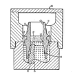
- The single figure is a diagrammatic vertical section through a mould showing the manufacture of a drill bit by the method according to the invention.
- Referring to the drawing, a two-part mould 10 is formed from graphite or other suitable material and has an internal configuration corresponding generally to the required surface shape of the bit body or a portion thereof. For example, the mould may be formed with elongate recesses to provide radially extending blades upstanding from the surface of the finished bit. In the case where cutting elements are to be incorporated in the bit body during formation thereof, the internal surface of the mould may also be shaped to provide locations to receive the cutting elements, or cutting structures incorporating such cutting elements. The cutting elements or structures may, for example, be glued in position on the internal surface of the mould.
- Alternatively, in the case where the cutting elements or cutting structures are to be mounted on the bit body after formation thereof, the surface of the mould may be formed with a plurality of sockets each of which receives a former, which formers, during formation of the matrix, define in the matrix sockets to receive the cutting elements or structures, such as studs, on which the cutting elements are mounted.
- The matrix material is moulded on and within a hollow steel blank 11. The steel blank is supported in the mould 10 so that its outer surface is spaced from the inner surface of the mould. The blank has an upper cylindrical internal cavity 12 communicating with a lower diverging
cavity 13. The upper portion of the blank 11 is formed with a machinedexternal screw thread 14 which will form the threaded shank for connecting the drill bit to the drill string. - There is also provided in the mould 10, at each desired location for a nozzle in the finished bit, a
socket 15 which receives one end of an elongate stepped cylindrical nozzle former 16 which extends into the mould space within thelower cavity 13 in the hollow steel blank 11. - After the insertion of the steel blank 11 into the mould, powdered matrix forming material (for example, powdered tungsten carbide) is packed around the outside of the steel blank and within the lower diverging
cavity 13 of the blank, and around theformers 16 and the formers or cutting elements mounted over the internal surface of the mould. Tungsten metal powder is then packed in part of the upper cavity 12 in the steel blank 11. - A body of infiltrant alloy is then located, as indicated at 17, above the matrix forming material both within and around the steel blank 11. In accordance with the invention, the alloy is a copper-based alloy containing phosphorus and is selected to provide an infiltration temperature which is not greater than 850° C and is preferably not greater than 750° C.
- A suitable alloy is a two-element copper-phosphorus alloy which is of eutectic or near-eutectic composition. For example the alloy may comprise approximately 8.4% phosphorus in a copper base..
- Another suitable form of alloy is a copper-phosphorus-tin alloy, for example comprising approximately 85% copper, up to 10% tin and up to 10% phosphorus.
- Another form of low temperature infiltration alloy which is suitable is a copper-phosphorus-silver alloy having a copper base, up to 8% of phosphorus and up to 20% of silver. Preferably however the proportion of silver is of the order of 2% to reduce cost.
- After the matrix forming material and infiltrant have been packed into the mould, the filled mould is placed in a furnace and heated to cause the alloy to fuse and infiltrate the matrix forming material in known manner. It has been found preferable to carry out the infiltration in the furnace in an atmosphere of dry hydrogen, for example hydrogen having a dew point of approximately -30°C. Alternatively, the infiltration may be carried out in a vacuum furnace.
- In accordance with the invention, the alloy fuses and infiltrates the matrix powder at a temperature not greater than 8500 C, which is considerably less than the infiltration temperature using the infiltration alloys employed hitherto.
- After removal of the bit body from the mould, the formers. 16 are removed from the body and the sockets so formed are then ready to receive nozzle assemblies. Similarly, if formers for the cutting structures are used, such formers are also removed from the bit body and the cutting structures fitted in the normal manner. However, as previously mentioned, an important advantage of the present invention is that it may allow the cutting elements or cutting structures to be embodied in the bit body during formation of the bit body in the mould since the comparatively low temperature of infiltration removes the risk of thermal damage to the cutting elements and cutting structures and there is also less risk of damage due to thermal stresses as the bit- body cools after formation.
- Furthermore, in view of the lower temperature of infiltration, there is also less risk of thermal deformation and damage to the steel blank. Consequently, the threaded portion of the steel blank may be suitable for use as the threaded shank of the finished drill bit without further machining, or with only minimum machining.
- In known matrix forming methods where the matrix has been formed around a steel blank, the coefficient of thermal expansion of the matrix is normally matched as closely as possible to the coefficient of thermal expansion of the steel blank so as to prevent spalling or cracking due to thermal stress. This may mean that the other characteristics, such as the hardness characteristics, of the matrix material have to be compromised. According to the present invention however, since the infiltration temperature is lower, the thermal stress is less so that the coefficient of thermal expansion of the matrix does not need to- be matched-so closely to the coefficient of thermal expansion of the steel blank. There is therefore more scope for selecting the matrix material according to the other desirable characteristics of the solidified matrix.
Claims (15)
Applications Claiming Priority (2)
| Application Number | Priority Date | Filing Date | Title |
|---|---|---|---|
| GB858508621A GB8508621D0 (en) | 1985-04-02 | 1985-04-02 | Rotary drill bits |
| GB8508621 | 1985-04-02 |
Publications (2)
| Publication Number | Publication Date |
|---|---|
| EP0198627A1 true EP0198627A1 (en) | 1986-10-22 |
| EP0198627B1 EP0198627B1 (en) | 1990-02-07 |
Family
ID=10577094
Family Applications (1)
| Application Number | Title | Priority Date | Filing Date |
|---|---|---|---|
| EP86302376A Expired EP0198627B1 (en) | 1985-04-02 | 1986-04-01 | Improvements in or relating to the manufacture of rotary drill bits |
Country Status (4)
| Country | Link |
|---|---|
| US (1) | US4669522A (en) |
| EP (1) | EP0198627B1 (en) |
| DE (1) | DE3668815D1 (en) |
| GB (1) | GB8508621D0 (en) |
Cited By (7)
| Publication number | Priority date | Publication date | Assignee | Title |
|---|---|---|---|---|
| EP0315330A2 (en) * | 1987-11-03 | 1989-05-10 | Camco Drilling Group Limited | Improvements in or relating to the manufacture of rotary drill bits |
| EP0437855A2 (en) * | 1990-01-05 | 1991-07-24 | Baker Hughes Incorporated | Integral matrix body, method and infiltration alloy for making same |
| EP0688634A3 (en) * | 1994-06-22 | 1996-06-26 | Norton Co | Abrasive tools and method for producing same |
| EP0731249A2 (en) * | 1995-01-13 | 1996-09-11 | Camco Drilling Group Limited | Blade drill bit and method for its manufacture |
| GB2330787A (en) * | 1997-10-31 | 1999-05-05 | Camco International | Methods of manufacturing rotary drill bits |
| WO2010147718A2 (en) * | 2009-06-19 | 2010-12-23 | Kennametal Inc. | Erosion resistant subterranean drill bits having infiltrated metal matrix bodies |
| RU2486048C1 (en) * | 2012-02-21 | 2013-06-27 | Федеральное государственное бюджетное учреждение науки Институт физики высоких давлений им. Л.Ф. Верещагина Российской академии наук (ИФВД РАН) | Method of producing abrasive elements |
Families Citing this family (38)
| Publication number | Priority date | Publication date | Assignee | Title |
|---|---|---|---|---|
| US4780274A (en) * | 1983-12-03 | 1988-10-25 | Reed Tool Company, Ltd. | Manufacture of rotary drill bits |
| US4947924A (en) * | 1987-04-10 | 1990-08-14 | Sumitomo Metal Industries, Ltd. | Metal-ceramic composite and method of producing the same |
| US5358026A (en) * | 1988-08-02 | 1994-10-25 | Simpson Neil A A | Investment casting process |
| US4919013A (en) * | 1988-09-14 | 1990-04-24 | Eastman Christensen Company | Preformed elements for a rotary drill bit |
| GB2274474B (en) * | 1993-01-21 | 1996-07-31 | Camco Drilling Group Ltd | Improvements in or relating to cutter assemblies for rotary drill bits |
| US5373907A (en) * | 1993-01-26 | 1994-12-20 | Dresser Industries, Inc. | Method and apparatus for manufacturing and inspecting the quality of a matrix body drill bit |
| US5927373A (en) * | 1996-10-24 | 1999-07-27 | The Procter & Gamble Company | Method of constructing fully dense metal molds and parts |
| US5906781A (en) * | 1996-10-24 | 1999-05-25 | The Procter & Gamble Company | Method of using thermally reversible material to form ceramic molds |
| US9868100B2 (en) | 1997-04-04 | 2018-01-16 | Chien-Min Sung | Brazed diamond tools and methods for making the same |
| US6679243B2 (en) | 1997-04-04 | 2004-01-20 | Chien-Min Sung | Brazed diamond tools and methods for making |
| US6039641A (en) * | 1997-04-04 | 2000-03-21 | Sung; Chien-Min | Brazed diamond tools by infiltration |
| US7323049B2 (en) * | 1997-04-04 | 2008-01-29 | Chien-Min Sung | High pressure superabrasive particle synthesis |
| US9221154B2 (en) | 1997-04-04 | 2015-12-29 | Chien-Min Sung | Diamond tools and methods for making the same |
| US9238207B2 (en) | 1997-04-04 | 2016-01-19 | Chien-Min Sung | Brazed diamond tools and methods for making the same |
| US9199357B2 (en) | 1997-04-04 | 2015-12-01 | Chien-Min Sung | Brazed diamond tools and methods for making the same |
| US7124753B2 (en) * | 1997-04-04 | 2006-10-24 | Chien-Min Sung | Brazed diamond tools and methods for making the same |
| US9463552B2 (en) | 1997-04-04 | 2016-10-11 | Chien-Min Sung | Superbrasvie tools containing uniformly leveled superabrasive particles and associated methods |
| US9409280B2 (en) | 1997-04-04 | 2016-08-09 | Chien-Min Sung | Brazed diamond tools and methods for making the same |
| US7368013B2 (en) * | 1997-04-04 | 2008-05-06 | Chien-Min Sung | Superabrasive particle synthesis with controlled placement of crystalline seeds |
| US6197431B1 (en) * | 1997-06-20 | 2001-03-06 | Siemens Westinghouse Power Corporation | Composite material machining tools |
| US6220117B1 (en) | 1998-08-18 | 2001-04-24 | Baker Hughes Incorporated | Methods of high temperature infiltration of drill bits and infiltrating binder |
| US6375706B2 (en) * | 1999-08-12 | 2002-04-23 | Smith International, Inc. | Composition for binder material particularly for drill bit bodies |
| US6461401B1 (en) | 1999-08-12 | 2002-10-08 | Smith International, Inc. | Composition for binder material particularly for drill bit bodies |
| US7201645B2 (en) | 1999-11-22 | 2007-04-10 | Chien-Min Sung | Contoured CMP pad dresser and associated methods |
| CN1178297C (en) * | 1999-12-24 | 2004-12-01 | 日本碍子株式会社 | Heat sink material and method of manufacturing the heat sink material |
| US7089925B1 (en) | 2004-08-18 | 2006-08-15 | Kinik Company | Reciprocating wire saw for cutting hard materials |
| US7398840B2 (en) * | 2005-04-14 | 2008-07-15 | Halliburton Energy Services, Inc. | Matrix drill bits and method of manufacture |
| US8393934B2 (en) | 2006-11-16 | 2013-03-12 | Chien-Min Sung | CMP pad dressers with hybridized abrasive surface and related methods |
| US8398466B2 (en) | 2006-11-16 | 2013-03-19 | Chien-Min Sung | CMP pad conditioners with mosaic abrasive segments and associated methods |
| US9138862B2 (en) | 2011-05-23 | 2015-09-22 | Chien-Min Sung | CMP pad dresser having leveled tips and associated methods |
| US8622787B2 (en) * | 2006-11-16 | 2014-01-07 | Chien-Min Sung | CMP pad dressers with hybridized abrasive surface and related methods |
| US8678878B2 (en) | 2009-09-29 | 2014-03-25 | Chien-Min Sung | System for evaluating and/or improving performance of a CMP pad dresser |
| US9724802B2 (en) | 2005-05-16 | 2017-08-08 | Chien-Min Sung | CMP pad dressers having leveled tips and associated methods |
| TWI388402B (en) | 2007-12-06 | 2013-03-11 | Methods for orienting superabrasive particles on a surface and associated tools | |
| US8252263B2 (en) * | 2008-04-14 | 2012-08-28 | Chien-Min Sung | Device and method for growing diamond in a liquid phase |
| US8777699B2 (en) | 2010-09-21 | 2014-07-15 | Ritedia Corporation | Superabrasive tools having substantially leveled particle tips and associated methods |
| WO2012162430A2 (en) | 2011-05-23 | 2012-11-29 | Chien-Min Sung | Cmp pad dresser having leveled tips and associated methods |
| US9027674B2 (en) | 2011-06-22 | 2015-05-12 | Halliburton Energy Services, Inc. | Custom shaped blank |
Citations (4)
| Publication number | Priority date | Publication date | Assignee | Title |
|---|---|---|---|---|
| GB353663A (en) * | 1929-07-08 | 1931-07-30 | British Thomson Houston Co Ltd | Improvements in and relating to abrasive tools |
| GB652086A (en) * | 1948-12-14 | 1951-04-18 | George Sidney Chapman | Improvements in or relating to the production of tools |
| US3453719A (en) * | 1967-03-06 | 1969-07-08 | Shell Oil Co | Manufacturing diamond bits |
| US4078713A (en) * | 1977-04-20 | 1978-03-14 | Chrysler Corporation | Brazing sintered ferrous powder metal articles |
Family Cites Families (2)
| Publication number | Priority date | Publication date | Assignee | Title |
|---|---|---|---|---|
| JPS55117543A (en) * | 1979-02-28 | 1980-09-09 | Mazda Motor Corp | Manufacture of metal mold |
| KR890004522B1 (en) * | 1982-09-06 | 1989-11-10 | 미쯔비시긴조구 가부시기가이샤 | Manufacture of copper infilterated sintered iron alloy member and double layer valve made of fe group sintered material |
-
1985
- 1985-04-02 GB GB858508621A patent/GB8508621D0/en active Pending
-
1986
- 1986-04-01 EP EP86302376A patent/EP0198627B1/en not_active Expired
- 1986-04-01 DE DE8686302376T patent/DE3668815D1/en not_active Expired - Lifetime
- 1986-04-01 US US06/846,784 patent/US4669522A/en not_active Expired - Lifetime
Patent Citations (4)
| Publication number | Priority date | Publication date | Assignee | Title |
|---|---|---|---|---|
| GB353663A (en) * | 1929-07-08 | 1931-07-30 | British Thomson Houston Co Ltd | Improvements in and relating to abrasive tools |
| GB652086A (en) * | 1948-12-14 | 1951-04-18 | George Sidney Chapman | Improvements in or relating to the production of tools |
| US3453719A (en) * | 1967-03-06 | 1969-07-08 | Shell Oil Co | Manufacturing diamond bits |
| US4078713A (en) * | 1977-04-20 | 1978-03-14 | Chrysler Corporation | Brazing sintered ferrous powder metal articles |
Cited By (17)
| Publication number | Priority date | Publication date | Assignee | Title |
|---|---|---|---|---|
| EP0315330A2 (en) * | 1987-11-03 | 1989-05-10 | Camco Drilling Group Limited | Improvements in or relating to the manufacture of rotary drill bits |
| EP0315330A3 (en) * | 1987-11-03 | 1989-12-13 | Reed Tool Company Limited | Improvements in or relating to the manufacture of rotary drill bits |
| US4949598A (en) * | 1987-11-03 | 1990-08-21 | Reed Tool Company Limited | Manufacture of rotary drill bits |
| GB2211874B (en) * | 1987-11-03 | 1991-12-04 | Reed Tool Co | Improvements in or relating to the manufacture of rotary drill bits |
| EP0437855A2 (en) * | 1990-01-05 | 1991-07-24 | Baker Hughes Incorporated | Integral matrix body, method and infiltration alloy for making same |
| EP0437855A3 (en) * | 1990-01-05 | 1991-09-18 | Norton Company | Integral matrix body, method and infiltration alloy for making same |
| EP0688634A3 (en) * | 1994-06-22 | 1996-06-26 | Norton Co | Abrasive tools and method for producing same |
| EP0731249A3 (en) * | 1995-01-13 | 1998-01-07 | Camco Drilling Group Limited | Blade drill bit and method for its manufacture |
| EP0731249A2 (en) * | 1995-01-13 | 1996-09-11 | Camco Drilling Group Limited | Blade drill bit and method for its manufacture |
| GB2330787A (en) * | 1997-10-31 | 1999-05-05 | Camco International | Methods of manufacturing rotary drill bits |
| US6116360A (en) * | 1997-10-31 | 2000-09-12 | Camco International (Uk) Limited | Methods of manufacturing rotary drill bits |
| GB2330787B (en) * | 1997-10-31 | 2001-06-06 | Camco Internat | Methods of manufacturing rotary drill bits |
| US6348110B1 (en) | 1997-10-31 | 2002-02-19 | Camco International (Uk) Limited | Methods of manufacturing rotary drill bits |
| WO2010147718A2 (en) * | 2009-06-19 | 2010-12-23 | Kennametal Inc. | Erosion resistant subterranean drill bits having infiltrated metal matrix bodies |
| WO2010147718A3 (en) * | 2009-06-19 | 2011-03-03 | Kennametal Inc. | Erosion resistant subterranean drill bits having infiltrated metal matrix bodies |
| US8016057B2 (en) | 2009-06-19 | 2011-09-13 | Kennametal Inc. | Erosion resistant subterranean drill bits having infiltrated metal matrix bodies |
| RU2486048C1 (en) * | 2012-02-21 | 2013-06-27 | Федеральное государственное бюджетное учреждение науки Институт физики высоких давлений им. Л.Ф. Верещагина Российской академии наук (ИФВД РАН) | Method of producing abrasive elements |
Also Published As
| Publication number | Publication date |
|---|---|
| EP0198627B1 (en) | 1990-02-07 |
| US4669522A (en) | 1987-06-02 |
| GB8508621D0 (en) | 1985-05-09 |
| DE3668815D1 (en) | 1990-03-15 |
Similar Documents
| Publication | Publication Date | Title |
|---|---|---|
| US4669522A (en) | Manufacture of rotary drill bits | |
| EP0995876B1 (en) | Methods of manufacturing rotary drill bits | |
| EP0643792B1 (en) | Rolling cone bit with wear resistant insert | |
| US5000273A (en) | Low melting point copper-manganese-zinc alloy for infiltration binder in matrix body rock drill bits | |
| US4694919A (en) | Rotary drill bits with nozzle former and method of manufacturing | |
| US6220117B1 (en) | Methods of high temperature infiltration of drill bits and infiltrating binder | |
| US5944128A (en) | Matrix hard facing by lost wax process | |
| US4780274A (en) | Manufacture of rotary drill bits | |
| US5355750A (en) | Rolling cone bit with improved wear resistant inserts | |
| US4949598A (en) | Manufacture of rotary drill bits | |
| US5373907A (en) | Method and apparatus for manufacturing and inspecting the quality of a matrix body drill bit | |
| US4624830A (en) | Manufacture of rotary drill bits | |
| US6073518A (en) | Bit manufacturing method | |
| US7267187B2 (en) | Braze alloy and method of use for drilling applications | |
| US4804049A (en) | Rotary drill bits | |
| EP0295151A2 (en) | Improvements in or relating to the manufacture of cutting elements for rotary drill bits | |
| BRPI0510431B1 (en) | FIXED CUTTER DRILL BODY. | |
| US4720371A (en) | Rotary drill bits | |
| US5487436A (en) | Cutter assemblies for rotary drill bits | |
| US4878403A (en) | Manufacture of rotary drill bits | |
| EP0197741A2 (en) | Improvements in or relating to rotary drill bits and methods of manufacture thereof | |
| GB2364529A (en) | Methods of high temperature infiltration of drill bits and infiltrating binder | |
| EP0669449A2 (en) | Nozzle structure for rotary drill bits | |
| EP0242999A2 (en) | Improvements in or relating to cutting structures for rotary drill bits | |
| GB2318994A (en) | Improvements in or relating to rotary drill bits |
Legal Events
| Date | Code | Title | Description |
|---|---|---|---|
| PUAI | Public reference made under article 153(3) epc to a published international application that has entered the european phase |
Free format text: ORIGINAL CODE: 0009012 |
|
| AK | Designated contracting states |
Kind code of ref document: A1 Designated state(s): BE CH DE FR GB LI NL SE |
|
| 17P | Request for examination filed |
Effective date: 19870302 |
|
| 17Q | First examination report despatched |
Effective date: 19871214 |
|
| RAP1 | Party data changed (applicant data changed or rights of an application transferred) |
Owner name: REED TOOL COMPANY LIMITED |
|
| GRAA | (expected) grant |
Free format text: ORIGINAL CODE: 0009210 |
|
| AK | Designated contracting states |
Kind code of ref document: B1 Designated state(s): BE CH DE FR GB LI NL SE |
|
| PG25 | Lapsed in a contracting state [announced via postgrant information from national office to epo] |
Ref country code: SE Effective date: 19900207 Ref country code: LI Effective date: 19900207 Ref country code: CH Effective date: 19900207 |
|
| REF | Corresponds to: |
Ref document number: 3668815 Country of ref document: DE Date of ref document: 19900315 |
|
| ET | Fr: translation filed | ||
| REG | Reference to a national code |
Ref country code: CH Ref legal event code: PL |
|
| PLBE | No opposition filed within time limit |
Free format text: ORIGINAL CODE: 0009261 |
|
| STAA | Information on the status of an ep patent application or granted ep patent |
Free format text: STATUS: NO OPPOSITION FILED WITHIN TIME LIMIT |
|
| 26N | No opposition filed | ||
| PGFP | Annual fee paid to national office [announced via postgrant information from national office to epo] |
Ref country code: NL Payment date: 19930430 Year of fee payment: 8 |
|
| PGFP | Annual fee paid to national office [announced via postgrant information from national office to epo] |
Ref country code: FR Payment date: 19940426 Year of fee payment: 9 |
|
| PG25 | Lapsed in a contracting state [announced via postgrant information from national office to epo] |
Ref country code: NL Effective date: 19941101 |
|
| NLV4 | Nl: lapsed or anulled due to non-payment of the annual fee | ||
| PG25 | Lapsed in a contracting state [announced via postgrant information from national office to epo] |
Ref country code: FR Effective date: 19951229 |
|
| REG | Reference to a national code |
Ref country code: FR Ref legal event code: ST |
|
| PGFP | Annual fee paid to national office [announced via postgrant information from national office to epo] |
Ref country code: GB Payment date: 19970324 Year of fee payment: 12 |
|
| PGFP | Annual fee paid to national office [announced via postgrant information from national office to epo] |
Ref country code: DE Payment date: 19970404 Year of fee payment: 12 |
|
| PGFP | Annual fee paid to national office [announced via postgrant information from national office to epo] |
Ref country code: BE Payment date: 19970529 Year of fee payment: 12 |
|
| PG25 | Lapsed in a contracting state [announced via postgrant information from national office to epo] |
Ref country code: GB Free format text: LAPSE BECAUSE OF NON-PAYMENT OF DUE FEES Effective date: 19980401 |
|
| PG25 | Lapsed in a contracting state [announced via postgrant information from national office to epo] |
Ref country code: BE Free format text: LAPSE BECAUSE OF NON-PAYMENT OF DUE FEES Effective date: 19980430 |
|
| BERE | Be: lapsed |
Owner name: REED TOOL CY LTD Effective date: 19980430 |
|
| GBPC | Gb: european patent ceased through non-payment of renewal fee |
Effective date: 19980401 |
|
| PG25 | Lapsed in a contracting state [announced via postgrant information from national office to epo] |
Ref country code: DE Free format text: LAPSE BECAUSE OF NON-PAYMENT OF DUE FEES Effective date: 19990202 |