EP0198623A2 - Selbstverstärkende Scheibenbremsen - Google Patents
Selbstverstärkende Scheibenbremsen Download PDFInfo
- Publication number
- EP0198623A2 EP0198623A2 EP19860302320 EP86302320A EP0198623A2 EP 0198623 A2 EP0198623 A2 EP 0198623A2 EP 19860302320 EP19860302320 EP 19860302320 EP 86302320 A EP86302320 A EP 86302320A EP 0198623 A2 EP0198623 A2 EP 0198623A2
- Authority
- EP
- European Patent Office
- Prior art keywords
- recess
- pressure plate
- cutter
- pilot
- pilot recess
- Prior art date
- Legal status (The legal status is an assumption and is not a legal conclusion. Google has not performed a legal analysis and makes no representation as to the accuracy of the status listed.)
- Withdrawn
Links
- 238000005058 metal casting Methods 0.000 claims abstract description 4
- 238000003892 spreading Methods 0.000 claims abstract description 4
- 230000007480 spreading Effects 0.000 claims abstract description 4
- 238000000034 method Methods 0.000 claims description 7
- 239000002184 metal Substances 0.000 claims description 5
- 229910052751 metal Inorganic materials 0.000 claims description 5
- 230000000295 complement effect Effects 0.000 claims description 4
- 238000005520 cutting process Methods 0.000 claims description 4
- 238000005266 casting Methods 0.000 claims 1
- 238000010276 construction Methods 0.000 description 10
- 238000004519 manufacturing process Methods 0.000 description 3
- 230000009471 action Effects 0.000 description 2
- 239000002783 friction material Substances 0.000 description 2
- 238000003754 machining Methods 0.000 description 2
- 229910001018 Cast iron Inorganic materials 0.000 description 1
- 230000008901 benefit Effects 0.000 description 1
- 238000005553 drilling Methods 0.000 description 1
- 239000007788 liquid Substances 0.000 description 1
- 239000000463 material Substances 0.000 description 1
- 238000002156 mixing Methods 0.000 description 1
- 230000004048 modification Effects 0.000 description 1
- 238000012986 modification Methods 0.000 description 1
- 230000008569 process Effects 0.000 description 1
- 230000000717 retained effect Effects 0.000 description 1
Images

Classifications
-
- F—MECHANICAL ENGINEERING; LIGHTING; HEATING; WEAPONS; BLASTING
- F16—ENGINEERING ELEMENTS AND UNITS; GENERAL MEASURES FOR PRODUCING AND MAINTAINING EFFECTIVE FUNCTIONING OF MACHINES OR INSTALLATIONS; THERMAL INSULATION IN GENERAL
- F16D—COUPLINGS FOR TRANSMITTING ROTATION; CLUTCHES; BRAKES
- F16D55/00—Brakes with substantially-radial braking surfaces pressed together in axial direction, e.g. disc brakes
- F16D55/02—Brakes with substantially-radial braking surfaces pressed together in axial direction, e.g. disc brakes with axially-movable discs or pads pressed against axially-located rotating members
- F16D55/04—Brakes with substantially-radial braking surfaces pressed together in axial direction, e.g. disc brakes with axially-movable discs or pads pressed against axially-located rotating members by moving discs or pads away from one another against radial walls of drums or cylinders
- F16D55/14—Brakes with substantially-radial braking surfaces pressed together in axial direction, e.g. disc brakes with axially-movable discs or pads pressed against axially-located rotating members by moving discs or pads away from one another against radial walls of drums or cylinders with self-tightening action, e.g. by means of coacting helical surfaces or balls and inclined surfaces
-
- B—PERFORMING OPERATIONS; TRANSPORTING
- B23—MACHINE TOOLS; METAL-WORKING NOT OTHERWISE PROVIDED FOR
- B23P—METAL-WORKING NOT OTHERWISE PROVIDED FOR; COMBINED OPERATIONS; UNIVERSAL MACHINE TOOLS
- B23P15/00—Making specific metal objects by operations not covered by a single other subclass or a group in this subclass
Definitions
- This invention relates to self-energising spreading type disc brakes of the kind in which rotatable friction discs provided with linings of friction material are adapted to be brought into engagement with spaced opposed braking surfaces in a housing by pressure plates located between the friction discs and centred by stationary pilot lugs, balls or rollers are located in co-operating oppositely inclined angularly spaced recesses in the adjacent faces of the pressure plates, and the application of the brake is initiated by moving the pressure plates angularly in opposite directions, the pressure plates then moving apart by a tendency for the balls or rollers to ride up ramps defined by the edges of the recesses so that the pressure plates move into engagement with the friction discs which are urged, in turn, into engagement with the braking surfaces, the pressure plates being carried round with the friction discs until one is arrested by the engagement of a lug on the plate with a drag-taking stop abutment in the housing, and the continued angular movement of the other pressure plate providing a servo action.
- this invention is concerned with
- Self-energising brakes of the kind set forth may be dry or they may be of the liquid cooled type, and such brakes are commonly used in tractors and like vehicles and are hereinafter called brakes of the kind set forth.
- the recesses which constitute the ramps may be machined on special purpose machines in which the cutters for machining the recesses incorporate a drill point profile blending with the desired cutter spherical radius.
- the cutters for machining the recesses incorporate a drill point profile blending with the desired cutter spherical radius.
- the cutter is plunged into the material of the plate at the deeper end of the recess and ramp generation accompanies withdrawal of the cutter.
- a pressure plate for a disc brake of the kind set forth comprises a metal casting in which a pilot recess is cast integrally, and a ramp is produced by the use of a cutter which is received in the pilot recess and is moved simultaneously inwardly and laterally to generate the ramp.
- the cutter also moves arcuately along the arc of a circle as the cutter is either withdrawn from the plate or is moved further into the metal.
- pilot recess Normally more than one pilot recess will be cast integrally in the pressure plate, and a corresponding number of cutters, moving in unison, will be provided to generate a corresponding number of ramps.
- the pilot recess may take any convenient form.
- the pilot recess may be of concave outline to receive the cutting end of a rotatable cutter which is of complementary outline.
- the pilot recess may be deeper with a flat base and straight or otherwise inwardly divergent or truncated sides. When a pilot recess is deeper, a correspondingly deeper recess can be machined in the plate. This is of particular advantage in constructions in which balls received in complementary pairs of recesses in a pair of pressure plates act as pilots to carry one pressure plate from the other.
- a relief may also be cast integrally in the plate surrounding the pilot recess. Such a relief minimises the length of ramp necessary for a given diameter of ball and lining wear situation. In such a construction the ramp is extended beyond the point of maximum wear to ensure that maximum stress concentrations do not cause an unnacceptable brinelling of the parts.
- the cast relief may be formed as an annular ring or as isolated areas in association with the respective recesses.
- a brake of the spreading type comprises a pair of rotatable friction discs provided on opposite sides with linings of friction material which are adapted to be brought into engagement with spaced opposed radial surfaces in a housing by pressure plates located between the discs and centred by three angularly spaced stationary pilots.
- Pressure plates located between the discs and centred by three angularly spaced stationary pilots.
- Balls or rollers are located in co-operating angularly spaced oppositely inclined recesses in adjacent faces of the pressure plates.
- the application of the brake is initiated by moving the pressure plates angularly in opposite directions which causes the pressure plates to move axially relatively away from each other due to the tendency for the balls or rollers to ride up ramps defined by the end faces of the recesses. This urges the friction discs into engagement with the faces in the housing.
- the pressure plates are then carried round with the discs until one is arrested by the engagement of a lug on a respective plate with a drag-taking abutment, whereafter continued angular movement of the other plate provides a servo action.
- the brake is applied mechanically for parking or in an emergency by a pull-rod (not shown) which extends through a radial opening in the housing and is coupled to the outer ends of a pair of toggle links of which the inner ends are pivotally connected to respective pressure plates.
- a pull-rod (not shown) which extends through a radial opening in the housing and is coupled to the outer ends of a pair of toggle links of which the inner ends are pivotally connected to respective pressure plates.
- the brake may be applied hydraulically by an hydraulic actuator which acts between lugs on the respective pressure plates.
- the lugs are displaced angularly from the toggle links.
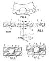
- each pressure plate comprises a metal casting of generally annular outline in which is integrally cast pilot recesses of which only one is illustrated at 2, and from which the final profile of the ball receiving recess and the ramp is generated.
- the pilot recess 2 of the plate 1 shown in Figure 1 is concave in outline.
- a cutting face 4 of part-spherical outline at the outer end of a cutter 3 is inserted into the pilot recess 2 in a direction generally normal to the plane of the plate 1.
- the cutter 3 is then moved inwardly and laterally as shown by arrow 9, whilst traversing a pitch circle 5 on which all the recesses lie, in order to generate a ramp 6.
- the cutter is then withdrawn from the plate 1.
- the curved surface 7 at the deeper end of the final recess defines a stop for a ball 8 in an inoperative position of brake as shown in the assembly of Figure 8 in which two similar pressure plates 1 are superimposed upon each other with balls located in the recesses 2 of complementary pairs to form an actuator unit in the assembled brake.
- the cutter travel indicated is that at lower speed for metal removal.
- a high sided wall is retained along each final recess to ensure effective piloting of the balls 8 of one plate 1 with respect to the other.
- a relief 10 surrounding the pilot recess 2 in each plate 1 is cast integrally with the respective plate.
- the relief minimises the length of the ramp 6 necessary for a ball 8 of a given diameter and lining wear situation.
- pilot recess 2 cast integrally is high sided and of substantial axial depth to facilitate piloting of one pressure plate relative to the other.
- a recess 2 of this profile enables metal to be removed rapidly.
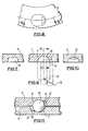
- the integrally cast pilot recess 2 is of frusto-conical outline, the profile of which is shown in chain-dotted line.
- the recess 2 is located at the deeper end of the final recess.
- the cast pilot recess 2 is similar in profile to that of Figure 13 but the edges of the recess 2 are steeper and correspond more closely to the profile of the final recess. As illustrated, this means that only the shaded regions 14 and 15 have to be machined away to produce the final profile.
Landscapes
- Engineering & Computer Science (AREA)
- Mechanical Engineering (AREA)
- General Engineering & Computer Science (AREA)
- Braking Arrangements (AREA)
Applications Claiming Priority (2)
| Application Number | Priority Date | Filing Date | Title |
|---|---|---|---|
| GB858508738A GB8508738D0 (en) | 1985-04-03 | 1985-04-03 | Self-energising disc brakes |
| GB8508738 | 1985-04-03 |
Publications (1)
| Publication Number | Publication Date |
|---|---|
| EP0198623A2 true EP0198623A2 (de) | 1986-10-22 |
Family
ID=10577159
Family Applications (1)
| Application Number | Title | Priority Date | Filing Date |
|---|---|---|---|
| EP19860302320 Withdrawn EP0198623A2 (de) | 1985-04-03 | 1986-03-27 | Selbstverstärkende Scheibenbremsen |
Country Status (3)
| Country | Link |
|---|---|
| EP (1) | EP0198623A2 (de) |
| BR (1) | BR8601481A (de) |
| GB (1) | GB8508738D0 (de) |
-
1985
- 1985-04-03 GB GB858508738A patent/GB8508738D0/en active Pending
-
1986
- 1986-03-27 EP EP19860302320 patent/EP0198623A2/de not_active Withdrawn
- 1986-04-02 BR BR8601481A patent/BR8601481A/pt unknown
Also Published As
| Publication number | Publication date |
|---|---|
| GB8508738D0 (en) | 1985-05-09 |
| BR8601481A (pt) | 1986-12-09 |
Similar Documents
| Publication | Publication Date | Title |
|---|---|---|
| US4653614A (en) | Self-energizing disc brakes | |
| US5480007A (en) | Disc brake rotor | |
| US3792603A (en) | Apparatus for assembling two parts into interlocked and interfitting relationship | |
| EP0463531B1 (de) | Homokinetische Kupplung mit gekreuzten Laufrillen | |
| EP0040027B1 (de) | Scheibenbremsen | |
| EP1588868A1 (de) | Radlagereinheit und verfahren zu deren herstellung | |
| GB2155367A (en) | Forming ball bearing tracks | |
| KR20100097611A (ko) | 차량용 브레이크 디스크 및 그 제조 방법 | |
| EP0198623A2 (de) | Selbstverstärkende Scheibenbremsen | |
| JPS59151635A (ja) | デイスクブレ−キ | |
| DE19611428A1 (de) | Kolbendichtung | |
| US4736820A (en) | Self-energizing disc brakes | |
| US4795003A (en) | Self-energizing disc brakes | |
| EP0209271A2 (de) | Selbstverstärkende Scheibenbremsen | |
| US4067417A (en) | Self-energizing applied wedge actuator | |
| GB2031082A (en) | Spreading disc brakes for vehicles | |
| US3354535A (en) | Composite cylindrical structure and method of making it | |
| RU2768425C2 (ru) | Фрикционный кольцевой элемент, набор фрикционных колец для установки на колесный диск рельсового колеса и тормоз рельсового колеса | |
| US4702351A (en) | Self-energizing disc brakes | |
| DE3800502A1 (de) | Bremsscheibe fuer scheibenbremsen | |
| DE102016210225A1 (de) | Beschichtete Bremsscheibe | |
| EP0189259A2 (de) | Selbsverstärkende Scheibenbremsen | |
| EP0192395A1 (de) | Selbstverstärkende Scheibenbremse | |
| EP0265173A2 (de) | Selbstverstärkende Scheibenbremsen | |
| EP0316070A1 (de) | Selbstverstärkend wirkende Scheibenbremse |
Legal Events
| Date | Code | Title | Description |
|---|---|---|---|
| PUAI | Public reference made under article 153(3) epc to a published international application that has entered the european phase |
Free format text: ORIGINAL CODE: 0009012 |
|
| AK | Designated contracting states |
Kind code of ref document: A2 Designated state(s): DE FR GB IT |
|
| STAA | Information on the status of an ep patent application or granted ep patent |
Free format text: STATUS: THE APPLICATION HAS BEEN WITHDRAWN |
|
| 18W | Application withdrawn |
Withdrawal date: 19870115 |
|
| RIN1 | Information on inventor provided before grant (corrected) |
Inventor name: BASNETT, MICHAEL NEIL Inventor name: PRICE, ANTHONY GEORGE Inventor name: CAMPBELL, ROY |