EP0198136A2 - Optischer Strichkodeprogrammierer für Videorecorder - Google Patents
Optischer Strichkodeprogrammierer für Videorecorder Download PDFInfo
- Publication number
- EP0198136A2 EP0198136A2 EP85305436A EP85305436A EP0198136A2 EP 0198136 A2 EP0198136 A2 EP 0198136A2 EP 85305436 A EP85305436 A EP 85305436A EP 85305436 A EP85305436 A EP 85305436A EP 0198136 A2 EP0198136 A2 EP 0198136A2
- Authority
- EP
- European Patent Office
- Prior art keywords
- data
- memory
- broadcast data
- vcr
- television
- Prior art date
- Legal status (The legal status is an assumption and is not a legal conclusion. Google has not performed a legal analysis and makes no representation as to the accuracy of the status listed.)
- Withdrawn
Links
Images
Classifications
-
- G—PHYSICS
- G06—COMPUTING OR CALCULATING; COUNTING
- G06K—GRAPHICAL DATA READING; PRESENTATION OF DATA; RECORD CARRIERS; HANDLING RECORD CARRIERS
- G06K7/00—Methods or arrangements for sensing record carriers, e.g. for reading patterns
- G06K7/10—Methods or arrangements for sensing record carriers, e.g. for reading patterns by electromagnetic radiation, e.g. optical sensing; by corpuscular radiation
- G06K7/10544—Methods or arrangements for sensing record carriers, e.g. for reading patterns by electromagnetic radiation, e.g. optical sensing; by corpuscular radiation by scanning of the records by radiation in the optical part of the electromagnetic spectrum
- G06K7/10821—Methods or arrangements for sensing record carriers, e.g. for reading patterns by electromagnetic radiation, e.g. optical sensing; by corpuscular radiation by scanning of the records by radiation in the optical part of the electromagnetic spectrum further details of bar or optical code scanning devices
- G06K7/10851—Circuits for pulse shaping, amplifying, eliminating noise signals, checking the function of the sensing device
-
- G—PHYSICS
- G04—HOROLOGY
- G04G—ELECTRONIC TIME-PIECES
- G04G15/00—Time-pieces comprising means to be operated at preselected times or after preselected time intervals
- G04G15/006—Time-pieces comprising means to be operated at preselected times or after preselected time intervals for operating at a number of different times
-
- G—PHYSICS
- G11—INFORMATION STORAGE
- G11B—INFORMATION STORAGE BASED ON RELATIVE MOVEMENT BETWEEN RECORD CARRIER AND TRANSDUCER
- G11B31/00—Arrangements for the associated working of recording or reproducing apparatus with related apparatus
- G11B31/006—Arrangements for the associated working of recording or reproducing apparatus with related apparatus with video camera or receiver
Definitions
- VCR video casette recorders
- the programmable feature of the VCR should ideally be as simple if not more so to operate than the ordinary television controls commonly known and understood.
- Several studies have been made to determine the acceptance of the programming capability by consumers and it has been found that as many as 70% of all VCR owners do not adequately understand the capabilities of their VCR and consequently do not make adequate use of them, including the programming feature. This is particularly troublesome when it is commonly agreed that only the more sophisticated viewers are presently purchasing and using VCR equipment. Consequently, a large and ready market exists for VCR's having programming capability with simple controls to enable the consumer who owns a television to operate the VCR in an equally simplified manner.
- bar code technology is presently available and is in wide use in many industries for various kinds of activities and to contain many kinds of data.
- a common example of bar coded information which is in present everyday use is the supermarket which contains a large number of food items each of which has a bar code indicia printed on the container or label for the goods and which is scanned at the checkout stand to input the coded information into the sophisticated data terminal and produce a price and product listing.
- the concept of bar code technology permits upgrading and changing of various parameters, including price, in the memory of the data terminal or computer without going through the previous requirements of manually marking and remarking prices on products already on the shelves, or simply ignoring changes in prices as they effect existing inventory previously placed on the shelf.
- a VCR owner need only input the bar coded information to the present invention by passing a light pen or the like across the bar code information (as commonly known) and the VCR is automatically instructed and programmed to record the television broadcast corres - ponding to the bar coded information adjacent the program listing in the viewing guide.
- the present invention virtually eliminates the many drawbacks of the programming controls presently available in VCR's.
- the present invention utilizes digital electronic logic elements, and not a microprocessor, without unduly sacrificing capability to achieve the programming function.
- a first input portion of the circuit reads the data of the bar code and converts it from serial to parallel format.
- a second portion of the circuit sequentially loads the parallel data into a memory and provides a feedback signal (such as a "beep") when the programming information has been fully loaded into the memory.
- Another portion of the circuit contains a real time clock and a comparator circuit with the necessary controls to sequentially compare each program with the real time as produced by the clock in a continuous manner until such time as the real time matches a program time, in which event the VCR control is activated and another timing circuit is reset and times down for the length of time programmed into the memory.
- the tuner is automatically switched to the programmed channel, thereby operating the VCR control to automatically record the selected program.
- the VCR control is automatically turned off, and the program data is automatically erased from the memory to make room for additional recording requests.
- the automatic programming input circuit of the present invention is particularly suited for use in the original manufactured VCR, it can be packaged and sold as an add-on unit with such modifications as would be obvious to one of ordinary skill in the art.
- manufacturers of VCR units can incorporate this automatic programming feature in their newer models, and also offer the feature as a retrofit or optional feature to be added to those many thousands of VCR's already sold and in use.
- the other various features presently offered in VCR controls will continue to be used to facilitate and enhance the programming feature. For example, most VCR's provide a means for an operator to view the program data information contained in the program memory by means of a visual display.
- a VCR 20 which has the circuit of the present invention included therein would have a light pen 22 connected thereto with a suitable electrical conductor 24 for reading bar coded information 26 from a typical program guide A, or bar coded information 28, 30 from a newspaper or magazine B, or bar coded information 32 from a direct mail or promotional flier C to program the VCR 20 to record the television broadcast corresponding to the bar coded information as shown on either of A, B, or C.
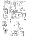
- the circuit of the present invention is shown in block diagram form in Figures 2a and 2b and includes the light pen 22 which is used to "swipe" across a bar code, such as 26 as shown in Figure 1, which produces an electrical signal across the photosensitive diode 34 in series with a resistor 36, the signal from which is input to a comparator circuit 38 to shape the pulses generated by the diode 34, the output of which is input to a bar code reader 40, as known in the art.
- the output of bar code reader 40 is an asynchronous serial data stream, and a control pulse which is input to a shift register 42.
- the programming data is coded to have "N" bits such that a divide by "N” circuit 44 produces a pulse at the end of each byte of data to enable the shift register 42 output and also to pulse the "M” bit counter 46.
- the output of counter 46 is input to a one of "M” decoder 48 which produces an output along one of six output lines to select one of six memory chips 50-60, as shown.
- the divide by "N” circuit 44 produces a pulse to index "M” bit counter 46 which "M” decoder 48 translates to select one of the memory chips 50-60 for storing the data which appears in parallel form and is available along data bus 62.
- each bar code 26 contains six bytes of data. These include the month, day, hour, and minute at which the television broadcast begins that is desired to be programmed. The last two bytes of data include the length of time the program is broadcast, and the channel on which it is being broadcast. With these six bytes of data, the circuit will have complete information to record the desired program.
- a program button 64 is depressed which produces a +1 logic input to inverter 66 which sets the two cross-coupled NOR gates 68, 70, the output of which does several things. For programming purposes, it activates the read input at each of the memory chips 50-60 to ensure that the data is stored therein as the light pen 22 is swiped across the bar code 26. It also indexes counter 72, which contains the location of the highest memory programmed, to increase it by one in response to the entry of another set of program data. The cross-coupled NOR gates 68, 70 also activate gate 74 to permit the address data from counter 72 to program the memory chips 50-60 with the address wherein the data present at shift register 42 is to be stored.
- an inverter 76 inverts the output of cross-coupled NOR gates 68, 70 to inhibit gate 78 and block address data from counter 80 to prevent it from confusing the address data already present on address bus 82 from counter 72.
- Counter 80 is a free-running counter which sequences through the addresses of program data contained in memory chips 50-60, and as a new program is loaded into the circuit, counter 72 creates a new address for that data to be stored in chips 50-60 and also adds the address to counter 80 so that it will be sequenced in turn, as is explained in greater detail below.
- the parity bit check 84 produces an output to AND gate 86 which has its other input connected to the last chip select line of "M" decoder 48 such that its output will go positive at the end of reading the bar code 26.
- a beep circuit 88 is activated to give an audible indication to the operator that the program data has been successfully input to the control.
- AND gate 86 resets "M" bit counter 46 to ready it for the next input of program data, as well as resetting cross-coupled NOR gates 68, 70.
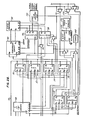
- AND gate 86 also activates buffer 89 to reset counter 90 so that comparator 92 will begin comparing month data from chip 50 with month data from real time clock calendar 94 at the end of a program cycle.
- decoder 98 selects the data from memory chips 50-60, and also selects the proper real time from clock calendar 94 to be fed to comparator 92. This comparison is done sequentially, with month information being first compared. If the data stored in memory corresponding to the month is greater than the actual month, the A B output is activated which resets counter 90, and decrements counter 80 which sequences to the next address corresponding to the next recording programmed into memory chips 50-60. Thus, if all of the recordings requested to be programmed are for one month or more later than the actual month, the comparator circuit 92 will quickly index through each of these programs on a continuous basis without bothering to compare other data.
- comparator circuit 92 compares the month being programmed with the actual month and finds that they are equal, counter 90 is incremented which indexes the address information at outputs Q O -Q 2 to clock calendar 94 to call up the day information and select the day memory chip 52 through decoder 98 so that its output is presented to the other side of comparator circuit 92.
- counter 90 is reset, counter 80 is decremented, and the next program is compared. This continues until the actual time is equal to the month, day, hour, and minute information stored in memory chips 50-56 and counter 90 thus puts a +1 output at its Q 2 output.
- the register 106 has a one minute timer circuit 110 connected to its input which produces a pulse every minute to decrement the counter 106 until it reaches zero. As it reaches zero, it produces an output to stop the VCR control 100 and activate gate 111 to decrement counter 80. The circuit then resumes sequencing through stored program data until another match between real time and stored program request time occurs.
- comparator circuit 92 After a program has been recorded, and the comparator circuit 92 works its way through the comparison process to the same program, it will find that for some of the data stored in memory that it is less than the actual or real time data produced by clock calendar 94. When this occurs, an output is generated by comparator circuit 92 at its A B output to erase the programmed data from memory chips 50-60 and the corresponding memory location from counter 72. For purposes of clarity, the erase circuitry has not been shown as it would be obvious to one of ordinary skill in the art.
Landscapes
- Engineering & Computer Science (AREA)
- Physics & Mathematics (AREA)
- Multimedia (AREA)
- General Physics & Mathematics (AREA)
- Electromagnetism (AREA)
- General Health & Medical Sciences (AREA)
- Health & Medical Sciences (AREA)
- Toxicology (AREA)
- Artificial Intelligence (AREA)
- Computer Vision & Pattern Recognition (AREA)
- Theoretical Computer Science (AREA)
- Management Or Editing Of Information On Record Carriers (AREA)
- Electric Clocks (AREA)
Applications Claiming Priority (2)
| Application Number | Priority Date | Filing Date | Title |
|---|---|---|---|
| US72314785A | 1985-04-15 | 1985-04-15 | |
| US723147 | 1985-04-15 |
Publications (1)
| Publication Number | Publication Date |
|---|---|
| EP0198136A2 true EP0198136A2 (de) | 1986-10-22 |
Family
ID=24905061
Family Applications (1)
| Application Number | Title | Priority Date | Filing Date |
|---|---|---|---|
| EP85305436A Withdrawn EP0198136A2 (de) | 1985-04-15 | 1985-07-30 | Optischer Strichkodeprogrammierer für Videorecorder |
Country Status (2)
| Country | Link |
|---|---|
| EP (1) | EP0198136A2 (de) |
| JP (1) | JPS61237280A (de) |
Cited By (4)
| Publication number | Priority date | Publication date | Assignee | Title |
|---|---|---|---|---|
| FR2610757A1 (fr) * | 1987-02-09 | 1988-08-12 | Pioneer Electronic Corp | Procede et appareil pour controler un appareil de lecture d'un support d'enregistrement de donnees |
| FR2671422A1 (fr) * | 1991-01-04 | 1992-07-10 | Ravard Michel | Dispositif pour mise en marche d'un magnetoscope grace a l'utilisation du code-barre. |
| EP0449985B1 (de) * | 1988-12-23 | 1998-01-21 | Development Corporation Gemstar | Vorrichtung und verfahren zur verwendung von kodierten daten für die zeitvorprogrammierung eines videorecorders/videoabspielers |
| NL1005151C2 (nl) * | 1997-01-31 | 1998-08-03 | Mic O Data B V | Werkwijze en inrichting voor het registreren en/of verwerken van informatie op een informatiedrager. |
-
1985
- 1985-07-30 EP EP85305436A patent/EP0198136A2/de not_active Withdrawn
- 1985-12-27 JP JP29335185A patent/JPS61237280A/ja active Pending
Cited By (7)
| Publication number | Priority date | Publication date | Assignee | Title |
|---|---|---|---|---|
| FR2610757A1 (fr) * | 1987-02-09 | 1988-08-12 | Pioneer Electronic Corp | Procede et appareil pour controler un appareil de lecture d'un support d'enregistrement de donnees |
| NL8702090A (nl) * | 1987-02-09 | 1988-09-01 | Pioneer Electronic Corp | Werkwijze en inrichting voor het besturen van een informatieregistratiemedium-weergeefinrichting. |
| BE1001771A5 (fr) * | 1987-02-09 | 1990-03-06 | Pioneer Electronic Corp | Procede et appareil pour controler un appareil de lecture d'un support d'enregistrement de donnees. |
| EP0449985B1 (de) * | 1988-12-23 | 1998-01-21 | Development Corporation Gemstar | Vorrichtung und verfahren zur verwendung von kodierten daten für die zeitvorprogrammierung eines videorecorders/videoabspielers |
| FR2671422A1 (fr) * | 1991-01-04 | 1992-07-10 | Ravard Michel | Dispositif pour mise en marche d'un magnetoscope grace a l'utilisation du code-barre. |
| NL1005151C2 (nl) * | 1997-01-31 | 1998-08-03 | Mic O Data B V | Werkwijze en inrichting voor het registreren en/of verwerken van informatie op een informatiedrager. |
| WO1998034192A1 (en) * | 1997-01-31 | 1998-08-06 | Mic-O-Data B.V. | Method and device for recording and/or processing information on an information carrier |
Also Published As
| Publication number | Publication date |
|---|---|
| JPS61237280A (ja) | 1986-10-22 |
Similar Documents
| Publication | Publication Date | Title |
|---|---|---|
| US4426684A (en) | Scratch pad memory for cassette of magnetic tape recording | |
| EP0449985B1 (de) | Vorrichtung und verfahren zur verwendung von kodierten daten für die zeitvorprogrammierung eines videorecorders/videoabspielers | |
| US4145715A (en) | Surveillance system | |
| EP0176965B1 (de) | Fernsteuergerät | |
| JP2681027B2 (ja) | Micの読出し機能を有するリモコン送信機及びそのmic内容ディスプレイ方法 | |
| US4499509A (en) | Tape position control apparatus | |
| GB2063541A (en) | Ordering terminal | |
| EP0416706B1 (de) | Anordnung zum Programmieren eines Videorekorders und Videorekorder mit einer derartigen Anordnung | |
| US4536646A (en) | Time accounting system | |
| CA2157895A1 (en) | Interactive system for telephone and video communication including capabilities for remote monitoring | |
| KR910007780B1 (ko) | 비디오 테이프 레코더 | |
| EP0198136A2 (de) | Optischer Strichkodeprogrammierer für Videorecorder | |
| US5396297A (en) | Character display device for displaying characters on a television screen | |
| GB2209090A (en) | Backspace and review facility in video recording and playback | |
| US3924108A (en) | Cash register | |
| EP0368313A3 (de) | Videobandrecorder zum Empfangen einer Teletext Rundfunkübertragung | |
| US5530900A (en) | Display system for selectively displaying different types of information depending upon the detection of non-standard switch selections | |
| JPS6210781A (ja) | バ−コ−ドリ−ダ | |
| US5585857A (en) | Method of transmitting teletext page codes for hexadecimal pages | |
| JPS586671A (ja) | 復号器 | |
| KR950005104B1 (ko) | 브이씨알에서의 바스 어드레스 표제 및 목록 표시장치 및 그 방법 | |
| JPH08235296A (ja) | バーコード読取装置 | |
| KR940011685B1 (ko) | 예약녹화방법 및 장치 | |
| JPS6327129A (ja) | ビデオテ−プレコ−ダの予約装置 | |
| JPH0439829B2 (de) |
Legal Events
| Date | Code | Title | Description |
|---|---|---|---|
| PUAI | Public reference made under article 153(3) epc to a published international application that has entered the european phase |
Free format text: ORIGINAL CODE: 0009012 |
|
| AK | Designated contracting states |
Kind code of ref document: A2 Designated state(s): AT BE CH DE FR GB IT LI LU NL SE |
|
| STAA | Information on the status of an ep patent application or granted ep patent |
Free format text: STATUS: THE APPLICATION HAS BEEN WITHDRAWN |
|
| 18W | Application withdrawn |
Withdrawal date: 19870625 |
|
| RIN1 | Information on inventor provided before grant (corrected) |
Inventor name: O'DONNELL, FRANCIS E. JR. M. D. Inventor name: SHOCKEY, RICHARD D. Inventor name: HILEMAN, H. JAMES |