EP0198087A1 - Detecteur d'artefacts dans la mesure de signaux emis par un corps vivant - Google Patents
Detecteur d'artefacts dans la mesure de signaux emis par un corps vivant Download PDFInfo
- Publication number
- EP0198087A1 EP0198087A1 EP85904868A EP85904868A EP0198087A1 EP 0198087 A1 EP0198087 A1 EP 0198087A1 EP 85904868 A EP85904868 A EP 85904868A EP 85904868 A EP85904868 A EP 85904868A EP 0198087 A1 EP0198087 A1 EP 0198087A1
- Authority
- EP
- European Patent Office
- Prior art keywords
- pulse
- high frequency
- electrocardiogram
- artifact
- comparing
- Prior art date
- Legal status (The legal status is an assumption and is not a legal conclusion. Google has not performed a legal analysis and makes no representation as to the accuracy of the status listed.)
- Granted
Links
- 238000005259 measurement Methods 0.000 title description 2
- 230000002159 abnormal effect Effects 0.000 claims abstract description 14
- 238000001514 detection method Methods 0.000 description 8
- 238000010586 diagram Methods 0.000 description 6
- 206010003119 arrhythmia Diseases 0.000 description 3
- 230000006793 arrhythmia Effects 0.000 description 3
- 238000003745 diagnosis Methods 0.000 description 3
- 230000008030 elimination Effects 0.000 description 3
- 238000003379 elimination reaction Methods 0.000 description 3
- 208000019622 heart disease Diseases 0.000 description 3
- 238000000605 extraction Methods 0.000 description 2
- 230000002265 prevention Effects 0.000 description 2
- 208000009729 Ventricular Premature Complexes Diseases 0.000 description 1
- 230000036982 action potential Effects 0.000 description 1
- 239000000470 constituent Substances 0.000 description 1
- 230000010247 heart contraction Effects 0.000 description 1
- 230000007774 longterm Effects 0.000 description 1
- 230000000007 visual effect Effects 0.000 description 1
Images


Classifications
-
- A—HUMAN NECESSITIES
- A61—MEDICAL OR VETERINARY SCIENCE; HYGIENE
- A61B—DIAGNOSIS; SURGERY; IDENTIFICATION
- A61B5/00—Measuring for diagnostic purposes; Identification of persons
- A61B5/72—Signal processing specially adapted for physiological signals or for diagnostic purposes
- A61B5/7203—Signal processing specially adapted for physiological signals or for diagnostic purposes for noise prevention, reduction or removal
-
- A—HUMAN NECESSITIES
- A61—MEDICAL OR VETERINARY SCIENCE; HYGIENE
- A61B—DIAGNOSIS; SURGERY; IDENTIFICATION
- A61B5/00—Measuring for diagnostic purposes; Identification of persons
- A61B5/24—Detecting, measuring or recording bioelectric or biomagnetic signals of the body or parts thereof
- A61B5/25—Bioelectric electrodes therefor
- A61B5/276—Protection against electrode failure
-
- A—HUMAN NECESSITIES
- A61—MEDICAL OR VETERINARY SCIENCE; HYGIENE
- A61B—DIAGNOSIS; SURGERY; IDENTIFICATION
- A61B5/00—Measuring for diagnostic purposes; Identification of persons
- A61B5/24—Detecting, measuring or recording bioelectric or biomagnetic signals of the body or parts thereof
- A61B5/316—Modalities, i.e. specific diagnostic methods
- A61B5/318—Heart-related electrical modalities, e.g. electrocardiography [ECG]
- A61B5/346—Analysis of electrocardiograms
- A61B5/349—Detecting specific parameters of the electrocardiograph cycle
Definitions
- the present invention relates to an artifact detecting apparatus in the measurement of a biological signal and, in particular, to an apparatus for discriminating the relatively high frequency noise (high frequency artifact) contained in an electrocardiogram signal from the natural electrocardiogram signal and for detecting the presence of the high frequency artifact with a high precision.
- the apparatus according to the present invention is used, for example, in connection with an elimination circuit of the high frequency artifact in an automatic electrocardiogram analyzer, a recognition stopping apparatus for the prevention of misrecognition in an arrhythmia recognition apparatus, and the like.
- an electrocardiogram is used in the diagnosis of cardiac diseases and recorded as a potential difference between the electrodes attached to the limb or chest, corresponding to the change of action potential accompanying a cardiac contraction.
- a typical electrocardiogram waveform is shown in Fig. 1.
- Fig. 2 In the electrocardiogram waveform obtained through actual recording, there often appears a high frequency artifact AF occurring due to myoelectricity, the movement of electrodes and the like as shown in Fig. 2.
- Such a high frequency artifact frequently occurs, particularly in the long term electrocardiogram record which is the electrocardiogram recorded under the condition of living a routine life with a long time electrocardiograph attached to the body.
- a skilled examination engineer visually examines the electrocardiogram waveform, judges whether or not, for example, a portion R (hereinafter referred to as R wave), having high frequency components occurs at an almost constant cycle, and decides the presence or absence of cardiac diseases based on the visual judgement.
- a prior art artifact detecting apparatus is described, for example in Japanese Unexamined Patent Publication (Kokai) No. 55-86444 or US Patent No. 3905364.
- An object of the present invention is to provide an artifact detecting apparatus which enables the presence of the high frequency artifact to be detected with a high precision from an input electrocardiogram signal, and an abnormal electrocardiogram waveform to be discriminated exactly from the high frequency artifact in recognizing the abnormal electrocardiogram waveform.
- an artifact detecting apparatus comprising; a filter for extracting high frequency components from an input electrocardiogram signal; comparing and pulse-generating means for comparing an amplitude voltage of the high frequency components with a preset first predetermined value and for generating a pulse when the amplitude voltage exceeds the first predetermined value; pulse-counting means for counting a pulse within a predetermined time interval from the comparing and pulse-generating means; and comparing and detecting means for comparing a value output from the pulse-counting means with a preset second predetermined value and for detecting an artifact based on the result of the comparison.
- the artifact detecting apparatus detects the high frequency artifact based on the number of appearances of high frequency components (for example, 100 Hz or more) existing in the arbitrary constant time interval of the electrocardiogram signal.
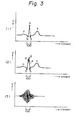
- Figure 3 shows a diagram for explaining the principle of artifact detection according to the apparatus of the present invention.
- the count value of the high frequency components obtained from the electrocardiogram waveform is "3" because the portions at which the electrocardiogram signal has high frequency components are the Q wave, R wave, and S wave, and the time interval between Q wave and S wave is about 60 (msec).
- the count value of the high frequency components obtained from the electrocardiogram waveform is "5" because the portions at which the electrocardiogram signal has high frequency components are the Q wave, R wave, A wave, B wave, and S wave.
- the count value of the high frequency components obtained from the electrocardiogram waveform is "9", because this high frequency artifact has portions having nine high frequency components in the time interval of 100 (msec). Accordingly, it is possible to discriminate the high frequency artifact shown in Fig. 3, (3) from the electrocardiogram waveform by setting the critical number for the judgement for detecting the high frequency artifact to be at least "6".
- the number for the judgement corresponds to the aforementioned first predetermined value and this first predetermined value is preferably set to a voltage value for detecting a portion having high frequency components in either the normal electrocardiogram signal or the abnormal electrocardiogram signal.
- This first predetermined value is a voltage value capable of detecting at least one voltage level of voltage levels corresponding to the points Q, R, and S, respectively, having high frequency components among the section points existing in the electrocardiogram, a voltage value capable of detecting the high frequency artifact having an amplitude voltage value which does not have an influence on the extraction of the section points necessary to the recognition of the abnormal electrocardiogram waveform, and a maximum value of the amplitude voltage under the consideration that if a T wave of the electrocardiogram signal has passed the filter it may have a relatively great amplitude.
- the second predetermined value is preferably set to a value lying between a value output from the pulse-counting means corresponding to the last pulse of the largest pulses among the pulses generated within the predetermined time interval based on the comparison of the first predetermined value with the electrocardiogram signal having passed the filter and a value output from the pulse-counting means corresponding to the pulse preceding the last but one pulse.
- the high frequency artifact can be detected with a high precision by detecting high frequency components of the frequency equal to or more than the predetermined value within a predetermined time interval of the electrocardiogram signal, by counting the components, and by comparing this counted value with a predetermined threshold value.
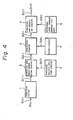
- FIG. 4 One embodiment of the artifact detecting apparatus according to the present invention is shown in Fig. 4, and the signal waveform of each point in the apparatus shown in Fig. 4 is shown in Fig. 5.
- 1 is a high-pass filter.
- This high-pass filter 1 is provided for extracting only high frequency components from an electrocardiogram signal.
- 3 is a comparing and pulse-generating circuit.
- This comparing and pulse-generating circuit 3 is a circuit for converting into pulses an R wave of the normal electrocardiogram, an R wave distorted by the abnormal electrocardiogram due to ventricular extrasystole, and the like, and the high frequency artifact having the amplitude and frequency components approximately to an R wave of the normal electrocardiogram.
- the comparing and pulse-generating circuit 3 is a circuit which compares the output signal S(l) voltage from the high-pass filter 1 with the output signal S(2) (threshold voltage E ) from the threshold voltage setting circuit 2 and generates a pulse or pulses when the output signal S(l) voltage exceeds the threshold voltage E 0 .
- the comparing and pulse-generating circuit 3 may be a Schmitt circuit as a concrete circuit.
- Threshold voltage E 0 set in the threshold voltage setting circuit 2 is set to a voltage value capable of detecting at least one voltage level of voltage levels corresponding to the points Q, R, and S, respectively, having high frequency components among the section points existing in the electrocardiogram, a voltage value capable of detecting the high frequency artifact having an amplitude voltage value which does not have an influence on the extraction of the section points necessary to the recognition of the abnormal electrocardiogram waveform, and a maximum value of the amplitude voltage under the consideration that a T wave of the electrocardiogram signal has passed the filter and may have a relatively great amplitude.
- 5 is an integrating circuit. This integrating circuit 5 is a circuit for integrating the high frequency pulses obtained through the comparing and pulse-generating circuit 3.
- This clock circuit 4 is a clock circuit. This clock circuit 4 generates a pulse S(4) at a predetermined time interval t 0 and resets the integrated output of the integrating circuit 5.
- 6 is a detecting level voltage setting circuit.
- the detecting level voltage E1 is set in this detecting level voltage setting circuit 6.
- This detecting level voltage E 1 is set to a value lying between the integrated output voltage corresponding to the fifth pulse of the pulses input to the integrating circuit 5 and the integrated output voltage corresponding to the sixth pulse, for example, when the predetermined time interval t 0 of the pulse as shown in Fig. 5, (4) is 100 (msec).
- 7 is a comparing and detecting circuit.
- This circuit is a circuit for comparing the output signal S(5) voltage of the integrating circuit 5 with the output signal S(6) (detecting level voltage E1) of the detecting level voltage setting circuit 6 and generating a pulse as an artifact detection signal S(7) at the output terminal OUT when the output signal S(5) voltage exceeds the detecting level voltage E l .
- This artifact detection signal S(7) can be used in the desired application and supplied to, for example, an elimination circuit of the high frequency artifact in an automatic electrocardiogram analyzer or an recognition stopping apparatus for the prevention of misrecognition in an arrhythmia recognition apparatus.
- an elimination circuit of the high frequency artifact the waveform portions at which the high frequency artifact occurs in the electrocardiogram waveform can be automatically eliminated and an electrocardiogram waveform free of the high frequency artifact can be obtained, based on the artifact detection signal from the comparing and detecting circuit 7.
- the mode of operation of the artifact detecting apparatus constituted as above-mentioned will be explained hereinafter.
- the electrocardiogram signal S(c) applied to the input terminal IN as shown in Fig. 5, (1) is input to the high-pass filter 1, where the low frequency components are removed, and the electrocardiogram signal S(l) as shown in Fig. 5, (2) is obtained.
- This electrocardiogram signal S(l) is input to the comparing and pulse-generating circuit 3 and compared with the threshold voltage E 0 from the threshold voltage setting circuit 2, where only the electrocardiogram signal having exceeded the threshold voltage E O is converted into the high frequency pulses S(3) having a single amplitude and a single pulse width as shown in Fig. 5, (3).
- the high frequency pulses obtained in the comparing and pulse-generating circuit 3 are input to the integrating circuit 5 and integrated. Then, the integrating circuit 5 is reset by the output pulse S(4) of the clock circuit 4 as shown in Fig. 5, (4), so that the waveform as shown in Fig. 5, (5) is obtained as the output signal S(5) of the integrating circuit 5.
- the output signal S(5) of the integrating circuit 5 is input to the comparing and detecting circuit 7 and compared with the preset detecting level voltage E 1 . Based on this comparison, the artifact detection signal S(7) as shown in Fig. 5, (6) is obtained at the output terminal OUT as the output of the comparing and detecting circuit 7 when the output signal S(5) voltage of the integrating circuit 5 exceeds the detecting level voltage E l .
- This artifact detection signal S(7) can be used in the desired application as aforementioned.
- the electrocardiogram from the human organism is detected by means of at least the normal twelve leads.
- the normal twelve leads have a different waveform for each lead and include a lead having a positive R wave and a lead having a negative R wave.
- the phenomenon wherein the waveform differs for each lead occurs in the abnormal electrocardiogram waveform as well, and includes a lead having a positive R wave and a lead having a negative R wave. Therefore, the threshold voltage E 0 can be set as negative or as both positive and negative under the consideration of a lead having a negative R wave, although in the above-mentioned embodiment only the case wherein the threshold voltage E 0 input to the comparing and pulse-generating circuit is positive is described. Such a change of the threshold voltage can be readily carried out by changing the value of each constituent element.
- the waveform obtained by converting a negative electrocardiogram waveform in the input signal to positive a so-called absolute value waveform
- absolute value waveform may be generated by means of an inverter when the electrocardiogram signal is input to the comparing and pulse-generating circuit.
- absolute value waveform is generally used in the electrocardiogram analyzer and is well known.
- the integrating circuit is used as the means for counting pulses output from the comparing and pulse-generating circuit.
- the means is not restricted to the integrating circuit and may be a counting circuit such as a binary counter which performs a comparison according to the sequence number.
- the threshold voltage E 0 is set so that the high frequency amplitude voltage of Q, R and S wave can be detected
- the predetermined time interval t 0 is set to contain the high frequency components of the Q, R, and S waves
- the detecting level voltage E 1 is set to a detecting level under the consideration of the high frequency components of arrhythmia.
- the values of the threshold voltage E 0 , the predetermined time interval t 0 , and the detecting level voltage E l are not restricted to the above-mentioned.
- the precision of discrimination of the high frequency artifact can be improved by setting the threshold voltage E 0 so that only the high frequency amplitude voltage of the R wave can be detected, by setting the predetermined time interval t 0 to a shorter interval, and by setting the detecting level voltage E I to a value under the consideration of only the high frequency components of the R wave. Accordingly, the detection of the high frequency artifact can be carried out by appropriately selecting the respective value independently of or dependently on each other according to the purpose of diagnosis.
Landscapes
- Health & Medical Sciences (AREA)
- Life Sciences & Earth Sciences (AREA)
- Cardiology (AREA)
- Engineering & Computer Science (AREA)
- Animal Behavior & Ethology (AREA)
- Biomedical Technology (AREA)
- Public Health (AREA)
- Veterinary Medicine (AREA)
- Medical Informatics (AREA)
- Molecular Biology (AREA)
- Surgery (AREA)
- Biophysics (AREA)
- General Health & Medical Sciences (AREA)
- Pathology (AREA)
- Heart & Thoracic Surgery (AREA)
- Physics & Mathematics (AREA)
- Signal Processing (AREA)
- Artificial Intelligence (AREA)
- Computer Vision & Pattern Recognition (AREA)
- Physiology (AREA)
- Psychiatry (AREA)
- Measurement And Recording Of Electrical Phenomena And Electrical Characteristics Of The Living Body (AREA)
Abstract
Applications Claiming Priority (2)
| Application Number | Priority Date | Filing Date | Title |
|---|---|---|---|
| JP201897/84 | 1984-09-28 | ||
| JP59201897A JPS6179444A (ja) | 1984-09-28 | 1984-09-28 | 生体信号ア−チフアクト検出装置 |
Publications (3)
| Publication Number | Publication Date |
|---|---|
| EP0198087A1 true EP0198087A1 (fr) | 1986-10-22 |
| EP0198087A4 EP0198087A4 (fr) | 1988-05-19 |
| EP0198087B1 EP0198087B1 (fr) | 1992-02-26 |
Family
ID=16448633
Family Applications (1)
| Application Number | Title | Priority Date | Filing Date |
|---|---|---|---|
| EP85904868A Expired EP0198087B1 (fr) | 1984-09-28 | 1985-09-27 | Detecteur d'artefacts dans la mesure de signaux emis par un corps vivant |
Country Status (6)
| Country | Link |
|---|---|
| US (1) | US4796638A (fr) |
| EP (1) | EP0198087B1 (fr) |
| JP (1) | JPS6179444A (fr) |
| AU (1) | AU580107B2 (fr) |
| DE (1) | DE3585441D1 (fr) |
| WO (1) | WO1986001993A1 (fr) |
Cited By (4)
| Publication number | Priority date | Publication date | Assignee | Title |
|---|---|---|---|---|
| FR2626164A1 (fr) * | 1988-01-26 | 1989-07-28 | Gorny Philippe | Procede et dispositif de detection d'anomalies de l'activite cardiaque |
| EP0358303A1 (fr) * | 1988-06-08 | 1990-03-14 | Medtronic, Inc. | Appareil pour détecter et traiter la tachyarhythmie pour un stimulateur, un cardioverteur ou un défibrillateur |
| EP0429025A3 (en) * | 1989-11-17 | 1992-11-19 | Siemens Elema Ab | Noise discrimination in implantable pacemakers |
| GB2335747A (en) * | 1998-03-26 | 1999-09-29 | Hewlett Packard Co | Determination of the quality of heart function signals |
Families Citing this family (36)
| Publication number | Priority date | Publication date | Assignee | Title |
|---|---|---|---|---|
| US4870974A (en) * | 1987-09-30 | 1989-10-03 | Chinese Pla General Hospital | Apparatus and method for detecting heart characteristics by way of electrical stimulation |
| US5842997A (en) * | 1991-02-20 | 1998-12-01 | Georgetown University | Non-invasive, dynamic tracking of cardiac vulnerability by simultaneous analysis of heart rate variability and T-wave alternans |
| US5265617A (en) * | 1991-02-20 | 1993-11-30 | Georgetown University | Methods and means for non-invasive, dynamic tracking of cardiac vulnerability by simultaneous analysis of heart rate variability and T-wave alternans |
| JP3136430B2 (ja) * | 1993-03-15 | 2001-02-19 | 日本光電工業株式会社 | 生体信号測定装置 |
| SE9302435D0 (sv) * | 1993-07-16 | 1993-07-16 | Siemens-Elema Ab | Foerfarande och anordning foer att behandla ekg-signaler |
| EP1158664A3 (fr) * | 1995-03-03 | 2002-02-20 | Agilent Technologies, Inc. (a Delaware corporation) | Procédé d'analyse d'un signal ECG |
| US5650750A (en) * | 1995-03-03 | 1997-07-22 | Heartstream, Inc. | Common mode signal and circuit fault detection in differential signal detectors |
| US5702425A (en) * | 1996-08-13 | 1997-12-30 | Pacesetter, Inc. | Apparatus and method of noise classification in an implantable cardiac device |
| US6287328B1 (en) | 1999-04-08 | 2001-09-11 | Agilent Technologies, Inc. | Multivariable artifact assessment |
| US6169919B1 (en) | 1999-05-06 | 2001-01-02 | Beth Israel Deaconess Medical Center, Inc. | System and method for quantifying alternation in an electrocardiogram signal |
| US6477404B1 (en) | 2000-03-01 | 2002-11-05 | Cardiac Pacemakers, Inc. | System and method for detection of pacing pulses within ECG signals |
| US6687118B1 (en) * | 2000-11-03 | 2004-02-03 | Cardiac Pacemakers, Inc. | Flat capacitor having staked foils and edge-connected connection members |
| US6833987B1 (en) * | 2000-11-03 | 2004-12-21 | Cardiac Pacemakers, Inc. | Flat capacitor having an active case |
| US6509588B1 (en) * | 2000-11-03 | 2003-01-21 | Cardiac Pacemakers, Inc. | Method for interconnecting anodes and cathodes in a flat capacitor |
| US6699265B1 (en) * | 2000-11-03 | 2004-03-02 | Cardiac Pacemakers, Inc. | Flat capacitor for an implantable medical device |
| US6684102B1 (en) * | 2000-11-03 | 2004-01-27 | Cardiac Pacemakers, Inc. | Implantable heart monitors having capacitors with endcap headers |
| US6522525B1 (en) * | 2000-11-03 | 2003-02-18 | Cardiac Pacemakers, Inc. | Implantable heart monitors having flat capacitors with curved profiles |
| US6529000B2 (en) * | 2000-12-29 | 2003-03-04 | Ge Medical Systems Global Technology Company, Llc | Method and system for processing magnetic resonance signals to remove transient spike noise |
| AU2003233437A1 (en) * | 2002-03-26 | 2003-10-13 | National Aeronautics And Space Administration | System for the diagnosis and monitoring of coronary artery disease, acute coronary syndromes, cardiomyopathy and other cardiac conditions |
| US7951479B2 (en) | 2005-05-11 | 2011-05-31 | Cardiac Pacemakers, Inc. | Method and apparatus for porous insulative film for insulating energy source layers |
| US7479349B2 (en) * | 2002-12-31 | 2009-01-20 | Cardiac Pacemakers, Inc. | Batteries including a flat plate design |
| US8691418B2 (en) * | 2003-02-07 | 2014-04-08 | Cardiac Pacemakers, Inc. | Insulative member on battery cathode |
| US7336998B2 (en) * | 2003-06-24 | 2008-02-26 | Cardiac Pacemakers, Inc. | External discrimination between pace pulses at different heart locations |
| US7072709B2 (en) * | 2004-04-15 | 2006-07-04 | Ge Medical Information Technologies, Inc. | Method and apparatus for determining alternans data of an ECG signal |
| US7272435B2 (en) * | 2004-04-15 | 2007-09-18 | Ge Medical Information Technologies, Inc. | System and method for sudden cardiac death prediction |
| US7509159B2 (en) * | 2004-04-15 | 2009-03-24 | Ge Medical Systems Information Technologies, Inc. | Method and apparatus for detecting cardiac repolarization abnormality |
| US20050234353A1 (en) * | 2004-04-15 | 2005-10-20 | Ge Medical Systems Information Technologies, Inc. | Method and apparatus for analysis of non-invasive cardiac parameters |
| US7162294B2 (en) | 2004-04-15 | 2007-01-09 | Ge Medical Systems Information Technologies, Inc. | System and method for correlating sleep apnea and sudden cardiac death |
| US7415304B2 (en) * | 2004-04-15 | 2008-08-19 | Ge Medical Systems Information Technologies, Inc. | System and method for correlating implant and non-implant data |
| US7187966B2 (en) * | 2004-04-15 | 2007-03-06 | Ge Medical Systems Information Technologies, Inc. | Method and apparatus for displaying alternans data |
| US7224575B2 (en) | 2004-07-16 | 2007-05-29 | Cardiac Pacemakers, Inc. | Method and apparatus for high voltage aluminum capacitor design |
| KR20060053812A (ko) * | 2004-11-17 | 2006-05-22 | 삼성전자주식회사 | 생체신호를 이용한 생체 인식 장치 및 방법 |
| KR100718125B1 (ko) * | 2005-03-25 | 2007-05-15 | 삼성전자주식회사 | 생체신호와 인공신경회로망을 이용한 생체인식 장치 및방법 |
| US8761875B2 (en) | 2006-08-03 | 2014-06-24 | Cardiac Pacemakers, Inc. | Method and apparatus for selectable energy storage partitioned capacitor |
| TW201023828A (en) * | 2008-12-26 | 2010-07-01 | Ind Tech Res Inst | Detecting heartbeat method |
| CN103720468B (zh) * | 2013-12-05 | 2015-07-29 | 深圳先进技术研究院 | 应用于动态心电数据的伪差识别方法和装置 |
Citations (2)
| Publication number | Priority date | Publication date | Assignee | Title |
|---|---|---|---|---|
| US3602222A (en) * | 1968-09-16 | 1971-08-31 | Honeywell Inc | Rate meter, particularly a beat-by-beat cardiotachometer |
| US4237903A (en) * | 1979-01-31 | 1980-12-09 | Hellige Gmbh | QRS detector for EKG signals |
Family Cites Families (8)
| Publication number | Priority date | Publication date | Assignee | Title |
|---|---|---|---|---|
| US3903874A (en) * | 1973-08-27 | 1975-09-09 | Mediscience Technology Corp | Cardiographic signal processing means and method |
| US3905364A (en) * | 1974-04-17 | 1975-09-16 | Marquette Electronics Inc | Artifact detector |
| JPS5190783A (fr) * | 1975-02-04 | 1976-08-09 | ||
| AU518573B2 (en) * | 1978-01-18 | 1981-10-08 | American Optical Corporation | Pacemaker artifact supression in coronary monitoring |
| US4331157A (en) * | 1980-07-09 | 1982-05-25 | Stimtech, Inc. | Mutually noninterfering transcutaneous nerve stimulation and patient monitoring |
| AU549716B2 (en) * | 1980-11-18 | 1986-02-06 | University Patents Inc. | Electrocardiographic means for detecting potential ventricular trachycardia |
| US4478224A (en) * | 1982-11-26 | 1984-10-23 | Camino Laboratories, Inc. | Artifact detector for heartbeat rate measuring system |
| JP2953482B2 (ja) * | 1992-01-17 | 1999-09-27 | 日本電気株式会社 | Cmos集積回路 |
-
1984
- 1984-09-28 JP JP59201897A patent/JPS6179444A/ja active Granted
-
1985
- 1985-09-27 DE DE8585904868T patent/DE3585441D1/de not_active Expired - Fee Related
- 1985-09-27 EP EP85904868A patent/EP0198087B1/fr not_active Expired
- 1985-09-27 AU AU49572/85A patent/AU580107B2/en not_active Ceased
- 1985-09-27 WO PCT/JP1985/000538 patent/WO1986001993A1/fr active IP Right Grant
-
1988
- 1988-03-10 US US07/169,144 patent/US4796638A/en not_active Expired - Fee Related
Patent Citations (2)
| Publication number | Priority date | Publication date | Assignee | Title |
|---|---|---|---|---|
| US3602222A (en) * | 1968-09-16 | 1971-08-31 | Honeywell Inc | Rate meter, particularly a beat-by-beat cardiotachometer |
| US4237903A (en) * | 1979-01-31 | 1980-12-09 | Hellige Gmbh | QRS detector for EKG signals |
Non-Patent Citations (1)
| Title |
|---|
| See also references of WO8601993A1 * |
Cited By (6)
| Publication number | Priority date | Publication date | Assignee | Title |
|---|---|---|---|---|
| FR2626164A1 (fr) * | 1988-01-26 | 1989-07-28 | Gorny Philippe | Procede et dispositif de detection d'anomalies de l'activite cardiaque |
| EP0327427A1 (fr) * | 1988-01-26 | 1989-08-09 | Philippe Gorny | Procédé et dispositif de détection d'anomalies de l'activité cardiaque |
| EP0358303A1 (fr) * | 1988-06-08 | 1990-03-14 | Medtronic, Inc. | Appareil pour détecter et traiter la tachyarhythmie pour un stimulateur, un cardioverteur ou un défibrillateur |
| EP0429025A3 (en) * | 1989-11-17 | 1992-11-19 | Siemens Elema Ab | Noise discrimination in implantable pacemakers |
| GB2335747A (en) * | 1998-03-26 | 1999-09-29 | Hewlett Packard Co | Determination of the quality of heart function signals |
| GB2335747B (en) * | 1998-03-26 | 2002-05-22 | Hewlett Packard Co | Signalling heart function |
Also Published As
| Publication number | Publication date |
|---|---|
| AU580107B2 (en) | 1989-01-05 |
| WO1986001993A1 (fr) | 1986-04-10 |
| JPS6179444A (ja) | 1986-04-23 |
| EP0198087A4 (fr) | 1988-05-19 |
| EP0198087B1 (fr) | 1992-02-26 |
| US4796638A (en) | 1989-01-10 |
| AU4957285A (en) | 1986-04-17 |
| DE3585441D1 (de) | 1992-04-02 |
| JPH0526489B2 (fr) | 1993-04-16 |
Similar Documents
| Publication | Publication Date | Title |
|---|---|---|
| US4796638A (en) | Artifact detecting apparatus in the measurement of a biological signal | |
| US4757824A (en) | Method and apparatus for monitoring respiration | |
| US6477404B1 (en) | System and method for detection of pacing pulses within ECG signals | |
| US5702425A (en) | Apparatus and method of noise classification in an implantable cardiac device | |
| EP0917887B1 (fr) | Un système de détection d'evènements cardiaques pour un stimulateur cardiaque | |
| EP0280529B1 (fr) | Appareil d'électrocardiographie | |
| US5660184A (en) | Pacemaker pulse detection and artifact rejection | |
| US20080051844A1 (en) | Detection of function of implanted medical devices | |
| EP0850593B1 (fr) | Appareil pour le comptage précis de battements cardiaques stimulés | |
| US5305761A (en) | Ambulatory monitor | |
| CA1258099A (fr) | Electoencephalogramme a reconnaissance de l'onde delta au moyen d'un signal de seconde differentiation | |
| EP0321764A1 (fr) | Méthode et moyens pour détecter un évènement dans un signal | |
| US6304772B1 (en) | Method and apparatus for automatically detecting and interpreting paced electrocardiograms | |
| US4453551A (en) | Apparatus for pattern recognition of ECG signals for detecting fibrillation | |
| EP0203004B1 (fr) | Appareil de mesure de la pression sanguine | |
| EP0249824B1 (fr) | Stimulateur cardiaque pour entraîner le coeur humain | |
| CN116849669A (zh) | 一种心电信号信号处理系统及除颤器 | |
| GB2123560A (en) | Cardiac event recognition techniques for use with a delta modulator | |
| EP0878210B1 (fr) | Détection de la réponse du coeur chez les patients muni d'un stimulateur cardiaque | |
| GB2070871A (en) | Pattern recognition | |
| RU2312593C1 (ru) | Способ выделения начала кардиоцикла в реальном времени и устройство для его осуществления | |
| SU1641272A1 (ru) | Устройство дл выделени желудочковых экстрасистол | |
| JPH06154342A (ja) | ペースメーカパルス検出回路 | |
| JPS6122564Y2 (fr) | ||
| Kejariwal | A QRS detection algorithm for discriminating artifacts in ECG records |
Legal Events
| Date | Code | Title | Description |
|---|---|---|---|
| PUAI | Public reference made under article 153(3) epc to a published international application that has entered the european phase |
Free format text: ORIGINAL CODE: 0009012 |
|
| AK | Designated contracting states |
Kind code of ref document: A1 Designated state(s): DE FR GB IT NL |
|
| 17P | Request for examination filed |
Effective date: 19861003 |
|
| A4 | Supplementary search report drawn up and despatched |
Effective date: 19880519 |
|
| RAP1 | Party data changed (applicant data changed or rights of an application transferred) |
Owner name: KABUSHIKI KAISYA ADVANCE |
|
| 17Q | First examination report despatched |
Effective date: 19901010 |
|
| GRAA | (expected) grant |
Free format text: ORIGINAL CODE: 0009210 |
|
| AK | Designated contracting states |
Kind code of ref document: B1 Designated state(s): DE FR GB IT NL |
|
| ITF | It: translation for a ep patent filed | ||
| REF | Corresponds to: |
Ref document number: 3585441 Country of ref document: DE Date of ref document: 19920402 |
|
| ET | Fr: translation filed | ||
| ITTA | It: last paid annual fee | ||
| PLBE | No opposition filed within time limit |
Free format text: ORIGINAL CODE: 0009261 |
|
| STAA | Information on the status of an ep patent application or granted ep patent |
Free format text: STATUS: NO OPPOSITION FILED WITHIN TIME LIMIT |
|
| 26N | No opposition filed | ||
| PGFP | Annual fee paid to national office [announced via postgrant information from national office to epo] |
Ref country code: DE Payment date: 19930831 Year of fee payment: 9 |
|
| PGFP | Annual fee paid to national office [announced via postgrant information from national office to epo] |
Ref country code: GB Payment date: 19930917 Year of fee payment: 9 |
|
| PGFP | Annual fee paid to national office [announced via postgrant information from national office to epo] |
Ref country code: NL Payment date: 19930930 Year of fee payment: 9 Ref country code: FR Payment date: 19930930 Year of fee payment: 9 |
|
| PG25 | Lapsed in a contracting state [announced via postgrant information from national office to epo] |
Ref country code: GB Effective date: 19940927 |
|
| PG25 | Lapsed in a contracting state [announced via postgrant information from national office to epo] |
Ref country code: NL Effective date: 19950401 |
|
| NLV4 | Nl: lapsed or anulled due to non-payment of the annual fee | ||
| GBPC | Gb: european patent ceased through non-payment of renewal fee |
Effective date: 19940927 |
|
| PG25 | Lapsed in a contracting state [announced via postgrant information from national office to epo] |
Ref country code: FR Effective date: 19950531 |
|
| PG25 | Lapsed in a contracting state [announced via postgrant information from national office to epo] |
Ref country code: DE Effective date: 19950601 |
|
| REG | Reference to a national code |
Ref country code: FR Ref legal event code: ST |