EP0197994B1 - Shielded electrical connector - Google Patents
Shielded electrical connector Download PDFInfo
- Publication number
- EP0197994B1 EP0197994B1 EP85905030A EP85905030A EP0197994B1 EP 0197994 B1 EP0197994 B1 EP 0197994B1 EP 85905030 A EP85905030 A EP 85905030A EP 85905030 A EP85905030 A EP 85905030A EP 0197994 B1 EP0197994 B1 EP 0197994B1
- Authority
- EP
- European Patent Office
- Prior art keywords
- cable
- housing
- shield
- connector
- connector assembly
- Prior art date
- Legal status (The legal status is an assumption and is not a legal conclusion. Google has not performed a legal analysis and makes no representation as to the accuracy of the status listed.)
- Expired
Links
Images


Classifications
-
- H—ELECTRICITY
- H01—ELECTRIC ELEMENTS
- H01R—ELECTRICALLY-CONDUCTIVE CONNECTIONS; STRUCTURAL ASSOCIATIONS OF A PLURALITY OF MUTUALLY-INSULATED ELECTRICAL CONNECTING ELEMENTS; COUPLING DEVICES; CURRENT COLLECTORS
- H01R13/00—Details of coupling devices of the kinds covered by groups H01R12/70 or H01R24/00 - H01R33/00
- H01R13/648—Protective earth or shield arrangements on coupling devices, e.g. anti-static shielding
- H01R13/658—High frequency shielding arrangements, e.g. against EMI [Electro-Magnetic Interference] or EMP [Electro-Magnetic Pulse]
- H01R13/6581—Shield structure
- H01R13/6582—Shield structure with resilient means for engaging mating connector
-
- H—ELECTRICITY
- H01—ELECTRIC ELEMENTS
- H01R—ELECTRICALLY-CONDUCTIVE CONNECTIONS; STRUCTURAL ASSOCIATIONS OF A PLURALITY OF MUTUALLY-INSULATED ELECTRICAL CONNECTING ELEMENTS; COUPLING DEVICES; CURRENT COLLECTORS
- H01R13/00—Details of coupling devices of the kinds covered by groups H01R12/70 or H01R24/00 - H01R33/00
- H01R13/58—Means for relieving strain on wire connection, e.g. cord grip, for avoiding loosening of connections between wires and terminals within a coupling device terminating a cable
-
- H—ELECTRICITY
- H01—ELECTRIC ELEMENTS
- H01R—ELECTRICALLY-CONDUCTIVE CONNECTIONS; STRUCTURAL ASSOCIATIONS OF A PLURALITY OF MUTUALLY-INSULATED ELECTRICAL CONNECTING ELEMENTS; COUPLING DEVICES; CURRENT COLLECTORS
- H01R13/00—Details of coupling devices of the kinds covered by groups H01R12/70 or H01R24/00 - H01R33/00
- H01R13/648—Protective earth or shield arrangements on coupling devices, e.g. anti-static shielding
- H01R13/658—High frequency shielding arrangements, e.g. against EMI [Electro-Magnetic Interference] or EMP [Electro-Magnetic Pulse]
- H01R13/6591—Specific features or arrangements of connection of shield to conductive members
- H01R13/65912—Specific features or arrangements of connection of shield to conductive members for shielded multiconductor cable
-
- H—ELECTRICITY
- H01—ELECTRIC ELEMENTS
- H01R—ELECTRICALLY-CONDUCTIVE CONNECTIONS; STRUCTURAL ASSOCIATIONS OF A PLURALITY OF MUTUALLY-INSULATED ELECTRICAL CONNECTING ELEMENTS; COUPLING DEVICES; CURRENT COLLECTORS
- H01R13/00—Details of coupling devices of the kinds covered by groups H01R12/70 or H01R24/00 - H01R33/00
- H01R13/648—Protective earth or shield arrangements on coupling devices, e.g. anti-static shielding
- H01R13/658—High frequency shielding arrangements, e.g. against EMI [Electro-Magnetic Interference] or EMP [Electro-Magnetic Pulse]
- H01R13/6591—Specific features or arrangements of connection of shield to conductive members
- H01R13/6592—Specific features or arrangements of connection of shield to conductive members the conductive member being a shielded cable
- H01R13/6593—Specific features or arrangements of connection of shield to conductive members the conductive member being a shielded cable the shield being composed of different pieces
Definitions
- the invention relates to a shielded electrical connector.
- US-A-4 449 778 a shielded electrical connector assembly of the type having a forward mating portion and a rear cable connecting portion, the assembly comprising a terminal housing, upper and lower ground shields, and upper and lower insulative cover parts.
- the lower ground shield has a base panel with a pair of sidewalls and a rearward upstanding therefrom and a forward contact portion extending away from said rearwall.
- the lower cover part has a base panel with a pair of sidewalls and a rearwall upstanding therefrom, the panel, sidewalls, and rearwall of said lower shield fitting against the panel, sidewalls, and rearwall of said lower cover when said connector is assembled.
- the forward contact portion fits against the housing, the housing having a terminal support platform flanked by a pair of upstanding sidewalls bridged by a hood toward the forward end thereof, the upper shield having forward contact portions which fit against the hood facing the platform, the forward contact portions of the upper shield engaging the forward contact portions of the lower shield when the connector is mated with a like connector.
- the lower ground shield and lower cover part of the known connector each have a panel with a wall upstanding therefrom, the walls each having a cable receiving opening therein which opens away from the respective panels, the openings being aligned for reception of a cable when the lower ground shield is assembled inside the lower cover part.
- the known connector does not have continuous shielding along the sides thereof when mated with another connector. Grounding currents in the cable shield connected to one connector pass only through forward contact portions of the upper and lower shields. It has been discovered that mere proximity of shields in complementary mated connectors does not provide effective interference shielding, especially when high signal frequencies (on the order of 400 MHz) are involved.
- a shielded electrical connector as described above is characterized in that the lower shield has a pair of wings extending forward from respective sidewalls thereof, the wings being assembled between respective sidewalls of the housing to lie between the terminal support platform and the hood.
- Each wing has a flange lying against the respective housing sidewall and a resilient tongue which extends beyond said sidewall for engaging the flange on the wing in a complementary connector.
- the shielding is thus electrically continuous around the junction when the connectors are mated, leaving no "holes" which could cause interference.
- the inventive connector is also designed for economy of manufacture; coring of molded parts is accomplished in two orthogonal directions so that multicavity molds are possible.
- the connector also offers ease of assembly.
- the lower shield is emplaced by moving into the rear of the housing and the lower cover part is then likewise emplaced by movement toward the rear until it latchably engages the housing to hold the lower shield in place.
- the cable receiving opening in the upstanding wall of the lower shield is flanked by a pair of integrally formed flanges which fit substantially flushly into the cable receiving opening in the upstanding wall of the lower cover part.
- the lower cover part has a pair of parallel flanges flanking the opening therein on the outside surface of the upstanding wall thereof, the flanges being collectively profiled as a dovetail.
- the assembly further comprises an inserter member having an aperture therethrough, the aperture opening in the dovetail slot on a mating face of the inserter member, the dovetail slot being profiled to engage the dovetail flanges on the outer wall of the lower cover part by movement of the inserter member perpendicularly toward the plane of the panel of the lower cover part.
- the assembly further comprises a metal contact ferrule profiled to fit between the individual conductors and the shield of a cable.
- a metal contact ferrule profiled to fit between the individual conductors and the shield of a cable Upon assembling the lower ground shield ' to the lower cover part, assembling the cable through the inserter member, stripping the outer insulation from the end protruding from the mating face to expose the cable, and inserting the ferrule between the individual conductors and the exposed cable shield, the exposed cable shield can be forced between the flanges of the lower shield when the dovetail slot in the inserter is mated with the dovetail flanges on the lower cover part.
- the inventive connector provides the advantage of assured contact integrity between the lower shield and the cable shield, which upon mating with a complementary connector assures continuity of ground between shields of respective cables.
- FIG. 1 shows a terminal housing 10 with which the assembly sequence begins.
- the housing 10 has a terminal support platform 13 extending from a front end 11 to a rear end 12 where terminals 2 are received.
- Each terminal 2 has a wire barrel 4, a mating tongue 6, and a base portion 7 extending therebetween; the base portion 7 is received in the respective channel 17 in the platform 13.
- the platform is flanked by sidewalls 18 upstanding therefrom, which sidewalls have rearward facing shoulders 19 on respective inside faces thereof and shielding channels 21 extending forward from the shoulders 19.
- Partitions 24 flank the inside faces of the sidewalls 18 forward of shoulders 19 and define slots 25 below channels 21.
- a hood 28 bridges the sidewalls 18 at this end.
- Shunt assembly 30 is shown poised for reception between shoulders 19 and a post 23 upstanding from the platform 13 between the two central channels 17.
- Lower shield 40 comprises a base panel 41 from which integrally formed forward contact portion 42 extends and sidewalls 43 upstand.
- Rearwall portions 44 are formed from respective sidewalls 43 to flank base panel 41 and define a cable receiving opening 55 therebetween.
- Each rearwall portion 44 is formed with a flange 45 flanking opening 55, each flange 45 being formed with detents 46.
- a resilient tongue 47 extends from the panel 41 into opening 55.
- Forward wings 48 are formed from respective sidewalls 43 at respective first bends 49 which define rearward facing shoulders on opposed surfaces thereof.
- the wings 48 are also formed with second bends 50 defining forward facing shoulders on opposed surfaces thereof.
- a mating flange 51 and a resilient tongue 53 extend forwardly from each shoulder 50; the flange 51 has an outwardly curled lip 52 for mating with the tongue of a like connector.
- Figure 2 shows the lower shield 40 assembled to housing 10; forward wings 48 are flush against inside surfaces of sidewalls 18 in the housing and forward facing shoulders 50 on the shield abut rearward facing shoulders 19 on the housing. Tongues 53 lie in slots 25 with the flange 51 offset thereabove..
- the channel 21 ( Figure 1) allows passage of lip 52 therethrough during assembly.
- the shunt assembly 30 is latchably emplaced after the shield 40 is assembled to housing 10.
- the lower cover 60 comprises a base panel 61 having integrally molded sidewalls 63 and rearwalls 68 upstanding therefrom.
- a latch 62 upstanding from the center of base 61 serves to retain the cover 60 with housing 10 (Figure 7B).
- Sidewalls 63 have respective horizontal mating ribs 64 extending forwardly therefrom for mating with housing 10 ( Figure 7C) and vertical mating ribs 65 for reception between rear face 12 of housing 10 and shoulder 49 of lower shield 40.
- the rearwalls 68 define a cable opening 69 therebetween and have respective flanges 71 extending from outside surfaces 70 and flanking opening 69.
- the flanges 72 taken together are profiled as a dovetail intersected by opening 69.
- Notches 74 are formed at the interstice of each sidewall/ rearwall pair, the notches 74 each having a shoulder 75 therein for retention of the upper cover 110 ( Figure 3).
- the latch arm 78 is molded with a T-member 79 for mating with a complementary connector.
- Figure 3 depicts the lower cover 60 assembled to the lower shield 40 and housing 10.
- the flanges 45 fit flushly against flanges 71 on rearwalls 68.
- the inserter assembly shown in greater detail in Figures 6A and 6B, comprises cable 80, inserter member 87, and stuffer 97.
- the inserter member 87 comprises a rearward gripping portion 88 and a mating flange 89 which is profiled with a dovetail slot 90 for receiving the dovetail ridges 72 on the lower cover 60.
- a contact ferrule 94 is fit between individual insulated conductors 81 and braided shield 82 to insure good grounding contact between flanges 45 and the braid 82; detents 46 serve to retain ferrule 94.
- An upper shield 100 comprise a base panel 101, forward contact tongues 102, and resilient side members 103 which are received against inside faces of respective sidewalls 43 on lower shield 40.
- Resilient tongue 104 like tongue 47 below, serves to contact braid 82.
- Upper cover 110 comprises a panel portion 112, lock arms 114, and a latch arm 117 having a T-slot 118 for retention with a complementary connector. Aligning posts 116 are received in channels 66; the rounded surfaces of posts 116 serve to cam the cover 110 forward to fit snugly against hood 28.
- the upper shield 100 is assembled to upper cover 110 by staking plastic studs in through holes 105 and assembled to lower cover 60 and housing 10 after inserter 87 and stuffer 97 are applied thereto by latching arms 114 with shoulders 75 in notches 74.
- Figure 4 shows the exploded components of shunt assembly 30, which comprises a dielectric carrier 31, shunt members 36, 38 for bridging alternative terminals, and a dielectric spacer 35 therebetween.
- the carrier 31 has staking pegs 32 for fixing members 36, 38 thereto and channels 33 which permit flexure of the shunt contacts 37, 39.
- Latches 34 cooperate with apertures 20 in sidewalls 18 of housing 10 to retain the assembly 30 (Figure 1) which is positioned between shoulders 19 and post 23.
- the assembled connector is shown in Figure 5; like the connector disclosed in US-A-4 449 778, it is an hermaphroditic connector designed to mate with a like connector inverted so that T-bars 79 mate with T-slots 118. Further, the connector of the present invention is designed to mate with a connector of the type disclosed in US-A-4 449 778; the resilient tongues 53, which mate with respective flanges 51 in a like connector, do not preclude mating with the prior art connector.
- Figure 6A shows the inserter member having cable 80 fed through axial aperture 92 therein and emerging from mating flange 89.
- the insulation 83 is stripped to expose braid 82 and a strain relief ferrule 84 is crimped to the insulation 83 adjacent the exposed braid.
- Flange 85 on ferrule 84 is profiled to nest in countersink 93 in mating flange 89, as shown in Figure 6B, thus preventing strain on the conductor terminations when axial force is applied on cable 80.
- the contact ferrule 95 is shown loosely fit on exposed conductors 81. This is subsequently fit concentrically within braid 82, the clamp 96 is applied, and the braid trimmed as shown in Figure 6B.
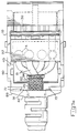
- Figure 7A is a plan view of the assembled connector with the upper cover removed.
- the stuffer 97 has been used to force the individual insulated conductors 81 into the wire barrels 4 of the terminal 2 in conventional fashion.
- the dovetail slot 91 on mating flange 89 of inserter member 87 is engaged with dovetail flanges 72, offering a major advantage of the inventive connector, to wit, compressive force is maintained on the contact ferrule 94 within braid 82. This assures that the electrical contact between the braid 82 and lower ground shield 40 will be maintained, while contact forces tend to relax in known prior art arrangements.
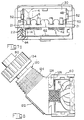
- Figure 7B is a partial side sectibn view of the assembled connector. This view details the cooperation between housing 10, lower shield 40, and lower cover part 60.
- the housing 10 has a terminal support platform 13 with a forward extension 15 and an opposed bottom recess 14.
- a shield slot 16 extends through the housing 10 and receives forward contact portions 42 of lower shield 40 therethrough to lie below extension 15. The contact portions 42 so emplaced provide mating surfaces for contact tongues 102 of an upper shield 100 in a complementary connector.
- the lower cover part 60 protects the base panel 41 of lower shield 40 and is held in place by cooperation of latch 62 in recess 14.
- Figure 7C is an end view showing the cooperation between ribs 64 on lower cover 60 and channels 22 in housing 10 which serves to support the two parts in mated condition.
- the forward wings 48 of lower shield 40 are shown emplaced against sidewalls 18 with the tongues 53 in respective slots 25 and extending therebeyond (Figure 2) for mating against the flange 51 of a like shield in a complementary connector.
- the lip 52 is formed outward to permit mating without interference.
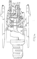
- Figure 8 depicts an alternative inserter 120 which provides for terminating the cable 80 at 45 degrees to the lower cover part 60.
- the inserter 120 comprises a threaded portion 124 which receives an internally threaded compression cap d134 and a mating portion 125 having a dovetail slot 126 which mates with flanges 72 as previously described.
- This inserter 120 can be inverted to permit termination of cable 80 at a second orientation 45 degrees to the lower cover part. Cable clamping to provide strain relief for termination of conductors 81 is provided by applying compression nut to threaded portion 124.
- the alternative inserter 120 is conveniently molded in two halves 121 connected by a hinge 122.
- Each half 121 has a cable receiving bore portion 128 which in cooperation with the other bore portion forms a passage through the assembled inserter 120.
- Each bore portion is profiled with flanges 130, 131, ridges 132, and a spike 133 for progressively bearing on the outer jacket of cable 80 as nut 134 ( Figure 8) is threaded into position.
- This arrangement eliminates the need for a strain relief ferrule 84 as previously described.
Landscapes
- Details Of Connecting Devices For Male And Female Coupling (AREA)
Applications Claiming Priority (4)
| Application Number | Priority Date | Filing Date | Title |
|---|---|---|---|
| US66651784A | 1984-10-30 | 1984-10-30 | |
| US66657384A | 1984-10-30 | 1984-10-30 | |
| US666517 | 1984-10-30 | ||
| US666573 | 1984-10-30 |
Publications (2)
| Publication Number | Publication Date |
|---|---|
| EP0197994A1 EP0197994A1 (en) | 1986-10-22 |
| EP0197994B1 true EP0197994B1 (en) | 1988-11-23 |
Family
ID=27099474
Family Applications (1)
| Application Number | Title | Priority Date | Filing Date |
|---|---|---|---|
| EP85905030A Expired EP0197994B1 (en) | 1984-10-30 | 1985-09-30 | Shielded electrical connector |
Country Status (7)
| Country | Link |
|---|---|
| EP (1) | EP0197994B1 (ko) |
| KR (1) | KR910006167B1 (ko) |
| DE (1) | DE3566479D1 (ko) |
| HK (1) | HK106991A (ko) |
| IE (1) | IE56913B1 (ko) |
| SG (1) | SG95791G (ko) |
| WO (1) | WO1986002781A1 (ko) |
Families Citing this family (4)
| Publication number | Priority date | Publication date | Assignee | Title |
|---|---|---|---|---|
| US5538434A (en) * | 1994-05-18 | 1996-07-23 | The Whitaker Corporation | Electrical connector with integral shorting assembly |
| DE29514610U1 (de) * | 1995-09-12 | 1995-11-09 | Hts Elektrotech Gmbh & Co Kg | Multiaxialsteckverbinder |
| JP2006066242A (ja) * | 2004-08-27 | 2006-03-09 | Tyco Electronics Amp Kk | フラットケーブル用電気コネクタおよびこれに用いられるシールド部材 |
| GB2465609B (en) * | 2008-11-25 | 2012-08-15 | C & C Marshall Ltd | Connector |
Family Cites Families (2)
| Publication number | Priority date | Publication date | Assignee | Title |
|---|---|---|---|---|
| FR2450524A1 (fr) * | 1979-02-28 | 1980-09-26 | Superflexit Sa | Boitier de derivation etanche pour canalisations electriques ou de fluides |
| US4449778A (en) * | 1982-12-22 | 1984-05-22 | Amp Incorporated | Shielded electrical connector |
-
1985
- 1985-09-30 KR KR1019860700404A patent/KR910006167B1/ko not_active IP Right Cessation
- 1985-09-30 EP EP85905030A patent/EP0197994B1/en not_active Expired
- 1985-09-30 WO PCT/US1985/001867 patent/WO1986002781A1/en active IP Right Grant
- 1985-09-30 DE DE8585905030T patent/DE3566479D1/de not_active Expired
- 1985-10-25 IE IE2653/85A patent/IE56913B1/en not_active IP Right Cessation
-
1991
- 1991-11-12 SG SG957/91A patent/SG95791G/en unknown
- 1991-12-23 HK HK1069/91A patent/HK106991A/xx not_active IP Right Cessation
Also Published As
| Publication number | Publication date |
|---|---|
| EP0197994A1 (en) | 1986-10-22 |
| DE3566479D1 (en) | 1988-12-29 |
| IE56913B1 (en) | 1992-01-29 |
| WO1986002781A1 (en) | 1986-05-09 |
| KR910006167B1 (ko) | 1991-08-16 |
| KR880700499A (ko) | 1988-03-15 |
| HK106991A (en) | 1992-01-03 |
| SG95791G (en) | 1991-12-13 |
| IE852653L (en) | 1986-04-30 |
Similar Documents
| Publication | Publication Date | Title |
|---|---|---|
| US4671599A (en) | Shielded electrical connector | |
| US4641906A (en) | Shielded electrical connector | |
| US4653825A (en) | Shielded electrical connector assembly | |
| US4508415A (en) | Shielded electrical connector for flat cable | |
| US5387130A (en) | Shielded electrical cable assembly with shielding back shell | |
| US4884981A (en) | Shielded data connector | |
| KR100212589B1 (ko) | 차폐식 전기 컨넥터 | |
| US5380216A (en) | Cable backpanel interconnection | |
| US5195909A (en) | Insulative backshell system providing strain relief and shield continuity | |
| US5934942A (en) | Shielded electrical connector assembly | |
| US5460545A (en) | Patch connector | |
| US5586911A (en) | Shielding data connector | |
| US5205761A (en) | Shielded connector assembly for coaxial cables | |
| US5632634A (en) | High frequency cable connector | |
| CA1068023A (en) | Female connector and escutcheon plate combined therewith for telephone equipment | |
| US4491381A (en) | Electrical panelboard connector | |
| EP0390450A1 (en) | Back-to-back stackable connector for interface bus | |
| US4701139A (en) | Shielded cable assembly | |
| JPH06203893A (ja) | コネクタ | |
| JPH04215275A (ja) | Lan用リセプタクル組立体 | |
| US5083934A (en) | Electrical connector system | |
| EP0294460B1 (en) | Shielded data connector | |
| AU668594B2 (en) | Electrical connector assembly | |
| US4299433A (en) | Cable connector | |
| EP0197994B1 (en) | Shielded electrical connector |
Legal Events
| Date | Code | Title | Description |
|---|---|---|---|
| PUAI | Public reference made under article 153(3) epc to a published international application that has entered the european phase |
Free format text: ORIGINAL CODE: 0009012 |
|
| 17P | Request for examination filed |
Effective date: 19860520 |
|
| AK | Designated contracting states |
Kind code of ref document: A1 Designated state(s): DE FR GB IT NL |
|
| 17Q | First examination report despatched |
Effective date: 19880309 |
|
| GRAA | (expected) grant |
Free format text: ORIGINAL CODE: 0009210 |
|
| AK | Designated contracting states |
Kind code of ref document: B1 Designated state(s): DE FR GB IT NL |
|
| ITF | It: translation for a ep patent filed |
Owner name: BARZANO' E ZANARDO MILANO S.P.A. |
|
| REF | Corresponds to: |
Ref document number: 3566479 Country of ref document: DE Date of ref document: 19881229 |
|
| ET | Fr: translation filed | ||
| RAP4 | Party data changed (patent owner data changed or rights of a patent transferred) |
Owner name: AMP INCORPORATED (A NEW JERSEY CORPORATION) |
|
| PLBE | No opposition filed within time limit |
Free format text: ORIGINAL CODE: 0009261 |
|
| STAA | Information on the status of an ep patent application or granted ep patent |
Free format text: STATUS: NO OPPOSITION FILED WITHIN TIME LIMIT |
|
| 26N | No opposition filed | ||
| NLT2 | Nl: modifications (of names), taken from the european patent patent bulletin |
Owner name: AMP INCORPORATED (A NEW JERSEY CORPORATION) TE HAR |
|
| ITTA | It: last paid annual fee | ||
| REG | Reference to a national code |
Ref country code: GB Ref legal event code: 732E |
|
| PGFP | Annual fee paid to national office [announced via postgrant information from national office to epo] |
Ref country code: GB Payment date: 19960808 Year of fee payment: 12 |
|
| PGFP | Annual fee paid to national office [announced via postgrant information from national office to epo] |
Ref country code: FR Payment date: 19960910 Year of fee payment: 12 |
|
| PGFP | Annual fee paid to national office [announced via postgrant information from national office to epo] |
Ref country code: DE Payment date: 19960927 Year of fee payment: 12 |
|
| PGFP | Annual fee paid to national office [announced via postgrant information from national office to epo] |
Ref country code: NL Payment date: 19970625 Year of fee payment: 13 |
|
| PG25 | Lapsed in a contracting state [announced via postgrant information from national office to epo] |
Ref country code: GB Free format text: LAPSE BECAUSE OF NON-PAYMENT OF DUE FEES Effective date: 19970930 Ref country code: FR Free format text: THE PATENT HAS BEEN ANNULLED BY A DECISION OF A NATIONAL AUTHORITY Effective date: 19970930 |
|
| GBPC | Gb: european patent ceased through non-payment of renewal fee |
Effective date: 19970930 |
|
| PG25 | Lapsed in a contracting state [announced via postgrant information from national office to epo] |
Ref country code: DE Free format text: LAPSE BECAUSE OF NON-PAYMENT OF DUE FEES Effective date: 19980603 |
|
| REG | Reference to a national code |
Ref country code: FR Ref legal event code: ST |
|
| PG25 | Lapsed in a contracting state [announced via postgrant information from national office to epo] |
Ref country code: NL Free format text: LAPSE BECAUSE OF NON-PAYMENT OF DUE FEES Effective date: 19990401 |
|
| NLV4 | Nl: lapsed or anulled due to non-payment of the annual fee |
Effective date: 19990401 |