EP0197902A1 - Dispositif antidérapant - Google Patents
Dispositif antidérapant Download PDFInfo
- Publication number
- EP0197902A1 EP0197902A1 EP86850074A EP86850074A EP0197902A1 EP 0197902 A1 EP0197902 A1 EP 0197902A1 EP 86850074 A EP86850074 A EP 86850074A EP 86850074 A EP86850074 A EP 86850074A EP 0197902 A1 EP0197902 A1 EP 0197902A1
- Authority
- EP
- European Patent Office
- Prior art keywords
- fastened
- arm
- tube
- chain
- skid device
- Prior art date
- Legal status (The legal status is an assumption and is not a legal conclusion. Google has not performed a legal analysis and makes no representation as to the accuracy of the status listed.)
- Granted
Links
- 230000004913 activation Effects 0.000 claims description 5
- 239000000463 material Substances 0.000 claims description 2
- 238000003466 welding Methods 0.000 abstract 1
- 238000010276 construction Methods 0.000 description 2
- 238000006073 displacement reaction Methods 0.000 description 2
- 238000000034 method Methods 0.000 description 2
- 230000004075 alteration Effects 0.000 description 1
- 238000005452 bending Methods 0.000 description 1
- 238000006243 chemical reaction Methods 0.000 description 1
- 238000005520 cutting process Methods 0.000 description 1
- 238000011161 development Methods 0.000 description 1
- 230000018109 developmental process Effects 0.000 description 1
- 239000002783 friction material Substances 0.000 description 1
- 238000004519 manufacturing process Methods 0.000 description 1
- 230000000717 retained effect Effects 0.000 description 1
- 238000005096 rolling process Methods 0.000 description 1
Images


Classifications
-
- B—PERFORMING OPERATIONS; TRANSPORTING
- B60—VEHICLES IN GENERAL
- B60B—VEHICLE WHEELS; CASTORS; AXLES FOR WHEELS OR CASTORS; INCREASING WHEEL ADHESION
- B60B39/00—Increasing wheel adhesion
- B60B39/003—Vehicle mounted non-skid chains actuated by centrifugal force
- B60B39/006—Vehicle mounted non-skid chains actuated by centrifugal force characterised by a control system for the actuation of the rotating chain wheel
-
- Y—GENERAL TAGGING OF NEW TECHNOLOGICAL DEVELOPMENTS; GENERAL TAGGING OF CROSS-SECTIONAL TECHNOLOGIES SPANNING OVER SEVERAL SECTIONS OF THE IPC; TECHNICAL SUBJECTS COVERED BY FORMER USPC CROSS-REFERENCE ART COLLECTIONS [XRACs] AND DIGESTS
- Y10—TECHNICAL SUBJECTS COVERED BY FORMER USPC
- Y10T—TECHNICAL SUBJECTS COVERED BY FORMER US CLASSIFICATION
- Y10T152/00—Resilient tires and wheels
- Y10T152/10—Tires, resilient
- Y10T152/10279—Cushion
-
- Y—GENERAL TAGGING OF NEW TECHNOLOGICAL DEVELOPMENTS; GENERAL TAGGING OF CROSS-SECTIONAL TECHNOLOGIES SPANNING OVER SEVERAL SECTIONS OF THE IPC; TECHNICAL SUBJECTS COVERED BY FORMER USPC CROSS-REFERENCE ART COLLECTIONS [XRACs] AND DIGESTS
- Y10—TECHNICAL SUBJECTS COVERED BY FORMER USPC
- Y10T—TECHNICAL SUBJECTS COVERED BY FORMER US CLASSIFICATION
- Y10T74/00—Machine element or mechanism
- Y10T74/18—Mechanical movements
- Y10T74/18888—Reciprocating to or from oscillating
- Y10T74/1892—Lever and slide
- Y10T74/18968—Flexible connections
-
- Y—GENERAL TAGGING OF NEW TECHNOLOGICAL DEVELOPMENTS; GENERAL TAGGING OF CROSS-SECTIONAL TECHNOLOGIES SPANNING OVER SEVERAL SECTIONS OF THE IPC; TECHNICAL SUBJECTS COVERED BY FORMER USPC CROSS-REFERENCE ART COLLECTIONS [XRACs] AND DIGESTS
- Y10—TECHNICAL SUBJECTS COVERED BY FORMER USPC
- Y10T—TECHNICAL SUBJECTS COVERED BY FORMER US CLASSIFICATION
- Y10T74/00—Machine element or mechanism
- Y10T74/18—Mechanical movements
- Y10T74/18992—Reciprocating to reciprocating
-
- Y—GENERAL TAGGING OF NEW TECHNOLOGICAL DEVELOPMENTS; GENERAL TAGGING OF CROSS-SECTIONAL TECHNOLOGIES SPANNING OVER SEVERAL SECTIONS OF THE IPC; TECHNICAL SUBJECTS COVERED BY FORMER USPC CROSS-REFERENCE ART COLLECTIONS [XRACs] AND DIGESTS
- Y10—TECHNICAL SUBJECTS COVERED BY FORMER USPC
- Y10T—TECHNICAL SUBJECTS COVERED BY FORMER US CLASSIFICATION
- Y10T74/00—Machine element or mechanism
- Y10T74/20—Control lever and linkage systems
- Y10T74/20396—Hand operated
- Y10T74/20402—Flexible transmitter [e.g., Bowden cable]
-
- Y—GENERAL TAGGING OF NEW TECHNOLOGICAL DEVELOPMENTS; GENERAL TAGGING OF CROSS-SECTIONAL TECHNOLOGIES SPANNING OVER SEVERAL SECTIONS OF THE IPC; TECHNICAL SUBJECTS COVERED BY FORMER USPC CROSS-REFERENCE ART COLLECTIONS [XRACs] AND DIGESTS
- Y10—TECHNICAL SUBJECTS COVERED BY FORMER USPC
- Y10T—TECHNICAL SUBJECTS COVERED BY FORMER US CLASSIFICATION
- Y10T74/00—Machine element or mechanism
- Y10T74/20—Control lever and linkage systems
- Y10T74/20558—Variable output force
- Y10T74/20564—Flexible
Definitions
- This invention concerns an anti-skid device of the type that include a chain-provided pulley that when activated is brought to contact against the side of a vehicle wheel in order to be given a rotation that successively through chain-pieces in between ground and wheel in order to improve the gripp of the supporting surface.
- Anti-skid devices of this kind are known for heavy lorries and trucks where these regretfully comparatively expensive anti-skid devices have been able to motivate their costs. Furthermore big lorries and trucks allow the space that is necessary for mounting of anti-skid devices of this kind.
- anti-skid devices of this kind is comparatively expensive is the great variations between different types and varieties of trucks and lorries, that have required variations in mounting as well as function, to which also comes that it has been necessary to make different devices for left and right side.
- Concerning anti-skid devices for smaller lorries and trucks these have this far been missing among other things due to the known constructions being too expensive. This despite that the need is particularily great seen against the background that small lorries often are considerably heavy in the front but provided whith rear wheel drive, i.e. in empty condition a comparatively bad traction ability.
- the object of the invention is to obtain an easily adaptable and mountable anti-skid device in particular for smaller lorries, with reasonable production and mounting costs.
- this object is solved by the means for establishing the movement of the pulley from its parking position to its working position in contact with a vehicle wheel being fastened to the vehicle or the axle thereof by a tube that is retained in one or more clamps, lengthwise of the vehicle.
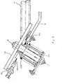
- Fig 1 shows the invented device seen from the side
- Fig 2 a detail thereof
- Fig 3 the activation device
- Figs 4 and 5 mounting details
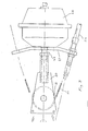
- Fig 6 yet another embodiment of the invention.
- the anti-skid device includes a chain-provided pulley 1 on which chain pieces 2 are passed.
- the chain-provided pulley 1 includes a circular ring 3 fastened to a disk 4.
- To the disk 4 is in turn the pieces 2 of chain fastened as well as the bearing housing 5.
- the chain-provided pulley 1 is via two ball bearings in the bearing housing 5 arranged on a bolt 6 that is fastened on an arm 7.
- the arm 7, which as well as the chain wheel 1 in Fig 1 is shown in the working position of the device is from a flat material so that some adaptions of the device can take place by bending or turning the arm 7.
- the arm 7 is fastened to a further bearing housing 8.
- the bearing housing 8 two ball bearings are arranged with a distance between them and on a pin 9.
- the pin 9 is in turn unturnably fastened to a plate 10 that in turn is welded to a tube 11.
- the tube 11 is held in two clamps 12 and 13 respectively by means of bolts 14 compressing the two slotted clamps 12 and 13.
- Both the clamps 12 and 13 are via angles 15 fastened to short threaded rod pieces 16.
- These threaded rods are then by means of internally threaded pipes or long nuts 17 fastened to the extending bolt ends 18 of the bolts holding the axle 19 of the vehicle wheel to its springs.
- the nuts 17 are locked by pins on the threaded rod pieces 16.
- This mounting is adaptable to the right and the left side respectively and allows by turning and displacement of the tube 11 in the clamps 12 and 13 a particularily good adaptioneven if the mounting circumstances varies. Furthermore by means of the angles an adjustment of the angle of the tube 11 relative the ground and thereby the longitudinal angle of the chain-provided pulley be achieved.
- the longitudinal angle of the chain-provided pulley is very essential since this to secure good function must be placed comparatively exactly relative the centre of the wheel and furthermore the chains must be thrown in in a rather precisely defined position over the ground in order to secure optimum use of the chains.
- a pulling wire 20 is arranged in order to on activation pull the arm 7 and thereby the chain-provided pulley 1 down to the working position.
- the pulling wire runs over a pulley 21 constituting a part of the bearing housing 8 and is fastened to the arm 7 at the wire fastening 22.
- a helicle spring 23 is arranged on the outer side of the bearing housing 8 and the helicle spring 23 has a rectangular cross section. The spring 23 is in one end fastened to the wire fastening 22 and in the other end to a washer 24 fastened to the axle pin or shaft 9.
- the washer 24 is held to the axle pin 9 only by means of the friction that results at the tightening of the bearings on the axle pin. In this way it is possible to tension the spring 23 to the desired amount. Due to the great number of turns of the spring that there are room for around the bearing housing it is possible for the the spring 23 to allow a return movement over a sufficiently great angle with a sufficient force. Due to the rectangular cross section there is no risk of the spring being closed by dirt.
- the pulley 21 is preferably arranged excentrically so that the force from the wire 20 receives its greatest torque arm when the chain-provided pulley 1 comes in contact with the vehicle wheel.
- the wire 20 is a bowdenwire the casing of which is fastened to the plate 20 in a fastening 25.
- the other end of the wire casing 26 is fastened to a plate 27.
- the wire 20 runs out in a new casing 26 to a similar anti-skid device at the other end of the vehicle wheel axle.
- the pressure air cylinder 28 On activation of the anti-skid device the pressure air cylinder 28 is activated and pushes out its push rod 29 which in turn means that by means of the pulley 31 the wire 20 is tensioned and pulls arms 7 on both sides of the vehicle. In this way it is possible to manage with only one pressure air cylinder, which means a saving.
- additional mounting holes for the axle 9 may be arranged in the plate 10, preferably placed on a line cutting the central line of the tube 11.
- the pressure air cylinder just anywhere on the vehicle where there is room.
- the parking position of the anti-skid device is in front of the wheel axle where in general most space exist.
- a mounting device similar to that described in the above embodiment also can be used together with a slightly different type of activation mechanism.
- an angled plate 52 to which a stub axle 53 is fastened and round which an arm 54 with accompanying spring 55 and pulley 56 is moveable.
- an arm is in the same way as in the above mentioned example fastened a pulley 57 over which wire 58 runs.
- the wire 58 goes from the pulley through a guide 68 in the end of the tube at the plate into the inner of the tube.
- the guide 68 is chamfered so that it gives an appropriate guiding of the wire and is preferably made of a low friction material (or at least the bushing through which the wire runs).
- the bellow 60 is of the type of a rolling bellow with a housing 62. When air with sufficient pressure is entered into the houseing the bellow goes out of the housing and gives a sufficiently long movement to turn the arm the necessary angle. As the pressurized air is removed the return spring of the arm draws bellow and arm back to the starting position.
- the tube provides the guiding of the rack and it is also possible to place the return spring inside the tube.
- the tube can of course also constitute the working cylindre of the hydraulic or air pressure device.
- Fig 1 is shown the working position and the parking position.
- the path that a chain-provided pulley will follow between those two positions will vary. And as a result it is possible to give the chain-provided pulley a curved path passing objects that would otherwise be in its way. This adjustment can be made without effecting the working position or the parking position.
- the only thing that is effected is the lateral angle of the pulley in its working position. This angle however has a very little influence on the position in which the chains are thrown in under a vehicle wheel.
Priority Applications (1)
| Application Number | Priority Date | Filing Date | Title |
|---|---|---|---|
| AT86850074T ATE52733T1 (de) | 1985-03-01 | 1986-02-28 | Gleitschutzeinrichtung. |
Applications Claiming Priority (2)
| Application Number | Priority Date | Filing Date | Title |
|---|---|---|---|
| SE8501021 | 1985-03-01 | ||
| SE8501021A SE447811B (sv) | 1985-03-01 | 1985-03-01 | Slirskydd |
Publications (2)
| Publication Number | Publication Date |
|---|---|
| EP0197902A1 true EP0197902A1 (fr) | 1986-10-15 |
| EP0197902B1 EP0197902B1 (fr) | 1990-05-16 |
Family
ID=20359333
Family Applications (1)
| Application Number | Title | Priority Date | Filing Date |
|---|---|---|---|
| EP86850074A Expired - Lifetime EP0197902B1 (fr) | 1985-03-01 | 1986-02-28 | Dispositif antidérapant |
Country Status (5)
| Country | Link |
|---|---|
| US (1) | US4800992A (fr) |
| EP (1) | EP0197902B1 (fr) |
| AT (1) | ATE52733T1 (fr) |
| DE (2) | DE3671196D1 (fr) |
| SE (1) | SE447811B (fr) |
Cited By (5)
| Publication number | Priority date | Publication date | Assignee | Title |
|---|---|---|---|---|
| DE3625677A1 (de) * | 1986-07-30 | 1988-03-24 | Rud Ketten Rieger & Dietz | Befestigungsvorrichtung fuer eine kraftfahrzeuggleitschutzvorrichtung |
| EP0334810A1 (fr) * | 1988-03-25 | 1989-09-27 | Beka St-Aubin SA | Dispositif de positionnement et de fixation d'un dispositif de chaîne à neige auxiliaire pour véhicule routier |
| US5236067A (en) * | 1987-06-26 | 1993-08-17 | Masao Inuzuka | Treading device for wheels |
| DE4215371A1 (de) * | 1992-05-08 | 1993-11-11 | Rud Ketten Rieger & Dietz | Gleitschutzvorrichtung für Kraftfahrzeuge |
| WO1999038714A1 (fr) * | 1998-01-29 | 1999-08-05 | Vbg Produkter Ab | Dispositif d'actionnement |
Families Citing this family (6)
| Publication number | Priority date | Publication date | Assignee | Title |
|---|---|---|---|---|
| SE459961C (sv) * | 1988-02-09 | 1990-10-25 | Goeran Toernebaeck | Anordning vid slirskydd |
| WO2001015947A1 (fr) * | 1999-08-27 | 2001-03-08 | Atikinson John H Jr | Ensemble de montage reglable permettant de deployer rapidement un systeme de chaines pour des vehicules a roues |
| US6651783B1 (en) | 2000-08-28 | 2003-11-25 | John H. Atkinson, Jr. | Adjustable mounting assembly for a rapidly-deployable ice chain system for wheeled vehicles |
| WO2005070737A1 (fr) * | 2004-01-13 | 2005-08-04 | Smith Fred P | Systeme d'asservissement electrique a couple limite permettant de deployer pour un vehicule un systeme de traction par chenille sur la neige |
| US7766387B1 (en) * | 2007-08-02 | 2010-08-03 | Onspot Of North America, Inc. | Anti-skid tire chain device |
| US10675914B2 (en) * | 2017-12-20 | 2020-06-09 | Dusawn Holdings LLC | Tire chains apparatus |
Citations (2)
| Publication number | Priority date | Publication date | Assignee | Title |
|---|---|---|---|---|
| US2543876A (en) | 1949-04-23 | 1951-03-06 | William P C Smith | Hydraulic power unit with fixed piston for producing oscillating motion |
| EP0162823A1 (fr) * | 1984-04-27 | 1985-11-27 | Onspot Ab | Dispositif antidérapant |
Family Cites Families (1)
| Publication number | Priority date | Publication date | Assignee | Title |
|---|---|---|---|---|
| US2277036A (en) * | 1941-03-10 | 1942-03-24 | Francis P Chaussee | Antiskid device |
-
1985
- 1985-03-01 SE SE8501021A patent/SE447811B/sv not_active IP Right Cessation
-
1986
- 1986-02-28 DE DE8686850074T patent/DE3671196D1/de not_active Expired - Lifetime
- 1986-02-28 DE DE198686850074T patent/DE197902T1/de active Pending
- 1986-02-28 EP EP86850074A patent/EP0197902B1/fr not_active Expired - Lifetime
- 1986-02-28 AT AT86850074T patent/ATE52733T1/de not_active IP Right Cessation
- 1986-10-14 US US06/918,536 patent/US4800992A/en not_active Expired - Fee Related
Patent Citations (2)
| Publication number | Priority date | Publication date | Assignee | Title |
|---|---|---|---|---|
| US2543876A (en) | 1949-04-23 | 1951-03-06 | William P C Smith | Hydraulic power unit with fixed piston for producing oscillating motion |
| EP0162823A1 (fr) * | 1984-04-27 | 1985-11-27 | Onspot Ab | Dispositif antidérapant |
Cited By (7)
| Publication number | Priority date | Publication date | Assignee | Title |
|---|---|---|---|---|
| DE3625677A1 (de) * | 1986-07-30 | 1988-03-24 | Rud Ketten Rieger & Dietz | Befestigungsvorrichtung fuer eine kraftfahrzeuggleitschutzvorrichtung |
| US5236067A (en) * | 1987-06-26 | 1993-08-17 | Masao Inuzuka | Treading device for wheels |
| EP0334810A1 (fr) * | 1988-03-25 | 1989-09-27 | Beka St-Aubin SA | Dispositif de positionnement et de fixation d'un dispositif de chaîne à neige auxiliaire pour véhicule routier |
| DE4215371A1 (de) * | 1992-05-08 | 1993-11-11 | Rud Ketten Rieger & Dietz | Gleitschutzvorrichtung für Kraftfahrzeuge |
| US5386888A (en) * | 1992-05-08 | 1995-02-07 | Rud-Kettenfabrik Rieger & Dietz Gmbh.U.Co. | Anti-skid device for motor vehicles |
| WO1999038714A1 (fr) * | 1998-01-29 | 1999-08-05 | Vbg Produkter Ab | Dispositif d'actionnement |
| US6409215B1 (en) | 1998-01-29 | 2002-06-25 | Vbg Produkter Ab | Operating device for anti-skid devices for vehicles |
Also Published As
| Publication number | Publication date |
|---|---|
| SE447811B (sv) | 1986-12-15 |
| US4800992A (en) | 1989-01-31 |
| DE3671196D1 (de) | 1990-06-21 |
| SE8501021L (sv) | 1986-09-02 |
| SE8501021D0 (sv) | 1985-03-01 |
| ATE52733T1 (de) | 1990-06-15 |
| EP0197902B1 (fr) | 1990-05-16 |
| DE197902T1 (de) | 1987-07-02 |
Similar Documents
| Publication | Publication Date | Title |
|---|---|---|
| EP0197902A1 (fr) | Dispositif antidérapant | |
| US4148498A (en) | Trailer hitch | |
| US4656888A (en) | Apparatus for vertical and axial adjustment of a steering wheel | |
| US6340165B1 (en) | Torsion axle and air bag vehicle suspension system | |
| US4198092A (en) | Seat suspension system | |
| JP3660025B2 (ja) | 可撓性フェンダー取り付け装置 | |
| US4955452A (en) | Locking apparatus for skid steer loader | |
| US20080143150A1 (en) | Manually Actuated Brake System for Manually Towable Vehicle | |
| US4027898A (en) | Level load leaf spring drop axle | |
| US6131481A (en) | Steering column | |
| US2879020A (en) | Equipment hose and flexible tube support | |
| EP0162823B2 (fr) | Dispositif antidérapant | |
| US4872728A (en) | Tilt-bed trailer | |
| EP3789620B1 (fr) | Dispositif de serrage | |
| US3993286A (en) | Low profile air jack | |
| GB1595848A (en) | Power rotary lawn mowers | |
| CA1309438C (fr) | Dispositif de chaine a neige auxiliaire pour vehicule routier | |
| US2815828A (en) | Automatic traction device for automobiles | |
| CA2037180A1 (fr) | Colonne de direction reglable | |
| US2242608A (en) | Tire scraping device | |
| US4870715A (en) | Caster including spring operated brake | |
| US4089387A (en) | Adjustable ratcheting wheel hub | |
| US4067592A (en) | Anti-jacknife apparatus | |
| US6766712B2 (en) | Steering column | |
| US6863305B2 (en) | Steering column |
Legal Events
| Date | Code | Title | Description |
|---|---|---|---|
| PUAI | Public reference made under article 153(3) epc to a published international application that has entered the european phase |
Free format text: ORIGINAL CODE: 0009012 |
|
| AK | Designated contracting states |
Kind code of ref document: A1 Designated state(s): AT BE CH DE FR GB IT LI LU NL SE |
|
| EL | Fr: translation of claims filed | ||
| TCNL | Nl: translation of patent claims filed | ||
| 17P | Request for examination filed |
Effective date: 19870205 |
|
| TCAT | At: translation of patent claims filed | ||
| DET | De: translation of patent claims | ||
| 17Q | First examination report despatched |
Effective date: 19870921 |
|
| GRAA | (expected) grant |
Free format text: ORIGINAL CODE: 0009210 |
|
| AK | Designated contracting states |
Kind code of ref document: B1 Designated state(s): AT BE CH DE FR GB IT LI LU NL SE |
|
| PG25 | Lapsed in a contracting state [announced via postgrant information from national office to epo] |
Ref country code: SE Effective date: 19900516 Ref country code: NL Effective date: 19900516 Ref country code: BE Effective date: 19900516 |
|
| REF | Corresponds to: |
Ref document number: 52733 Country of ref document: AT Date of ref document: 19900615 Kind code of ref document: T |
|
| ITF | It: translation for a ep patent filed |
Owner name: BARZANO' E ZANARDO MILANO S.P.A. |
|
| REF | Corresponds to: |
Ref document number: 3671196 Country of ref document: DE Date of ref document: 19900621 |
|
| ET | Fr: translation filed | ||
| NLV1 | Nl: lapsed or annulled due to failure to fulfill the requirements of art. 29p and 29m of the patents act | ||
| ITTA | It: last paid annual fee | ||
| PG25 | Lapsed in a contracting state [announced via postgrant information from national office to epo] |
Ref country code: LU Free format text: LAPSE BECAUSE OF NON-PAYMENT OF DUE FEES Effective date: 19910228 Ref country code: GB Effective date: 19910228 |
|
| PLBE | No opposition filed within time limit |
Free format text: ORIGINAL CODE: 0009261 |
|
| STAA | Information on the status of an ep patent application or granted ep patent |
Free format text: STATUS: NO OPPOSITION FILED WITHIN TIME LIMIT |
|
| 26N | No opposition filed | ||
| GBPC | Gb: european patent ceased through non-payment of renewal fee | ||
| ITPR | It: changes in ownership of a european patent |
Owner name: CESSIONE;VBG PRODUKTER AB |
|
| REG | Reference to a national code |
Ref country code: FR Ref legal event code: TP |
|
| REG | Reference to a national code |
Ref country code: CH Ref legal event code: PUE Owner name: VBG PRODUKTER AB |
|
| PGFP | Annual fee paid to national office [announced via postgrant information from national office to epo] |
Ref country code: AT Payment date: 19960209 Year of fee payment: 11 |
|
| PGFP | Annual fee paid to national office [announced via postgrant information from national office to epo] |
Ref country code: FR Payment date: 19960223 Year of fee payment: 11 |
|
| PGFP | Annual fee paid to national office [announced via postgrant information from national office to epo] |
Ref country code: CH Payment date: 19960227 Year of fee payment: 11 |
|
| PG25 | Lapsed in a contracting state [announced via postgrant information from national office to epo] |
Ref country code: LI Effective date: 19970228 Ref country code: CH Effective date: 19970228 Ref country code: AT Effective date: 19970228 |
|
| PGFP | Annual fee paid to national office [announced via postgrant information from national office to epo] |
Ref country code: DE Payment date: 19970929 Year of fee payment: 12 |
|
| REG | Reference to a national code |
Ref country code: CH Ref legal event code: PL |
|
| PG25 | Lapsed in a contracting state [announced via postgrant information from national office to epo] |
Ref country code: FR Effective date: 19971030 |
|
| REG | Reference to a national code |
Ref country code: FR Ref legal event code: ST |
|
| PG25 | Lapsed in a contracting state [announced via postgrant information from national office to epo] |
Ref country code: DE Free format text: LAPSE BECAUSE OF NON-PAYMENT OF DUE FEES Effective date: 19981103 |
|
| PG25 | Lapsed in a contracting state [announced via postgrant information from national office to epo] |
Ref country code: IT Free format text: LAPSE BECAUSE OF NON-PAYMENT OF DUE FEES;WARNING: LAPSES OF ITALIAN PATENTS WITH EFFECTIVE DATE BEFORE 2007 MAY HAVE OCCURRED AT ANY TIME BEFORE 2007. THE CORRECT EFFECTIVE DATE MAY BE DIFFERENT FROM THE ONE RECORDED. Effective date: 20050228 |