EP0197744A2 - Elektrostatisches Spritzgerät - Google Patents
Elektrostatisches Spritzgerät Download PDFInfo
- Publication number
- EP0197744A2 EP0197744A2 EP86302385A EP86302385A EP0197744A2 EP 0197744 A2 EP0197744 A2 EP 0197744A2 EP 86302385 A EP86302385 A EP 86302385A EP 86302385 A EP86302385 A EP 86302385A EP 0197744 A2 EP0197744 A2 EP 0197744A2
- Authority
- EP
- European Patent Office
- Prior art keywords
- spray
- electrode
- spraying apparatus
- housing
- electrodes
- Prior art date
- Legal status (The legal status is an assumption and is not a legal conclusion. Google has not performed a legal analysis and makes no representation as to the accuracy of the status listed.)
- Withdrawn
Links
Images


Classifications
-
- B—PERFORMING OPERATIONS; TRANSPORTING
- B05—SPRAYING OR ATOMISING IN GENERAL; APPLYING FLUENT MATERIALS TO SURFACES, IN GENERAL
- B05B—SPRAYING APPARATUS; ATOMISING APPARATUS; NOZZLES
- B05B5/00—Electrostatic spraying apparatus; Spraying apparatus with means for charging the spray electrically; Apparatus for spraying liquids or other fluent materials by other electric means
- B05B5/025—Discharge apparatus, e.g. electrostatic spray guns
- B05B5/053—Arrangements for supplying power, e.g. charging power
- B05B5/0533—Electrodes specially adapted therefor; Arrangements of electrodes
Definitions
- This invention relates to electrostatic spraying apparatus, particularly but not exclusively to inductively chargeable spraying apparatus of the kind used for agricultural and horticultural purposes. Electrostatic spraying apparatus also find industrial applications, for example for paint spraying.
- U.K. Patent Specification No.2140711 disclosed spraying apparatus comprising a spray nozzle, one or more electrodes disposed adjacent the path of spray emergent in use from the nozzle and a barrier adjacent the said one or more electrodes adapted to reduce contact of the spray with the electrodes, the barrier comprising one or more pointed protuberances arranged so that liquid draining in use from the barrier collects at said protuberances and is discharged from the latter by action of an electrostatic field.
- the present invention is concerned with improvements to the previously disclosed apparatus.
- spraying apparatus comprises a spray nozzle, one or more electrodes disposed adjacent the path of spray emergent in use from the nozzle and a barrier adjacent the said one or more electrodes adapted to reduce contact of the spray with the electrodes, the barrier including one or more pointed protuberances arranged so that liquid draining in use from the barrier collects at said protuberance and is discharged from the latter by the action of an electrostatic field, wherein the or each electrode is contained in a housing secured to the barrier by means of a support extending from a recess within the housing.
- the support is preferably spaced from and partially enclosed by the housing within the recess.
- the support may be provided with one or more baffles to impede any flow of liquid and prevent direct electrical tracking along the support.
- Location of the support within a recess in the electrode housing shelters the support from airborne droplets of spray or particles of dirt.
- the one or more baffles are also located within the recess.
- the baffles may be provided with sharp edges to further impede any flow of liquid and to enhance the electrostatic insulation of the electrode.
- the one or more electrodes have a greater dimension in a direction perpendicular to the direction of flow of the spray than in the direction of the flow of spray.
- the electrodes are preferably elongate across the direction of flow of the spray. This serves to ensure that the spray is charged across the full width thereof without recourse to an inefficiently large electrode area.
- the electrode housing may be adapted to maintain an unbroken stream of liquid between the electrode and the pointed protuberances. This serves to maintain a high electrical charge at the protuberances by conduction through an aqueous spray composition.
- the surfaces of the housing facing the spray is preferably generally flat or may be provided with drainage channels or ribs.
- the electrode assembly shown in Figures 1 to 5 comprises a spray nozzle 1 arranged to deliver a spray between two opposed electrode faces 2.
- the body of liquid is earthed, for example at the supply tank. Electrical charges induced on the spray due to the proximity of the electrodes cause mutual repulsion of the droplets of the spray, preventing formation of large drops. Adherence of the droplets to the surfaces of crops is enhanced. In addition the droplets are attracted to vertical or under-surfaces of foliage which might otherwise be sheltered from the spray. The charge induced by the electrodes has an opposite polarity to that of the electrodes. The finest droplets of the spray which tend to form a cloud are attracted to the electrodes and collect thereon.
- the electrodes 2 are each mounted in an insulating housing 3, composed,for example,of the plastics material marketed under the trade mark DELRIN.
- the lowest portions of the housing comprise two downwardly pointed projections 4, the remainder of the housing being generally rounded and not having pointed surfaces.
- the projections are positioned to provide an equal mass of redistributed material across the centre portion of the spray pattern. Liquid draining to the projections 4 is caused to disperse as droplets due to the action of the electric field at the points. Very high electrical stress at the projections has been found to be undesirable because the droplets released from the electrodes have an opposite charge to that induced in the main spray. It is detrimental to cause atomisation of the droplets from the electrodes to an extent beyond that required to render them airborne, since mixture of the oppositely charged droplets reduce the overall effectiveness of the apparatus.
- the electrode 2 is arranged to be located adjacent the region where the spray from the nozzle 1 breaks into droplets.
- the electrode is elongate in a direction across the width of the spray, usually generally perpendicular to the direction of movement of the liquid in a fan-shaped spray.
- the electrodes 2 may be curved to at least partially surround the spray formed by a cone, anvil or stream jet.
- Use of elongate electrode faces enables alternative nozzles to be employed, for example rotary atomisers.
- the spatial volume of the electrostatic field is increased.
- each electrode housing 3 The lower region of the front face 27 of each electrode housing 3 is flat to facilitate formation of an unbroken stream of liquid between the electrode 2 and the points 4, allowing electrical charge to reach the points by conduction. Drainage channels such as shallow grooves in the surface of the faces 27 may be provided to enhance conduction to the points 4.
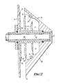
- Each electrode housing 3 is mounted upon a shroud 5 by means of an insulating support 6.
- the housing 3 is . hollow, having a recess 7 in the rear face, the support 6 extending into the recess and being secured to the housing at the deepest part thereof.
- the contact for the electrode 2 from the HT supply takes the form of a hollow rod shaped connector within an insulating tube 8 disposed within the support 6, through an aperture in the shroud 5. Connection of the HT supply to the electrode 2 immediately behind the face thereof is preferred to maximise the electric field at that point.
- the HT supply is preferably provided as an integral insulated assembly so that the contact with the electrode is the only point at which leakage can occur.
- the support 6 carries a plurality of disc like radial extensions 9 which serve to prevent flow of liquid along the support.
- the circumferences of the discs have sharp edges 10 which serve to cause a maximum impediment to flow of liquid and increase the electrical isolation of the electrode from the shroud.
- a plate-like or disc-like laminar portion 12 of the support abuts the shroud 5, this also having a pointed circumference.
- the interior of the recess 7 is also provided with an outwardly facing pointed annular formation 11 to enhance the electrical and mechanical isolation of the electrode.
- the laminar portion 12 and annular formation 11 both define annular gutters or channels 13,14 which serve to collect liquid draining along the surfaces of the shroud 6 or recess 7 respectively. Liquid collected in the gutters is conducted to the lowermost portions in the gutters from which it may drain to the pointed projections of the housing or shroud as the case may be. Flooding of the support 6 is thereby avoided.
- Alternative embodiments of this invention may include drainage ribs or channels upon the surface of the shrouds to direct flow of liquid away from the electrode supports.
- This feature the internal angle of the hollow recess, the external angles of the face of the electrode housing and the provision of the gutters 13 and 14 enables apparatus in accordance with this invention to be inclined at an angle to the vertical during use, rather than being confined to spraying in a vertical direction as shown in Figure 4. Spraying at any angle between the vertical and horizontal is possible. Spraying at an angle ahead or behind the direction of travel of spraying apparatus across the ground may be convenient to improve the degree of interception and coverage of under surfaces of foliage and vertical surfaces of plant stems which are connected to form a single assembly.
- the half portions 5 of the shroud each partially enclose a respective electrode, preventing deposition of spray on the latter.
- Each half portion of the shroud has two downwardly pointed projections 15 located outwardly of the projections 4 of the electrode housing. Liquid collected upon the shroud drains to the points 15 and is released back into the spray by action of the electrostatic field.
- the points 15 and 4 are disposed in spaced relation so that the liquid dispersed from them is evenly re-distributed within the spray pattern.
- the shroud is preferably arranged to closely surround the electrode housings in order to minimise the aerodynamic resistance of the apparatus, in order to facilitate use in air assisted spraying applications.
- the support portions 28 of the shrouds preferably occupy a minimal volume so that air flow through the spray head is not impeded.
- the shroud is arranged to be secured to the spray nozzle assembly by means of a supporting ring 16.
- a multiplicity of spraying heads as shown in Figures 1 to 4 may be disposed on a boom. Electrical connection between the heads may be conveniently achieved by means of a loom of modular connectors.
- Figure 5 illustrates a preferred arrangement in which the conductor 17 from the HT supply is connected to a plastics insulated terminal block 18 by means of a threaded connector 19. Connection to the two electrodes of a spray head is achieved via individual conductors 21 by means of two knurled threaded connectors 20 which may carry gold or silver plated terminal members. Each terminal is sealed within the terminal block 18 by a PTFE, AELRIN (Registered Trade Mark) or other plastics sleeve and a sealing ring.
- the terminal blocks 18 may be connected in series along a tubular boom 25 by means of clips or other fasterners 26 as shown in Figure 10. Similar terminal members 22 may be used for connection to the electrodes.
- Liquid supply to the spray nozzle is by means of a pipe (not shown) connected to an inlet 31.
- Conventional spraying apparatus may deliver 220 litres of aqueous solution per hectare at 300kP pressure through a 110° flat fan nozzle on a horizontal spray boom moving at a speed of about 2 ms
- the more efficient apparatus in accordance with this invention allows 100 to 110 litres per hectare to be delivered at a pressure of 400 kP using a 110° flat fan nozzle. Use of a higher pressure produces smaller droplets than has hitherto been possible. Furthermore, the head may be inclined by up to 45° without flooding the electrodes.
- Table 1 illustrates the superior performance of the present invention in comparison to that disclosed in our U.K.Patent Specification No. 2140711.
- Deposition of fluorescent tracers was measured in commercial crops of oil seed rape sprayed at two different growth stages. This work was supported by a trial carried out using a triazol plant growth regulator.
- Fluorescein was sprayed onto barley at the growth stage; GS 39-51 using three different application techniques - conventional hydraulic application at 200 1/ha, EX at 100 1/ha and rotary atomizer at 10 l/ha.
- This crop of thick barley was sprayed on 24/4/85 with a formulation of ioxynil, bromoxynil and mecoprop (Swipe 560SCW).
- Weeds were large and actively growing:- chickweed up to l5cm across, 38% ground cover, red dead- nettle, 4 whorls at 22/m 2 ; poppy, up to 8 leaves at 44/ m 2 ; and a few speedwell, pansy and forget-me-not.
- the full dosage was 4.5 1/ha.
Landscapes
- Electrostatic Spraying Apparatus (AREA)
- Catching Or Destruction (AREA)
Applications Claiming Priority (2)
| Application Number | Priority Date | Filing Date | Title |
|---|---|---|---|
| GB858508670A GB8508670D0 (en) | 1985-04-03 | 1985-04-03 | Electrostatic spraying apparatus |
| GB8508670 | 1985-04-03 |
Publications (2)
| Publication Number | Publication Date |
|---|---|
| EP0197744A2 true EP0197744A2 (de) | 1986-10-15 |
| EP0197744A3 EP0197744A3 (de) | 1987-03-04 |
Family
ID=10577121
Family Applications (1)
| Application Number | Title | Priority Date | Filing Date |
|---|---|---|---|
| EP86302385A Withdrawn EP0197744A3 (de) | 1985-04-03 | 1986-04-01 | Elektrostatisches Spritzgerät |
Country Status (3)
| Country | Link |
|---|---|
| US (1) | US4679735A (de) |
| EP (1) | EP0197744A3 (de) |
| GB (2) | GB8508670D0 (de) |
Cited By (2)
| Publication number | Priority date | Publication date | Assignee | Title |
|---|---|---|---|---|
| WO1991001811A1 (en) * | 1989-08-09 | 1991-02-21 | National Research Development Corporation | Electrostatic spraying |
| US11428787B2 (en) | 2016-10-25 | 2022-08-30 | Trinamix Gmbh | Detector for an optical detection of at least one object |
Families Citing this family (5)
| Publication number | Priority date | Publication date | Assignee | Title |
|---|---|---|---|---|
| CA1283676C (en) * | 1987-05-14 | 1991-04-30 | D. Gavin Semple | Crop sprayer shield |
| US5662267A (en) * | 1995-06-07 | 1997-09-02 | Dauenhauer Manufacturing, Inc. | Controlled atmosphere transfer system |
| US5865379A (en) * | 1997-05-12 | 1999-02-02 | Agco Corporation | Isolator for depending components on electrostatic field sprayer boom |
| ATE552917T1 (de) * | 2005-08-24 | 2012-04-15 | Brother Ind Ltd | Vorrichtung und verfahren zur erzeugung von schichten |
| US20220134370A1 (en) * | 2020-11-05 | 2022-05-05 | Digital Ally, Inc. | Electrostatic sprayer nozzle |
Family Cites Families (5)
| Publication number | Priority date | Publication date | Assignee | Title |
|---|---|---|---|---|
| FR2343513A1 (fr) * | 1976-03-08 | 1977-10-07 | Air Ind | Buse de poudrage electrostatique |
| CA1125358A (en) * | 1978-06-01 | 1982-06-08 | Ppg Industries, Inc. | High potential discharge control circuit including a resistive material coated electrode for induction-charging electrostatic spraying system |
| US4440349A (en) * | 1979-09-17 | 1984-04-03 | Ppg Industries, Inc. | Electrostatic spray gun having increased surface area from which fluid particles can be formed |
| GB2132917B (en) * | 1983-01-06 | 1986-05-21 | Nat Res Dev | Electrostatic spray head |
| GB2140711B (en) * | 1983-06-03 | 1986-02-19 | Spraycare Limited | Electrostatic spraying apparatus |
-
1985
- 1985-04-03 GB GB858508670A patent/GB8508670D0/en active Pending
-
1986
- 1986-04-01 GB GB8607923A patent/GB2173425B/en not_active Expired
- 1986-04-01 EP EP86302385A patent/EP0197744A3/de not_active Withdrawn
- 1986-04-02 US US06/847,238 patent/US4679735A/en not_active Expired - Fee Related
Cited By (2)
| Publication number | Priority date | Publication date | Assignee | Title |
|---|---|---|---|---|
| WO1991001811A1 (en) * | 1989-08-09 | 1991-02-21 | National Research Development Corporation | Electrostatic spraying |
| US11428787B2 (en) | 2016-10-25 | 2022-08-30 | Trinamix Gmbh | Detector for an optical detection of at least one object |
Also Published As
| Publication number | Publication date |
|---|---|
| US4679735A (en) | 1987-07-14 |
| EP0197744A3 (de) | 1987-03-04 |
| GB8508670D0 (en) | 1985-05-09 |
| GB2173425B (en) | 1989-06-28 |
| GB2173425A (en) | 1986-10-15 |
| GB8607923D0 (en) | 1986-05-08 |
Similar Documents
| Publication | Publication Date | Title |
|---|---|---|
| Law et al. | Electrostatic deposition of pesticide spray onto foliar targets of varying morphology | |
| Cooke et al. | Air-assisted spraying of arable crops, in relation to deposition, drift and pesticide performance | |
| Derksen et al. | Deposition and air speed patterns of air-carrier apple orchard sprayers | |
| US4735364A (en) | Electrostatic spray head | |
| US4679735A (en) | Electrostatic spraying apparatus | |
| Nordbo | Effects of nozzle size, travel speed and air assistance on deposition on artificial vertical and horizontal targets in laboratory experiments | |
| Hislop et al. | Deposition and biological efficacy of a fungicide applied in charged and uncharged sprays in cereal crops | |
| Singh et al. | Current status of electrostatic spraying technology for efficient crop protection | |
| Law | Electrostatically charged sprays | |
| Derksen et al. | Evaluation of handgun and broadcast systems for spray deposition in greenhouse poinsettia canopies | |
| Frankel | Pesticide application: technique and efficiency | |
| Palmer | Deposition patterns of small droplets applied to a tomato crop using the Ulvafan and two protoype electrostatic sprayers | |
| Dante et al. | Deposition studies of an electrostatic spinning disc sprayer | |
| Salyani et al. | Spray application variables affect air velocity and deposition characteristics of a tower sprayer | |
| Göhlich | Assessment of spray drift in sloping vineyards | |
| Rogers | The application of herbicides with ultra-small drops | |
| Singh et al. | Development and field evaluation of tractor mounted air assisted sprayer for cotton | |
| Taylor et al. | Preliminary field trials with 2, 4‐D ester, barban and tri‐allate applied in spray volumes of 5–20 l/ha | |
| Laryea et al. | Effect of fan speed and electrostatic charge on deposition of orchard canopy sprays | |
| Gordon et al. | Comparison of an air-assisted cross-flow sprayer with a conventional hydraulic sprayer for control of raspberry aphids by fenitrothion | |
| WO2021118490A1 (en) | A new unit to charge spray droplets with static electricity produced by turbo atomizers in the pesticide application | |
| Watson et al. | Air carrier technique for row crop spraying applications | |
| TW201636110A (zh) | 長距離靜電噴灑裝置 | |
| Sopp et al. | Deposition patterns and biological effectiveness of spray deposits on pot plants applied by the Ulvafan and three prototype electrostatic sprayers | |
| Svensson | Orchard spraying-deposition and air velocities as affected by air jet qualities |
Legal Events
| Date | Code | Title | Description |
|---|---|---|---|
| PUAI | Public reference made under article 153(3) epc to a published international application that has entered the european phase |
Free format text: ORIGINAL CODE: 0009012 |
|
| AK | Designated contracting states |
Kind code of ref document: A2 Designated state(s): AT BE CH DE FR IT LI LU NL SE |
|
| PUAL | Search report despatched |
Free format text: ORIGINAL CODE: 0009013 |
|
| AK | Designated contracting states |
Kind code of ref document: A3 Designated state(s): AT BE CH DE FR IT LI LU NL SE |
|
| 17P | Request for examination filed |
Effective date: 19870902 |
|
| 17Q | First examination report despatched |
Effective date: 19880825 |
|
| RAP1 | Party data changed (applicant data changed or rights of an application transferred) |
Owner name: INNOVO LIMITED |
|
| STAA | Information on the status of an ep patent application or granted ep patent |
Free format text: STATUS: THE APPLICATION IS DEEMED TO BE WITHDRAWN |
|
| 18D | Application deemed to be withdrawn |
Effective date: 19891222 |
|
| RIN1 | Information on inventor provided before grant (corrected) |
Inventor name: PAY, CHRISTOPHER CHARLES |