EP0197147A1 - Apparatus for shutting off gas - Google Patents
Apparatus for shutting off gas Download PDFInfo
- Publication number
- EP0197147A1 EP0197147A1 EP84903755A EP84903755A EP0197147A1 EP 0197147 A1 EP0197147 A1 EP 0197147A1 EP 84903755 A EP84903755 A EP 84903755A EP 84903755 A EP84903755 A EP 84903755A EP 0197147 A1 EP0197147 A1 EP 0197147A1
- Authority
- EP
- European Patent Office
- Prior art keywords
- shut
- gas
- microcomputer
- flow rate
- control unit
- Prior art date
- Legal status (The legal status is an assumption and is not a legal conclusion. Google has not performed a legal analysis and makes no representation as to the accuracy of the status listed.)
- Granted
Links
Images


Classifications
-
- F—MECHANICAL ENGINEERING; LIGHTING; HEATING; WEAPONS; BLASTING
- F23—COMBUSTION APPARATUS; COMBUSTION PROCESSES
- F23N—REGULATING OR CONTROLLING COMBUSTION
- F23N5/00—Systems for controlling combustion
- F23N5/24—Preventing development of abnormal or undesired conditions, i.e. safety arrangements
- F23N5/242—Preventing development of abnormal or undesired conditions, i.e. safety arrangements using electronic means
-
- F—MECHANICAL ENGINEERING; LIGHTING; HEATING; WEAPONS; BLASTING
- F23—COMBUSTION APPARATUS; COMBUSTION PROCESSES
- F23N—REGULATING OR CONTROLLING COMBUSTION
- F23N2223/00—Signal processing; Details thereof
- F23N2223/08—Microprocessor; Microcomputer
-
- F—MECHANICAL ENGINEERING; LIGHTING; HEATING; WEAPONS; BLASTING
- F23—COMBUSTION APPARATUS; COMBUSTION PROCESSES
- F23N—REGULATING OR CONTROLLING COMBUSTION
- F23N2231/00—Fail safe
- F23N2231/18—Detecting fluid leaks
-
- F—MECHANICAL ENGINEERING; LIGHTING; HEATING; WEAPONS; BLASTING
- F23—COMBUSTION APPARATUS; COMBUSTION PROCESSES
- F23N—REGULATING OR CONTROLLING COMBUSTION
- F23N2231/00—Fail safe
- F23N2231/20—Warning devices
-
- F—MECHANICAL ENGINEERING; LIGHTING; HEATING; WEAPONS; BLASTING
- F23—COMBUSTION APPARATUS; COMBUSTION PROCESSES
- F23N—REGULATING OR CONTROLLING COMBUSTION
- F23N2231/00—Fail safe
- F23N2231/20—Warning devices
- F23N2231/22—Warning devices using warning lamps
-
- F—MECHANICAL ENGINEERING; LIGHTING; HEATING; WEAPONS; BLASTING
- F23—COMBUSTION APPARATUS; COMBUSTION PROCESSES
- F23N—REGULATING OR CONTROLLING COMBUSTION
- F23N2235/00—Valves, nozzles or pumps
- F23N2235/12—Fuel valves
- F23N2235/14—Fuel valves electromagnetically operated
-
- F—MECHANICAL ENGINEERING; LIGHTING; HEATING; WEAPONS; BLASTING
- F23—COMBUSTION APPARATUS; COMBUSTION PROCESSES
- F23N—REGULATING OR CONTROLLING COMBUSTION
- F23N5/00—Systems for controlling combustion
- F23N5/18—Systems for controlling combustion using detectors sensitive to rate of flow of air or fuel
-
- Y—GENERAL TAGGING OF NEW TECHNOLOGICAL DEVELOPMENTS; GENERAL TAGGING OF CROSS-SECTIONAL TECHNOLOGIES SPANNING OVER SEVERAL SECTIONS OF THE IPC; TECHNICAL SUBJECTS COVERED BY FORMER USPC CROSS-REFERENCE ART COLLECTIONS [XRACs] AND DIGESTS
- Y10—TECHNICAL SUBJECTS COVERED BY FORMER USPC
- Y10T—TECHNICAL SUBJECTS COVERED BY FORMER US CLASSIFICATION
- Y10T137/00—Fluid handling
- Y10T137/1842—Ambient condition change responsive
- Y10T137/1915—Burner gas cutoff
-
- Y—GENERAL TAGGING OF NEW TECHNOLOGICAL DEVELOPMENTS; GENERAL TAGGING OF CROSS-SECTIONAL TECHNOLOGIES SPANNING OVER SEVERAL SECTIONS OF THE IPC; TECHNICAL SUBJECTS COVERED BY FORMER USPC CROSS-REFERENCE ART COLLECTIONS [XRACs] AND DIGESTS
- Y10—TECHNICAL SUBJECTS COVERED BY FORMER USPC
- Y10T—TECHNICAL SUBJECTS COVERED BY FORMER US CLASSIFICATION
- Y10T137/00—Fluid handling
- Y10T137/8158—With indicator, register, recorder, alarm or inspection means
- Y10T137/8225—Position or extent of motion indicator
- Y10T137/8242—Electrical
Definitions
- the present invention relates to a gas shut-off system for prevention of explosive accidents caused by town gas, liquefied petroleum gas, and the like, and in particular to a gas shut-off system comprising a control unit including a microcomputer whereby a shut-off valve is automatically closed in response to detection of abnormal conditions such as gas leak which is made by the aid of a gas flow rate sensor, and using a battery as a power supply.
- Town gas and LP gas are being widely used as an energy source for cooking, heating, hot-water supply, or the like. However, if there is any failure of handling, these gases explode and cause a great accident. On the other hand, recently high altitude and airtight houses have caused the neighborhood to suffer damage from the gas accident. Therefore, putting the safety provision and gas device for prevention of the gas accidents to practical use should be early achieved in view of social conditions.
- the flow rate pattern such as magnitude of gas flow rate and continuous time of flow rate become abnormal as compared with the normal conditions. Therefore, it is possible to previously prevent a wide range of gas accident including the accident with suicidal intent by automatically shutting off the gas main when the gas flow rate pattern becomes abnormal. Furthermore, the workability can be improved by combining a hardware therefor with a gas meter.
- the estimation of pattern of use, comparison with an abnormal pattern, and the like can be realized by means of a microcomputer.
- An object of the present invention is particularly to provide a long-life use for a battery used as a power supply in a system for previously preventing explosive accidents caused by gas such as town gas and LP gas used as an energy source for cooking, heating, hot-water supply in a house.
- a gas shut-off system according to the present invention includes a microcomputer programmed in terms of, for example, explosive limit to shut off the discharging of gas before the occurrence of gas explosion by the computation based on gas flow rate and discharge time. Also included in view of workability is a battery as a drive source. Therefore, a gas shut-off system according to the present invention is arranged to minimize the consumption of the battery and to provide a long-time use of the battery.
- a gas flow rate is detected by a flow rate sensor, and a microcomputer determines whether the flow rate pattern is normal or abnormal on the basis of the detection of the gas flow rate and actuates a sut-off valve to shut off the gas in response to the determination of abnormality.
- This system has greater ability for prevention of accidents as compared with conventional gas-accident preventing countermeasures.
- a harware is combined with the gas meter, resulting in making easy the provision into existing houses and improving the workability.
- This system comprises a lithium battery having excellent long-time realiability as a power source, a flow rate sensor having a reed switch, an exclusive CMOS 4-bit 1-chip microcomputer in which the consumption of current is low, an indicator including a LED and having an excellent visibility, and a self-hold type shut-off valve which matchs the characteristics of the lithium battery.
- the arrangement enables the system to be operated by one lithium battery over ten years.
- a battery has been selected as a power source of this system is as follows. Namely, in the case of use of the commercial power, it is required to provide a power cord between a power line and a gas meter, resulting in complex work and unsuitability for existing houses. Furthermore, when the power cord is intentionally or accidentally cut or when the supply of power to this system is stopped due to service interruption and the like, this system completely becomes unusable. Therefore, a system including a battery as a power source must be required.
- a flow rate sensor 2 which is means for measuring a flow rate is mounted on a gas meter 1 as shown in Fig. 1.
- a signal from the flow rate sensor 2 is applied to a control unit 3 for performing the determination of gas shut-off.
- the control unit 3 computes a gas flow rate and generates a cas shut-off signal when the gas flow rate meets predetermined conditions in terms of an abnormal flow rate.
- a shut-off valve 4 provided in a gas passage is actuated to close the gas passage.
- the control unit 3 is responsive to signals from abnormality sensors such as earthquake sensor and CO sensor to generate the shut-off signal to shut off the gas passage when,predetermined conditions are satisfied.
- the control unit 3 includes a microcomputer programmed to effect the determination of the gas shut-off, the microcomputer generating a shut-off signal to close the shut-off valve 4 when gas continuously flows for a predetermined time period.
- the shut-off signal is generated during a short time, whereas even if the flow rate is small, the determination of gas leak is made when the flow rate is not varied over a long time and the shut-off signal is generated, so that the discharge of gas is automatically stopped before reaching the explosive limit even if a closed space is filled with gas. This is effective for the abnormal condition that raw gas is continuously discharged with the cock of a gas device provided in a room being opened.
- an earthquake sensor is effective as means for previously preventing the leak of raw gas and explosive accident caused by the damage of the gas passage provided at downstream of the gas meter 1 or the connecting portion between the gas passage and the gas device due to earthquake
- a CO sensor is effective as means for detecting the permeation of carbon monoxide (CO) in a room due to incomplete combustion of a gas apparatus.
- the microcomputer of the control unit 3 can be set to a standby mode.
- the standby mode means the condition that the microcomputer waits for a specific signal, i.e., interruption signal. When the signal is received in the condition, it returns to a normal operating condition (operating mode).
- a specific signal i.e., interruption signal.
- operating mode a specific operating condition
- current required when the microcomputer is in the standby mode is approximately one several tenths as compared with current required in the operating mode, the value of the current being small. The reason is that most of functions are stopped in the standby mode.
- the control unit 3 receives an output of the flow rate sensor 2 arranged to count the reciprocating movements of the diaphragm of the gas meter and determines whether or not the gas flow rate periodically read is coincident with the gas aptitude use condition previously programmed. If the gas flow rate is coincident with the aptitude use condition, the measurement of flow rate is subsequently made. On the other hand, if it does not agree therewith because of abnormality, a gas shut-off signal is generated to shut off the shut-off valve 4.
- the comparison of the gas flow rate and the gas aptitude use condition is made for an extremely short time, and the microcomputer is in the standby mode except this comparison process, resulting in considerably preventing the consumption of the battery.
- the circuit including the control unit 3 is shown in detail in Fig. 2.
- a flow rate signal from the flow rate sensor 2 provided in the gas meter 1 is inputted through an interruption input terminal iNTl to the microcomputer 6 of the control unit 3.
- a signal indicative of abnormality from the abnormality sensor 5 is supplied through an abnormality sensor precessing circuit 7, an OR circuit 11, and an interruption input terminal iNT2 to the microcomputer 6.
- the abnormality sensor precessing circuit 7 comprises, for example, a chattering absorption circuit if the abnormality sensor 5 has a contact output.
- the shut-off output is applied from an output terminal ol through a shut-off valve driver 8 to the shut-off valve 4.
- the reference numeral 9 represents a return signal detecting circuit for detecting a return signal when the shut-off valve 4 is manually returned after the shut-off. Since a battery 13 is used as a system power source, A valve of one-shot self-hold type in which electromagnetic energy is not required for maintaining the the opening and closing conditions is employed as the shut-off valve 4.
- the shut-off valve 4 is of the one-shot self-hold type, for example, magnetic intensity of a permanent magnet is used for maintaining the shut-off valve 4 to the opening condition, and for setting the same to the closing condition, an one-shot current is applied to an electromagnetic coil so as to generate the magnetic intensity having polarity inversive to the polarity of the permanent magnet and the shut-off valve 4 is set to the closed condition by means of both the electromagnetic force and the force of a spring and then maintained to the closed condition by the aid of only the force of the spring. Setting the same again to the opening condition is achieved by an external force such as manual force. At this time, the electromagnetic coil generates counter-electromotive force.
- this counter-electromotive force developed across the electromagnetic coil of the shut-off valve can be used as the return signal.
- this counter-electromotive force is applied to a junction type N channel FET 10 making up the return signal detecting circuit 10, this FET 10 becomes OFF during the time period that the counter-electromotive force is below cut-off voltage.
- the output of the return signal detecting circuit 9 is supplied through the OR circuit 11 and the input terminal iNT2 to the microcomputer 6 and therefore only one OR circuit 11 can be used as a logic circuit.
- the reference numeral 19 represents a light emitting diode which is one kind of indicators for indicating that the shut-off valve 4 is in the shut-off condition, only one diode being used.
- the light emitting diode 19 is controlled through an output terminal Z55 of the microcomputer 6.
- the first output terminal 53 of the microcomputer 6 is set to a high level and the abnormality sensor precessing circuit 7 is in the operating condition, while the second output terminal 04 is set to a low level and the return signal detecting circuit 9 is in the non-operating condition. In these conditions, only an abnormality signal of the abnormality sensor 5 is inputted through the abnormality sensor precessing circuit 7 and the OR circuit 11 to the input terminal iNT2.
- the shut-off valve 4 When the shut-off valve 4 is closed in response to the occurrence of abnormality, the first output terminal o 3 of the microcomputer 6 becomes low level and the second output terminal 04 becomes high level, whereas the abnormality sensor processing circuit 7 is set to the non-operating condition and the return signal detecting circuit 9 is set to the operating condition.
- its electromagnetic coil In response to the return of the shut-off valve 4, its electromagnetic coil generates a counter-electromotive force, and when the counter-electromotive force is less than the cut-off voltage of the FET 10, the FET 10 is set to the off condition and its drain voltage becomes high level which is in turn applied through the OR circuit 11 to the input terminal iNT2.
- Fig. 3 is an illustration of the arrangement of the microcomputer 6.
- the microcomputer 6 has a standby mode as described above and the standby control is performed as follows.
- a stop command from a CPU stops the operation of a system clock generator 21, and therefore the system clock p is stopped to be generated and the microcomputer 6 is set to the standby mode. Thereafter, in response to the application of an interruption signal through the input terminal iNT2, the system clock generator 21 is again energized so that the microcomputer is returned to the operating mode.
- the power-supply current (IDD) in the standby mode is one several tenths as compared with the consumed current in the operating mode, this being very small.
- a timer 14 comprises a generator for oscillating a crystal 12, a divider for dividing the frequency of the generator, and a counter for counting time-base signals produced by the divider.
- Fig. 4 is a timing chart in terms of the circuit of Fig. 2. This timing chart represents the condition that the shut-off valve 4 is closed in response to the flow rate sensor 2 detcting that the gas flow becomes more than a predetermined flow rate.
- the shut-off valve 4 Before a time to, the shut-off valve 4 is not closed and therefore an output terminal 02 of the microcomputer 6 is a low level (Lo) and the flow rate sensor 2 is set to the active condition.
- the output of the output terminal 03 thereof is Hi
- the output of the output terminal o4 is Lo
- the abnormality sensor processing circuit 7 is set to the active condition
- the return signal detecting circuit 9 is set to the inhibited condition.
- the flow rate sensor 2 In response to the flow of gas, the flow rate sensor 2 is turned on and off in accordance with the gas flow rate.
- the input signal to the input terminal iNTl of the microcomputer 6 is changed from Lo to Hi and the microcomputer 6 allows an interruption to occur in response to the positive edge, and therefore the microcomputer is transferred from the standby mode to the operating mode.
- the microcomputer measures the time To between the previous iNTl interruption and the present interruption by means of a timer and then compares the measured time T ⁇ with a shut-off condition T F previously stored in a ROM. When T ⁇ > T F , determination is made wherein the gas flow rate is small and no shut-off is performed.
- the timer 14 is again energized and "STOP" command is again executed to be set to standby mode.
- the above precesses take a time T ON , and hereafter similar operations will be effected whenever the input terminal iNTI interruption occurs.
- the flow rate sensor is set from on to off and the input of the input terminal iNTl of the microcomputer 6 is varied from Hi to Lo. However, this negative edge results in no interruption.
- the flow rate sensor is set from off to on and therefore interruption occurs.
- the microcomputer 6 again makes the operating mode, because of T3 > T F , it is further set to the standby condition. Thereafter, when the gas flow rate is abnormally increased, the on and off of the flow rate sensor 2 become shorter.
- the microcomputer 6 set to the operating mode at a time t4. In this case, the determination is made as T2 > T F and therefore the microcomputer generates a shut-off signal through the output terminal o ⁇ 1 by a time period T OFF .
- the output of the output terminal o ⁇ 2 is set to Hi
- the output of the output terminal 63 is set to Lo
- the input terminal iNTl input from the flow rate sensor 2 is set to inhibited condition
- the abnormality sensor processing circuit 7 is set to inhibited condition.
- the outout terminal 04 is set to Hi and the return signal detecting circuit 9 is set to the active condition.
- the microcomputer 6 When the shut-off valve is manually returned at a time t7, a counter-electromotive force (negative voltage) is developed in the other coil.
- the FET 10 is turned off by the negative voltage and therefore a positive edge from Lo to Hi is inpuuted to the input terminal iNT2 of the microcomputer.
- the microcomputer 6 is set to the operating mode, confirms that the shut-off valve 4 has been returned, and returns the outputs of the output terminals o ⁇ 2, o ⁇ 3, and o ⁇ 4 to the conditions before the shut-off (before the time t4) at a time t8. Thereafter, the microcomputer 6 is set to the standby mode and waits for an interruption input (iNTl) from the flow rate sensor or an interruption input (iNT2) from the abnormality sensor.
- An output terminal 55 of the microcomputer 6 generates a signal for turning on and off the light emitting diode 19 after the time t6, that is, when the shut-off valve 4 is set to the closed condition.
- the turning on and off mode is employed for reducing the consumption of the battery for indication. Namely, if the duty for the lighting is 1/100, the average current consumption also becomes 1/100. This can be easily realized by, for example, lighting it by 16 msec at intervals of 1.6 second. Such an indication is easily visible.
- the microcomputer 6 When a return signal is inputted at the time t7, the microcomputer 6 outputs a lighting signal from the output terminal o ⁇ 5 by a time period longer than the lighting time (for example, 1 sec in the case of the lighting time of 16 msec), so that the fact that the return signal is inputted to the microcomputer 6 is indicated to the exterior. This is performed to indicate that the return operation has been accurately effected.
- Fig. 5 is a timing chart for understanding the conditions that the abnormality sensor 5 of Fig. 2 circuit is energized.
- the detection signal is inputted as an interruption signal to the input terminal iNT2 (time 12).
- the microcomputer is set from the standby mode to the operating mode to check a signal supplied to the input terminal iNT2.
- the shut-off condition that the shut-off is performed when abnormal state is continued over a predetermined time T is stored in a ROM of the microcomputer 6.
- the microcomputer 6 outputs a time TOFF shut-off signal from the output terminal o ⁇ 1.
- the operations after the time 13 are similar to the operations after the time t4 in Fig. 4.
- the shut-off is indicated by turning on and off the diode, whiel the return of the shut-off valve is indicated by lighting the same for a long time.
- the shut-off as indicated in Figs. 3 and 4, is roughly divided into shut-off caused by flow rate and shut-off caused by the abnormality sensor. Because the shut-off cause is different, it is desirable that the shut-off cause can be estimated in accordance with the indication. Therefore, the turning-on and off pattern for indicating the shut-off condition is made as shown in Fig. 6, for example. In Fig.
- the reference character a represents the turning on and off pattern of the shut-off caused by flow rate and character b designates the pattern of the shut-off caused by the external sensors.
- Such variations of the turning-on and off pattern can be easily realized in accordance with the program of the microcomputer 6.
- Fig. 6 in any cases, one lighting is performed at every period T L and the average currents required for the indication are equal to each other.
- a light emitting diode which has one package and enables to emit different two colors (generally, red and green) is available. If the diode is used, the output of the microcomputer 6 is increased by one and, in accordance with the pattern of Fig. 6b, when the shut-off is caused by flow rate, the indication can be made with green, and when it is caused by the external sensor, the indication can be made with red.
- the average current I DD is expressed as follows.
- I DS power-supply current in standby mode
- I DR power-supply current in operating mode 1
- T S 9T ON and , It will be seen from the above equation that the current I DD is about 1/5 as compared with I DR in the operating mode.
- the operating time period becomes five times. Furthermore, the FET 10 of the return signal detecting circuit 9 is set to the on condition because the voltage between its drain and gate is zero, and current does not flow between its drain and source because the output of the output terminal o ⁇ 4 is Lo, resulting in prevention of useless consumption. The reason is that it is not required to detect the return because the shut-off valve 4 is in the opening condition.
- the light emitting diode 19 is turned on and off, it is possible to reduce the average consumed current as compared with lighting.
- Fig. 7 illustrates another embodiment of the present invention.
- a logic circuit 15 receives a signal from the abnormality sensor 5 through the abnormality sensor - processing circuit 7 when the shut-off valve 4 is opened and then inputs the signal through the input terminal iNT2 to the microcomputer 6.
- a return signal from a return signal generating section 16 comprising a reed switch and so on is inputted through a return signal processing circuit 20 to the microcomputer 6.
- the outputs of the output terminals o3, o ⁇ 4 of the microcomputer 6 controls the abnormality sensor processing circuit 7 and the power supply of the return signal detecting circuit 9.
- the gate of the logic circuit 15 is controlled.
- the shut-off valve 4 when the shut-off valve 4 is opened, the output of the output terminal 03 of the microcomputer 6 is Hi, the output of the output terminal o4 thereof is Lo, an AND gate 15A is set to active condition, an AND gate 15B is set to inhibited condition, and the output of the abnormality sensor processing circuit 7 is inputted to the input terminal iNT2 of the microcomputer 6. Furthermore, when the shut-off valve 4 is closed, the outputs of the output terminals 53, ⁇ 4 of the microcomputer 6 become inverse, the AND gate 15A is set to the inhibited condition, the AND gate 15B is set to the active condition, and the return signal is inputted to the input terminal iNT2.
- a further embodiment of the present invention will be descrived with reference to Fig. 8.
- Fig. 8 arrangement does not include the avoce-described abnormality sensor 5.
- a control unit 3 includes a microcomputer 6 having a standby mode function.
- the microcomputer 6 is switched to the operating mode to the standby mode in accordancew with a software.
- the operating mode means the condition that the microcomputer 6 is nomaly operated, and in this case all functions are set to the operating conditions.
- the functions are almost set to the stop condition in the standby mode, the consumed current is reduced to about one several tenths as compared with that of the normal mode.
- the microcomputer 6 After the microcomputer 6 is once set to the standby mode, it maintains the standby mode until a return signal from a return signal generating section 16 is inputted to its interruption input terminal iNT2. In response to the input, the microcomputer is again set to the operating mode. Namely, as shown in Fog. 9, when the microcomputer 6 is in the operating mode, a shut-off signal is generated at a time tl. When a solenoid operated valve 4 is set to the closed condition at a time t2, the return signal generating section 16 is switched from on to off. When time goes to t3, that is, a predetermined time period is elapsed from the time tl, the generation of the shut-off signal is stopped.
- the microcomputer 6 is switched from the operating mode to the standby mode at a time t4.
- the solenoid operated valve 4 is set to the opened condition at a time t5
- the return signal generating section 16 is set to on and a return signal is inputted to the interruption input terminal iNT2 of the microcomputer 6, and therefore the microcomputer 6 is again switched from the standby mode to the operating mode to start to read a signal from the flow rate sensor 2.
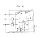
- FIG. 10 A still further embodiment of the present invention will be described with reference to Fig. 10.
- Fig. 10 arrangement the disconnection of the shut-off valve 4 can be detected.
- the refeence numeral 13 represents a battery and the on and off of a reed switch of a flow rate sensor 2 are converted into Hi and Lo voltage signals which are in turn inputted to the input terminal iNTl of the microcomputer 6.
- Numeral 16 designates a return signal generating section (which uses a reed switch), and a return signal processing circuit 20 converts the on and off of the reed switch 16 into Hi and Lo voltage signals and inputs them to an input terminal iNT3 of the microcomputer 6. In the shut-off condition, the reed switch 16 is off and the output of the return signal processing circuit 20 is Lo.
- Numeral 17 represents a disconnection detecting section which has a transistor 18.
- the microcomputer 6 receives a signal from the flow rate sensor 2, processes the signal in accordance with a predetermined process procedure, and checks whether or not the shut-off should be performed. If the shut-off condition is satisfied, a shut-off signal is outputted from the output terminal ol to a shut-off valve driver 8. In the process procedure, for example, it is performed to check whether or not the flow rate detected by the flow rate sensor 2 keeps a constant value over a predetermined time period. If it is over, the used time is longer than the normal use time of the device corresponding to the flow rate and such a condition is considered as an abnormality, and therefore a shut-off signal is outputted for a required time period.
- the input terminal iNT3 is set to Lo.
- the reed switch 16 of the return signal generating section is turned on and the output of the return signal processing circuit 20 becomes Hi, and thereby the microcomputer 6 can know the fact that the shut-off valve 4 has been set to the opened condition.
- the Hi signal is outputted periodically (for example, every 24 hours) from the output terminal 02 to energize the disconnection detecting section 17. This is performed using the internal timer 14 (Fig. 3) of the microcomputer 6.
- the output time period of the Hi signal is established so as not to operate the shut-off valve 4.
- the microcomputer 6 can check the presence or absence of the disconnection of the electromagnetic coil of the shut-off valve 4 by receiving the condition of the input terminal port i2 when Hi signal is outputted through the output terminal 02. If the electromagnetic coil of the shut-off valve 4 is normal, the Hi signal is inputted. If there is a disconnection, the Lo signal is inputted.
- a turning-on-and-off signal is outputted from the microcomputer 6 to an indicating section (light emitting diode 19) to inform an user.
- the turning on and off period is shortened to make possible to easily distinguish this turning on and off indication from the turning on and off indication at the time of shut-off.
- the present invention relates to a system which is more effective for gas explosion resulting from the separation of a rubber tube from a gas cock and the intentional opening of a gas cock and a fire and oxygen deficiency resulting from the forgetting of tuening-off of devices, as compared with conventional countermeasures for prevention of gas accidents.
- the system is combined with a gas meter and uses a battery having long time reliabil;ity as a power source. Therefore, it is possible to maintain high reliability for a long time and to be employed for existing houses.
Abstract
Description
- The present invention relates to a gas shut-off system for prevention of explosive accidents caused by town gas, liquefied petroleum gas, and the like, and in particular to a gas shut-off system comprising a control unit including a microcomputer whereby a shut-off valve is automatically closed in response to detection of abnormal conditions such as gas leak which is made by the aid of a gas flow rate sensor, and using a battery as a power supply.
- Town gas and LP gas are being widely used as an energy source for cooking, heating, hot-water supply, or the like. However, if there is any failure of handling, these gases explode and cause a great accident. On the other hand, recently high altitude and airtight houses have caused the neighborhood to suffer damage from the gas accident. Therefore, putting the safety provision and gas device for prevention of the gas accidents to practical use should be early achieved in view of social conditions.
- For prevention of the gas accidents, fuse cocks, reinforced gas hoses, town gas alarm devices, shut-off systems associated with alarm devices, and the like have been hitherto employed. These have not been spread to existing houses because of workability and are not necessarily effective for explosive accidents with suicidal intent which account for most of the accidents.
- Of the causes of gas accidents, short-time great amount discharge of raw gas resulting from the separation of a rubber tube from a gas cock or the intentional opening of a gas cock and abnormal heating or oxygen deficiency resulting from the forgetting of tuening-off of devices are important factors for the accidents, the accidents with suicidal intent relating to the former.
- In these accidents, the flow rate pattern such as magnitude of gas flow rate and continuous time of flow rate become abnormal as compared with the normal conditions. Therefore, it is possible to previously prevent a wide range of gas accident including the accident with suicidal intent by automatically shutting off the gas main when the gas flow rate pattern becomes abnormal. Furthermore, the workability can be improved by combining a hardware therefor with a gas meter.
- The estimation of pattern of use, comparison with an abnormal pattern, and the like can be realized by means of a microcomputer.
- An object of the present invention is particularly to provide a long-life use for a battery used as a power supply in a system for previously preventing explosive accidents caused by gas such as town gas and LP gas used as an energy source for cooking, heating, hot-water supply in a house. A gas shut-off system according to the present invention includes a microcomputer programmed in terms of, for example, explosive limit to shut off the discharging of gas before the occurrence of gas explosion by the computation based on gas flow rate and discharge time. Also included in view of workability is a battery as a drive source. Therefore, a gas shut-off system according to the present invention is arranged to minimize the consumption of the battery and to provide a long-time use of the battery.
- In this system, a gas flow rate is detected by a flow rate sensor, and a microcomputer determines whether the flow rate pattern is normal or abnormal on the basis of the detection of the gas flow rate and actuates a sut-off valve to shut off the gas in response to the determination of abnormality. This system has greater ability for prevention of accidents as compared with conventional gas-accident preventing countermeasures. In addition, a harware is combined with the gas meter, resulting in making easy the provision into existing houses and improving the workability.
- This system comprises a lithium battery having excellent long-time realiability as a power source, a flow rate sensor having a reed switch, an exclusive CMOS 4-bit 1-chip microcomputer in which the consumption of current is low, an indicator including a LED and having an excellent visibility, and a self-hold type shut-off valve which matchs the characteristics of the lithium battery. The arrangement enables the system to be operated by one lithium battery over ten years.
- The reason that a battery has been selected as a power source of this system is as follows. Namely, in the case of use of the commercial power, it is required to provide a power cord between a power line and a gas meter, resulting in complex work and unsuitability for existing houses. Furthermore, when the power cord is intentionally or accidentally cut or when the supply of power to this system is stopped due to service interruption and the like, this system completely becomes unusable. Therefore, a system including a battery as a power source must be required.
- However, the duration of service of the battery is limited and therefore it is required to exchange the battery with a new one when the voltage is dropped due to consumption. Period of the battery exchange as long as possible is desirable for user because of reduction of labor.
-
- Fig. 1 is an illustration of the principle arrangement of a gas shut-off system according to an embodiment of the present invention;
- Fig. 2 is a detailed circuit diagram of Fig. 1 arrangement;
- Fig. 3 is a diagram showing the microcomputer of Fig. 2 circuit;
- Figs. 4 and 5 are wave form charts for understanding the operation of the circuit of Fig. 2;
- Fig. 6 is a wave form chart for understanding the operation of an indicator;
- Fig. 7 is a diagram illustrating a gas shut-off system according to another embodiment of the present invention;
- Fig. 8 is a diagram showing a gas shut-off system according to a further embodiment of the present invention;
- Fig. 9 is wave form chart for undestanding the operation of the system of Fig. 8; and
- Fig. 10 is a diagram illustrating a gas shut-off system according to a still further emboidment of the present invention.
- An embodiment of the present invention will be hereinbelow described with reference to the drawings.
- A
flow rate sensor 2 which is means for measuring a flow rate is mounted on a gas meter 1 as shown in Fig. 1. A signal from theflow rate sensor 2 is applied to acontrol unit 3 for performing the determination of gas shut-off. Thecontrol unit 3 computes a gas flow rate and generates a cas shut-off signal when the gas flow rate meets predetermined conditions in terms of an abnormal flow rate. In response to the gas shut-off signal, a shut-offvalve 4 provided in a gas passage is actuated to close the gas passage. Furthermore, thecontrol unit 3 is responsive to signals from abnormality sensors such as earthquake sensor and CO sensor to generate the shut-off signal to shut off the gas passage when,predetermined conditions are satisfied. - The
control unit 3 includes a microcomputer programmed to effect the determination of the gas shut-off, the microcomputer generating a shut-off signal to close the shut-offvalve 4 when gas continuously flows for a predetermined time period. Namely, in the case of abnormally great flow rate, the shut-off signal is generated during a short time, whereas even if the flow rate is small, the determination of gas leak is made when the flow rate is not varied over a long time and the shut-off signal is generated, so that the discharge of gas is automatically stopped before reaching the explosive limit even if a closed space is filled with gas. This is effective for the abnormal condition that raw gas is continuously discharged with the cock of a gas device provided in a room being opened. - Furthermore, an earthquake sensor is effective as means for previously preventing the leak of raw gas and explosive accident caused by the damage of the gas passage provided at downstream of the gas meter 1 or the connecting portion between the gas passage and the gas device due to earthquake, while a CO sensor is effective as means for detecting the permeation of carbon monoxide (CO) in a room due to incomplete combustion of a gas apparatus. These sensors are provided as an abnormality sensor.
- The microcomputer of the
control unit 3 can be set to a standby mode. The standby mode means the condition that the microcomputer waits for a specific signal, i.e., interruption signal. When the signal is received in the condition, it returns to a normal operating condition (operating mode). Generally, current required when the microcomputer is in the standby mode is approximately one several tenths as compared with current required in the operating mode, the value of the current being small. The reason is that most of functions are stopped in the standby mode. - The
control unit 3 receives an output of theflow rate sensor 2 arranged to count the reciprocating movements of the diaphragm of the gas meter and determines whether or not the gas flow rate periodically read is coincident with the gas aptitude use condition previously programmed. If the gas flow rate is coincident with the aptitude use condition, the measurement of flow rate is subsequently made. On the other hand, if it does not agree therewith because of abnormality, a gas shut-off signal is generated to shut off the shut-offvalve 4. The comparison of the gas flow rate and the gas aptitude use condition is made for an extremely short time, and the microcomputer is in the standby mode except this comparison process, resulting in considerably preventing the consumption of the battery. - The circuit including the
control unit 3 is shown in detail in Fig. 2. - A flow rate signal from the
flow rate sensor 2 provided in the gas meter 1 is inputted through an interruption input terminal iNTl to themicrocomputer 6 of thecontrol unit 3. A signal indicative of abnormality from theabnormality sensor 5 is supplied through an abnormality sensor precessingcircuit 7, anOR circuit 11, and an interruption input terminal iNT2 to themicrocomputer 6. The abnormality sensor precessingcircuit 7 comprises, for example, a chattering absorption circuit if theabnormality sensor 5 has a contact output. The shut-off output is applied from an output terminal ol through a shut-offvalve driver 8 to the shut-offvalve 4. The reference numeral 9 represents a return signal detecting circuit for detecting a return signal when the shut-offvalve 4 is manually returned after the shut-off. Since abattery 13 is used as a system power source, A valve of one-shot self-hold type in which electromagnetic energy is not required for maintaining the the opening and closing conditions is employed as the shut-offvalve 4. - In order that the shut-off
valve 4 is of the one-shot self-hold type, for example, magnetic intensity of a permanent magnet is used for maintaining the shut-offvalve 4 to the opening condition, and for setting the same to the closing condition, an one-shot current is applied to an electromagnetic coil so as to generate the magnetic intensity having polarity inversive to the polarity of the permanent magnet and the shut-offvalve 4 is set to the closed condition by means of both the electromagnetic force and the force of a spring and then maintained to the closed condition by the aid of only the force of the spring. Setting the same again to the opening condition is achieved by an external force such as manual force. At this time, the electromagnetic coil generates counter-electromotive force. Therefore, this counter-electromotive force developed across the electromagnetic coil of the shut-off valve can be used as the return signal. When this counter-electromotive force is applied to a junction typeN channel FET 10 making up the returnsignal detecting circuit 10, thisFET 10 becomes OFF during the time period that the counter-electromotive force is below cut-off voltage. The output of the return signal detecting circuit 9 is supplied through theOR circuit 11 and the input terminal iNT2 to themicrocomputer 6 and therefore only one ORcircuit 11 can be used as a logic circuit. Thereference numeral 19 represents a light emitting diode which is one kind of indicators for indicating that the shut-offvalve 4 is in the shut-off condition, only one diode being used. Thelight emitting diode 19 is controlled through an output terminal Z55 of themicrocomputer 6. - The operation made in accordance with such an arrangement will be described hereinbelow.
- When the shut-off
valve 4 is set to the opening condition, the first output terminal 53 of themicrocomputer 6 is set to a high level and the abnormalitysensor precessing circuit 7 is in the operating condition, while thesecond output terminal 04 is set to a low level and the return signal detecting circuit 9 is in the non-operating condition. In these conditions, only an abnormality signal of theabnormality sensor 5 is inputted through the abnormalitysensor precessing circuit 7 and theOR circuit 11 to the input terminal iNT2. When the shut-offvalve 4 is closed in response to the occurrence of abnormality, the firstoutput terminal o microcomputer 6 becomes low level and thesecond output terminal 04 becomes high level, whereas the abnormalitysensor processing circuit 7 is set to the non-operating condition and the return signal detecting circuit 9 is set to the operating condition. In response to the return of the shut-offvalve 4, its electromagnetic coil generates a counter-electromotive force, and when the counter-electromotive force is less than the cut-off voltage of theFET 10, theFET 10 is set to the off condition and its drain voltage becomes high level which is in turn applied through theOR circuit 11 to the input terminal iNT2. - Fig. 3 is an illustration of the arrangement of the
microcomputer 6. Themicrocomputer 6 has a standby mode as described above and the standby control is performed as follows. - A stop command from a CPU stops the operation of a
system clock generator 21, and therefore the system clock p is stopped to be generated and themicrocomputer 6 is set to the standby mode. Thereafter, in response to the application of an interruption signal through the input terminal iNT2, thesystem clock generator 21 is again energized so that the microcomputer is returned to the operating mode. The power-supply current (IDD) in the standby mode is one several tenths as compared with the consumed current in the operating mode, this being very small. - A
timer 14 comprises a generator for oscillating acrystal 12, a divider for dividing the frequency of the generator, and a counter for counting time-base signals produced by the divider. - Fig. 4 is a timing chart in terms of the circuit of Fig. 2. This timing chart represents the condition that the shut-off
valve 4 is closed in response to theflow rate sensor 2 detcting that the gas flow becomes more than a predetermined flow rate. - Before a time to, the shut-off
valve 4 is not closed and therefore anoutput terminal 02 of themicrocomputer 6 is a low level (Lo) and theflow rate sensor 2 is set to the active condition. The output of theoutput terminal 03 thereof is Hi, the output of the output terminal o4 is Lo, the abnormalitysensor processing circuit 7 is set to the active condition, and the return signal detecting circuit 9 is set to the inhibited condition. These conditions are maintained until the shut-off of the shut-offvalve 4. - In response to the flow of gas, the
flow rate sensor 2 is turned on and off in accordance with the gas flow rate. When the flow rate sensor is turned on at the time to, the input signal to the input terminal iNTl of themicrocomputer 6 is changed from Lo to Hi and themicrocomputer 6 allows an interruption to occur in response to the positive edge, and therefore the microcomputer is transferred from the standby mode to the operating mode. The microcomputer measures the time To between the previous iNTl interruption and the present interruption by means of a timer and then compares the measured time Tø with a shut-off condition TF previously stored in a ROM. When Tø > TF, determination is made wherein the gas flow rate is small and no shut-off is performed. Thetimer 14 is again energized and "STOP" command is again executed to be set to standby mode. The above precesses take a time TON, and hereafter similar operations will be effected whenever the input terminal iNTI interruption occurs. At a time t2, the flow rate sensor is set from on to off and the input of the input terminal iNTl of themicrocomputer 6 is varied from Hi to Lo. However, this negative edge results in no interruption. At a time t3, the flow rate sensor is set from off to on and therefore interruption occurs. Although themicrocomputer 6 again makes the operating mode, because of T3 > TF, it is further set to the standby condition. Thereafter, when the gas flow rate is abnormally increased, the on and off of theflow rate sensor 2 become shorter. This is detected by themicrocomputer 6 set to the operating mode at a time t4. In this case, the determination is made as T2 > TF and therefore the microcomputer generates a shut-off signal through the output terminal o̅1 by a time period TOFF. When the generation of the shut-off signal is terminated at a time t5, the output of the output terminal o̅2 is set to Hi, the output of the output terminal 63 is set to Lo, the input terminal iNTl input from theflow rate sensor 2 is set to inhibited condition, and the abnormalitysensor processing circuit 7 is set to inhibited condition. After the termination of these processes, at a time t6, theoutout terminal 04 is set to Hi and the return signal detecting circuit 9 is set to the active condition. The reason that these processes is not performed at the time t5 but performed at the time t6 elapsed by an appropriate time from the time t5, is to prevent a counter-electromotive force (negative voltage) produced at the time t5 by the turning-off of current passing through the coil of the shut-off valve from being detected as a return signal. Thereafter, themicrocomputer 6 is set to the standby condition and then waits for an interruption input (iNT2) from the return signal detecting circuit 9. - When the shut-off valve is manually returned at a time t7, a counter-electromotive force (negative voltage) is developed in the other coil. The
FET 10 is turned off by the negative voltage and therefore a positive edge from Lo to Hi is inpuuted to the input terminal iNT2 of the microcomputer. Thereby, themicrocomputer 6 is set to the operating mode, confirms that the shut-offvalve 4 has been returned, and returns the outputs of the output terminals o̅2, o̅3, and o̅4 to the conditions before the shut-off (before the time t4) at a time t8. Thereafter, themicrocomputer 6 is set to the standby mode and waits for an interruption input (iNTl) from the flow rate sensor or an interruption input (iNT2) from the abnormality sensor. - An output terminal 55 of the
microcomputer 6 generates a signal for turning on and off thelight emitting diode 19 after the time t6, that is, when the shut-offvalve 4 is set to the closed condition. The turning on and off mode is employed for reducing the consumption of the battery for indication. Namely, if the duty for the lighting is 1/100, the average current consumption also becomes 1/100. This can be easily realized by, for example, lighting it by 16 msec at intervals of 1.6 second. Such an indication is easily visible. When a return signal is inputted at the time t7, themicrocomputer 6 outputs a lighting signal from the output terminal o̅5 by a time period longer than the lighting time (for example, 1 sec in the case of the lighting time of 16 msec), so that the fact that the return signal is inputted to themicrocomputer 6 is indicated to the exterior. This is performed to indicate that the return operation has been accurately effected. - Fig. 5 is a timing chart for understanding the conditions that the
abnormality sensor 5 of Fig. 2 circuit is energized. - When abnormality has been detected by the
abnormality sensor 5, the detection signal is inputted as an interruption signal to the input terminal iNT2 (time 12). In this case, the microcomputer is set from the standby mode to the operating mode to check a signal supplied to the input terminal iNT2. the shut-off condition that the shut-off is performed when abnormal state is continued over a predetermined time T is stored in a ROM of themicrocomputer 6. At a time t13, since the abnormal state has been continued by the predetermined time TA, themicrocomputer 6 outputs a time TOFF shut-off signal from the output terminal o̅1. The operations after thetime 13 are similar to the operations after the time t4 in Fig. 4. - Here, a detailed description is made in terms of the indication by the
light emitting diode 19. Only one light emitting diode is used for indicating the shut-off and return. The shut-off is indicated by turning on and off the diode, whiel the return of the shut-off valve is indicated by lighting the same for a long time. The shut-off, as indicated in Figs. 3 and 4, is roughly divided into shut-off caused by flow rate and shut-off caused by the abnormality sensor. Because the shut-off cause is different, it is desirable that the shut-off cause can be estimated in accordance with the indication. Therefore, the turning-on and off pattern for indicating the shut-off condition is made as shown in Fig. 6, for example. In Fig. 6, the reference character a represents the turning on and off pattern of the shut-off caused by flow rate and character b designates the pattern of the shut-off caused by the external sensors. Such variations of the turning-on and off pattern can be easily realized in accordance with the program of themicrocomputer 6. In Fig. 6, in any cases, one lighting is performed at every period TL and the average currents required for the indication are equal to each other. - Now, a light emitting diode which has one package and enables to emit different two colors (generally, red and green) is available. If the diode is used, the output of the
microcomputer 6 is increased by one and, in accordance with the pattern of Fig. 6b, when the shut-off is caused by flow rate, the indication can be made with green, and when it is caused by the external sensor, the indication can be made with red. - With the shut-off
valve 4 being opned, only when theflow rate sensor 2 is varied from on to off and theabnormality sensor 5 detects abnormality, themicrocomputer 6 is set to the operating mode. Furthermore, even if it is in the operating condition, after the termination of predetermined processes, it is again returned to the standby mode. Therefore, the time period T set to the standby mode is longer than the time period TON set to the operating condition. The average current IDD is expressed as follows.


FET 10 of the return signal detecting circuit 9 is set to the on condition because the voltage between its drain and gate is zero, and current does not flow between its drain and source because the output of the output terminal o̅4 is Lo, resulting in prevention of useless consumption. The reason is that it is not required to detect the return because the shut-offvalve 4 is in the opening condition. - On the other hand, with the shut-off
valve 4 being closed, the output of the output terminal o̅2 of themicrocomputer 6 is Hi and the output of the output terminal o̅3 thereof is Lo, and therefore even if the flow rate sensor is turned on or theabnormality sensor 5 is set to abnormal condition, current does not flow through them, resulting in no uselessness. - In addition, because the
light emitting diode 19 is turned on and off, it is possible to reduce the average consumed current as compared with lighting. - Fig. 7 illustrates another embodiment of the present invention. A
logic circuit 15 receives a signal from theabnormality sensor 5 through the abnormality sensor -processing circuit 7 when the shut-offvalve 4 is opened and then inputs the signal through the input terminal iNT2 to themicrocomputer 6. On the other hand, when the shut-offvalve 4 is closed, a return signal from a returnsignal generating section 16 comprising a reed switch and so on is inputted through a returnsignal processing circuit 20 to themicrocomputer 6. In the embodiment of Fig. 2, the outputs of the output terminals o3, o̅4 of themicrocomputer 6 controls the abnormalitysensor processing circuit 7 and the power supply of the return signal detecting circuit 9. However, in the embodiment of Fig. 6, the gate of thelogic circuit 15 is controlled. That is, when the shut-offvalve 4 is opened, the output of theoutput terminal 03 of themicrocomputer 6 is Hi, the output of the output terminal o4 thereof is Lo, an AND gate 15A is set to active condition, an AND gate 15B is set to inhibited condition, and the output of the abnormalitysensor processing circuit 7 is inputted to the input terminal iNT2 of themicrocomputer 6. Furthermore, when the shut-offvalve 4 is closed, the outputs of the output terminals 53, õ4 of themicrocomputer 6 become inverse, the AND gate 15A is set to the inhibited condition, the AND gate 15B is set to the active condition, and the return signal is inputted to the input terminal iNT2. - A further embodiment of the present invention will be descrived with reference to Fig. 8. Fig. 8 arrangement does not include the avoce-described
abnormality sensor 5. Acontrol unit 3 includes amicrocomputer 6 having a standby mode function. Themicrocomputer 6 is switched to the operating mode to the standby mode in accordancew with a software. Here, The operating mode means the condition that themicrocomputer 6 is nomaly operated, and in this case all functions are set to the operating conditions. On the other hand, since the functions are almost set to the stop condition in the standby mode, the consumed current is reduced to about one several tenths as compared with that of the normal mode. After themicrocomputer 6 is once set to the standby mode, it maintains the standby mode until a return signal from a returnsignal generating section 16 is inputted to its interruption input terminal iNT2. In response to the input, the microcomputer is again set to the operating mode. Namely, as shown in Fog. 9, when themicrocomputer 6 is in the operating mode, a shut-off signal is generated at a time tl. When a solenoid operatedvalve 4 is set to the closed condition at a time t2, the returnsignal generating section 16 is switched from on to off. When time goes to t3, that is, a predetermined time period is elapsed from the time tl, the generation of the shut-off signal is stopped. Thereafter, themicrocomputer 6 is switched from the operating mode to the standby mode at a time t4. When the solenoid operatedvalve 4 is set to the opened condition at a time t5, the returnsignal generating section 16 is set to on and a return signal is inputted to the interruption input terminal iNT2 of themicrocomputer 6, and therefore themicrocomputer 6 is again switched from the standby mode to the operating mode to start to read a signal from theflow rate sensor 2. - A still further embodiment of the present invention will be described with reference to Fig. 10. In Fig. 10 arrangement, the disconnection of the shut-off
valve 4 can be detected. - In Fig. 10, the
refeence numeral 13 represents a battery and the on and off of a reed switch of aflow rate sensor 2 are converted into Hi and Lo voltage signals which are in turn inputted to the input terminal iNTl of themicrocomputer 6.Numeral 16 designates a return signal generating section (which uses a reed switch), and a returnsignal processing circuit 20 converts the on and off of thereed switch 16 into Hi and Lo voltage signals and inputs them to an input terminal iNT3 of themicrocomputer 6. In the shut-off condition, thereed switch 16 is off and the output of the returnsignal processing circuit 20 is Lo.Numeral 17 represents a disconnection detecting section which has atransistor 18. - The
microcomputer 6 receives a signal from theflow rate sensor 2, processes the signal in accordance with a predetermined process procedure, and checks whether or not the shut-off should be performed. If the shut-off condition is satisfied, a shut-off signal is outputted from the output terminal ol to a shut-offvalve driver 8. In the process procedure, for example, it is performed to check whether or not the flow rate detected by theflow rate sensor 2 keeps a constant value over a predetermined time period. If it is over, the used time is longer than the normal use time of the device corresponding to the flow rate and such a condition is considered as an abnormality, and therefore a shut-off signal is outputted for a required time period. In the shut-off condition, since thereed switch 16 of the return signal generating section is off, the input terminal iNT3 is set to Lo. Next, when the shut-offvalve 4 is manually opened, thereed switch 16 of the return signal generating section is turned on and the output of the returnsignal processing circuit 20 becomes Hi, and thereby themicrocomputer 6 can know the fact that the shut-offvalve 4 has been set to the opened condition. The Hi signal is outputted periodically (for example, every 24 hours) from theoutput terminal 02 to energize thedisconnection detecting section 17. This is performed using the internal timer 14 (Fig. 3) of themicrocomputer 6. The output time period of the Hi signal is established so as not to operate the shut-offvalve 4. When the output of the output terminal 32 becomes Hi, voltage is applied to the emitter of thetransistor 18. If the electromagentic coil of the shut-offvalve 4 is normal without disconnection, a base current Ib flows so that thetransistor 18 is turned on. Therefore, the collector voltage Ec of thetransistor 18 becomes Hi and is inputted to an input terminal i2 of themicrocomputer 6. Themicrocomputer 6 can check the presence or absence of the disconnection of the electromagnetic coil of the shut-offvalve 4 by receiving the condition of the input terminal port i2 when Hi signal is outputted through theoutput terminal 02. If the electromagnetic coil of the shut-offvalve 4 is normal, the Hi signal is inputted. If there is a disconnection, the Lo signal is inputted. When disconnected, a turning-on-and-off signal is outputted from themicrocomputer 6 to an indicating section (light emitting diode 19) to inform an user. In this case, the turning on and off period is shortened to make possible to easily distinguish this turning on and off indication from the turning on and off indication at the time of shut-off. - As understood from the above, the present invention relates to a system which is more effective for gas explosion resulting from the separation of a rubber tube from a gas cock and the intentional opening of a gas cock and a fire and oxygen deficiency resulting from the forgetting of tuening-off of devices, as compared with conventional countermeasures for prevention of gas accidents.
- Furthermore, the system is combined with a gas meter and uses a battery having long time reliabil;ity as a power source. Therefore, it is possible to maintain high reliability for a long time and to be employed for existing houses.
-
- 1.....gas meter
- 2.....flow rate sensor
- 3.....control unit
- 4.....shut-off valve
- 5.....abnormality sensor
- 6.....microcomputer
- 7.....abnormality sensor processing circuit
- 8.....shut-off valve driver
- 9.....return signal detecting circuit
- 10....junction type N channel FET
- 11....OR circuit
- 12....crystal
- 13....battery
- 14....timer
- 15....logic circuit
- 15A...AND gate
- 15B...AND gate
- 16....return signal generating section
- 17....disconnection detecting section
- 18....transistor
- 19....light emitting diode
- 20....return signal processing circuit
- 21....system clock generator
- iNT...input terminal
- o.....output terminal
Claims (7)
Applications Claiming Priority (1)
| Application Number | Priority Date | Filing Date | Title |
|---|---|---|---|
| PCT/JP1984/000477 WO1986002431A1 (en) | 1984-10-11 | 1984-10-11 | Apparatus for shutting off gas |
Publications (3)
| Publication Number | Publication Date |
|---|---|
| EP0197147A1 true EP0197147A1 (en) | 1986-10-15 |
| EP0197147A4 EP0197147A4 (en) | 1988-09-07 |
| EP0197147B1 EP0197147B1 (en) | 1991-05-29 |
Family
ID=13818426
Family Applications (1)
| Application Number | Title | Priority Date | Filing Date |
|---|---|---|---|
| EP84903755A Expired - Lifetime EP0197147B1 (en) | 1984-10-11 | 1984-10-11 | Apparatus for shutting off gas |
Country Status (5)
| Country | Link |
|---|---|
| US (1) | US4787410A (en) |
| EP (1) | EP0197147B1 (en) |
| DE (1) | DE3484654D1 (en) |
| HK (1) | HK5896A (en) |
| WO (1) | WO1986002431A1 (en) |
Cited By (7)
| Publication number | Priority date | Publication date | Assignee | Title |
|---|---|---|---|---|
| WO1989000682A1 (en) * | 1987-07-14 | 1989-01-26 | Dan-Taet, Odense A/S | Gas-tightness control system |
| GB2246226A (en) * | 1990-07-21 | 1992-01-22 | Stoves Ltd | Noxious fluid safety system |
| GB2251506A (en) * | 1990-12-14 | 1992-07-08 | Platon Flow Control | Leak detector |
| FR2729455A1 (en) * | 1995-01-16 | 1996-07-19 | Bhiki Eric Ambroise | Gas leak detection and alarm system |
| WO1998002857A1 (en) * | 1996-07-11 | 1998-01-22 | Eric Bhiki | Protection system against gas leakage |
| US5908980A (en) * | 1995-06-24 | 1999-06-01 | Tae Gu City Gas Co. Ltd | Integrated safety control system for user's gas facility and gas leakage recognizing method |
| EP2251602A1 (en) * | 2008-02-26 | 2010-11-17 | Panasonic Corporation | Gas shut-off device and alarm-compatible system meter |
Families Citing this family (16)
| Publication number | Priority date | Publication date | Assignee | Title |
|---|---|---|---|---|
| US5126934A (en) * | 1989-06-09 | 1992-06-30 | Smart House, L.P. | Gas distribution system |
| DE4123236C1 (en) * | 1991-07-13 | 1992-08-27 | Hans 5013 Elsdorf De Jobst | Alarm and security system for building with gas pipes - has throughflow indicator in by=pass line and with non-return valve operating switch for magnetic valve and optical signal generator |
| US5419358A (en) * | 1993-08-02 | 1995-05-30 | Francis Myrtil | Gas monitoring system for a boiler |
| US5722448A (en) * | 1996-08-08 | 1998-03-03 | Dourado; Mizael F. | Gas line automatic cut off valve |
| US6123093A (en) * | 1998-04-30 | 2000-09-26 | D'antonio Consultants International, Inc. | System for controlling fluid flow |
| US6045352A (en) * | 1998-06-25 | 2000-04-04 | Nicholson; Leroy E. | Carbon monoxide automatic furnace shutdown system |
| US6269829B1 (en) * | 2000-09-29 | 2001-08-07 | Industrial Technology Research Institute | Integrated gas meter |
| US6788209B2 (en) * | 2002-03-22 | 2004-09-07 | Br&T Technology Development Corporation | Automatic emergency shut-off system for delivery transports |
| JP2004309374A (en) * | 2003-04-09 | 2004-11-04 | Fuji Electric Fa Components & Systems Co Ltd | Fluid meter |
| JP5111780B2 (en) * | 2006-05-08 | 2013-01-09 | サーパス工業株式会社 | Valve control device and flow controller |
| JP4858453B2 (en) * | 2008-01-24 | 2012-01-18 | パナソニック株式会社 | Gas shut-off device |
| GB2477776A (en) * | 2010-02-12 | 2011-08-17 | Haven Ltd | Valve with leak detector |
| JP5789162B2 (en) * | 2011-09-28 | 2015-10-07 | 京セラ株式会社 | Energy management system, gas meter and energy management device |
| ES2736278T3 (en) * | 2013-03-15 | 2019-12-27 | Altria Client Services Llc | System and method of obtaining topographic data of smoking |
| JP6462395B2 (en) * | 2015-02-12 | 2019-01-30 | 矢崎エナジーシステム株式会社 | Gas meter and alarm |
| KR102203286B1 (en) * | 2020-06-24 | 2021-01-14 | 엠피아주식회사 | Self-powered gas valve wireless remote open/close monitoring system |
Citations (2)
| Publication number | Priority date | Publication date | Assignee | Title |
|---|---|---|---|---|
| FR2257080A1 (en) * | 1974-01-08 | 1975-08-01 | Sud Ouest Ste Nationale Gaz | |
| DE3242750A1 (en) * | 1982-11-19 | 1984-05-24 | Helmut 6436 Schenklengsfeld Pfromm | Discharge stop for liquid, solid or gaseous substances from the corresponding supply network |
Family Cites Families (12)
| Publication number | Priority date | Publication date | Assignee | Title |
|---|---|---|---|---|
| US3307613A (en) * | 1965-09-03 | 1967-03-07 | Honeywell Inc | Control apparatus |
| JPS5546560B2 (en) * | 1972-09-07 | 1980-11-25 | ||
| JPS5338944B2 (en) * | 1973-02-21 | 1978-10-18 | ||
| US3955186A (en) * | 1974-05-17 | 1976-05-04 | Compugraphic Corporation | Character image generation apparatus and CRT phototypesetting system |
| DE2550061A1 (en) * | 1975-11-07 | 1977-05-12 | Knorr Bremse Gmbh | DEVICE FOR FLOW LIMITING |
| JPS5847014B2 (en) * | 1976-10-12 | 1983-10-20 | 株式会社山武 | Fluid leak alarm device |
| US4262687A (en) * | 1977-11-11 | 1981-04-21 | Iida Sankyo Co., Ltd. | Electromagnetic valve security device for fuel supplies |
| JPS57129973A (en) * | 1981-02-03 | 1982-08-12 | Mitsubishi Electric Corp | System to shut off gas supply |
| JPS57144365A (en) * | 1981-02-28 | 1982-09-06 | Matsushita Electric Works Ltd | Gas stopping device |
| JPS5885130A (en) * | 1981-11-16 | 1983-05-21 | Mitsubishi Electric Corp | Device for detecting leakage of fluid |
| JPS58115339A (en) * | 1981-12-29 | 1983-07-09 | Fujitsu Ltd | Detector for water leakage |
| JPS59110986A (en) * | 1982-12-14 | 1984-06-27 | Matsushita Electric Ind Co Ltd | Gas cut-off display device |
-
1984
- 1984-10-11 WO PCT/JP1984/000477 patent/WO1986002431A1/en active IP Right Grant
- 1984-10-11 US US06/878,990 patent/US4787410A/en not_active Expired - Lifetime
- 1984-10-11 DE DE8484903755T patent/DE3484654D1/en not_active Expired - Lifetime
- 1984-10-11 EP EP84903755A patent/EP0197147B1/en not_active Expired - Lifetime
-
1996
- 1996-01-11 HK HK5896A patent/HK5896A/en not_active IP Right Cessation
Patent Citations (2)
| Publication number | Priority date | Publication date | Assignee | Title |
|---|---|---|---|---|
| FR2257080A1 (en) * | 1974-01-08 | 1975-08-01 | Sud Ouest Ste Nationale Gaz | |
| DE3242750A1 (en) * | 1982-11-19 | 1984-05-24 | Helmut 6436 Schenklengsfeld Pfromm | Discharge stop for liquid, solid or gaseous substances from the corresponding supply network |
Non-Patent Citations (1)
| Title |
|---|
| See also references of WO8602431A1 * |
Cited By (9)
| Publication number | Priority date | Publication date | Assignee | Title |
|---|---|---|---|---|
| WO1989000682A1 (en) * | 1987-07-14 | 1989-01-26 | Dan-Taet, Odense A/S | Gas-tightness control system |
| GB2246226A (en) * | 1990-07-21 | 1992-01-22 | Stoves Ltd | Noxious fluid safety system |
| GB2246226B (en) * | 1990-07-21 | 1995-02-01 | Stoves Ltd | Improvements in or relating to safety systems |
| GB2251506A (en) * | 1990-12-14 | 1992-07-08 | Platon Flow Control | Leak detector |
| FR2729455A1 (en) * | 1995-01-16 | 1996-07-19 | Bhiki Eric Ambroise | Gas leak detection and alarm system |
| US5908980A (en) * | 1995-06-24 | 1999-06-01 | Tae Gu City Gas Co. Ltd | Integrated safety control system for user's gas facility and gas leakage recognizing method |
| WO1998002857A1 (en) * | 1996-07-11 | 1998-01-22 | Eric Bhiki | Protection system against gas leakage |
| EP2251602A1 (en) * | 2008-02-26 | 2010-11-17 | Panasonic Corporation | Gas shut-off device and alarm-compatible system meter |
| EP2251602A4 (en) * | 2008-02-26 | 2011-06-29 | Panasonic Corp | Gas shut-off device and alarm-compatible system meter |
Also Published As
| Publication number | Publication date |
|---|---|
| EP0197147A4 (en) | 1988-09-07 |
| US4787410A (en) | 1988-11-29 |
| WO1986002431A1 (en) | 1986-04-24 |
| HK5896A (en) | 1996-01-19 |
| EP0197147B1 (en) | 1991-05-29 |
| DE3484654D1 (en) | 1991-07-04 |
Similar Documents
| Publication | Publication Date | Title |
|---|---|---|
| EP0197147A1 (en) | Apparatus for shutting off gas | |
| JPH1137459A (en) | Gas meter with gas shutoff valve | |
| JP2611167B2 (en) | Gas shut-off device for gas-using equipment | |
| JPH08128914A (en) | Leak detection device | |
| JP3558430B2 (en) | Gas meter with battery voltage monitoring device | |
| JPH10260070A (en) | Gas shut-off control device | |
| JPH09106490A (en) | Emergency gas shut-off device | |
| JPH0943024A (en) | Gas meter | |
| JPH0444150B2 (en) | ||
| JPH0239120Y2 (en) | ||
| KR950012162B1 (en) | Hot water boiler | |
| JPS6030409B2 (en) | gas safety device | |
| JP3132607B2 (en) | Control device | |
| JPH1194613A (en) | Device for identifying kind of gas, gas meter incorporating the same, and gas combustor | |
| JP2502548B2 (en) | Centralized gas meter reading device | |
| JP2545607Y2 (en) | Gas leak alarm shutoff device | |
| JP2002310753A (en) | Fuel gage | |
| JPS5888538A (en) | Fuel interception control device | |
| JPS6359048B2 (en) | ||
| JPS63119781A (en) | Gas blocking valve apparatus | |
| JP2995419B2 (en) | Automatic gas shut-off device | |
| JPH0450727A (en) | Gas meter with safety function | |
| JPH11230794A (en) | Lp gas measuring device | |
| JPH04336397A (en) | Gas leak detection device | |
| JPH05282574A (en) | Shut-off control unit |
Legal Events
| Date | Code | Title | Description |
|---|---|---|---|
| PUAI | Public reference made under article 153(3) epc to a published international application that has entered the european phase |
Free format text: ORIGINAL CODE: 0009012 |
|
| 17P | Request for examination filed |
Effective date: 19860609 |
|
| AK | Designated contracting states |
Kind code of ref document: A1 Designated state(s): DE FR GB |
|
| A4 | Supplementary search report drawn up and despatched |
Effective date: 19880907 |
|
| 17Q | First examination report despatched |
Effective date: 19890216 |
|
| GRAA | (expected) grant |
Free format text: ORIGINAL CODE: 0009210 |
|
| AK | Designated contracting states |
Kind code of ref document: B1 Designated state(s): DE FR GB |
|
| ET | Fr: translation filed | ||
| REF | Corresponds to: |
Ref document number: 3484654 Country of ref document: DE Date of ref document: 19910704 |
|
| PLBE | No opposition filed within time limit |
Free format text: ORIGINAL CODE: 0009261 |
|
| STAA | Information on the status of an ep patent application or granted ep patent |
Free format text: STATUS: NO OPPOSITION FILED WITHIN TIME LIMIT |
|
| 26N | No opposition filed | ||
| REG | Reference to a national code |
Ref country code: GB Ref legal event code: 746 Effective date: 19960820 |
|
| REG | Reference to a national code |
Ref country code: GB Ref legal event code: IF02 |
|
| PGFP | Annual fee paid to national office [announced via postgrant information from national office to epo] |
Ref country code: FR Payment date: 20031003 Year of fee payment: 20 |
|
| PGFP | Annual fee paid to national office [announced via postgrant information from national office to epo] |
Ref country code: GB Payment date: 20031008 Year of fee payment: 20 |
|
| PGFP | Annual fee paid to national office [announced via postgrant information from national office to epo] |
Ref country code: DE Payment date: 20031023 Year of fee payment: 20 |
|
| PG25 | Lapsed in a contracting state [announced via postgrant information from national office to epo] |
Ref country code: GB Free format text: LAPSE BECAUSE OF EXPIRATION OF PROTECTION Effective date: 20041010 |
|
| REG | Reference to a national code |
Ref country code: GB Ref legal event code: PE20 |