EP0196717A1 - Method and apparatus for making glass bodies - Google Patents
Method and apparatus for making glass bodies Download PDFInfo
- Publication number
- EP0196717A1 EP0196717A1 EP86200483A EP86200483A EP0196717A1 EP 0196717 A1 EP0196717 A1 EP 0196717A1 EP 86200483 A EP86200483 A EP 86200483A EP 86200483 A EP86200483 A EP 86200483A EP 0196717 A1 EP0196717 A1 EP 0196717A1
- Authority
- EP
- European Patent Office
- Prior art keywords
- suspension
- membrane
- green body
- produced
- porous
- Prior art date
- Legal status (The legal status is an assumption and is not a legal conclusion. Google has not performed a legal analysis and makes no representation as to the accuracy of the status listed.)
- Granted
Links
Images

Classifications
-
- C—CHEMISTRY; METALLURGY
- C03—GLASS; MINERAL OR SLAG WOOL
- C03B—MANUFACTURE, SHAPING, OR SUPPLEMENTARY PROCESSES
- C03B19/00—Other methods of shaping glass
- C03B19/12—Other methods of shaping glass by liquid-phase reaction processes
-
- C—CHEMISTRY; METALLURGY
- C03—GLASS; MINERAL OR SLAG WOOL
- C03B—MANUFACTURE, SHAPING, OR SUPPLEMENTARY PROCESSES
- C03B37/00—Manufacture or treatment of flakes, fibres, or filaments from softened glass, minerals, or slags
- C03B37/01—Manufacture of glass fibres or filaments
- C03B37/012—Manufacture of preforms for drawing fibres or filaments
- C03B37/014—Manufacture of preforms for drawing fibres or filaments made entirely or partially by chemical means, e.g. vapour phase deposition of bulk porous glass either by outside vapour deposition [OVD], or by outside vapour phase oxidation [OVPO] or by vapour axial deposition [VAD]
- C03B37/016—Manufacture of preforms for drawing fibres or filaments made entirely or partially by chemical means, e.g. vapour phase deposition of bulk porous glass either by outside vapour deposition [OVD], or by outside vapour phase oxidation [OVPO] or by vapour axial deposition [VAD] by a liquid phase reaction process, e.g. through a gel phase
-
- Y—GENERAL TAGGING OF NEW TECHNOLOGICAL DEVELOPMENTS; GENERAL TAGGING OF CROSS-SECTIONAL TECHNOLOGIES SPANNING OVER SEVERAL SECTIONS OF THE IPC; TECHNICAL SUBJECTS COVERED BY FORMER USPC CROSS-REFERENCE ART COLLECTIONS [XRACs] AND DIGESTS
- Y10—TECHNICAL SUBJECTS COVERED BY FORMER USPC
- Y10S—TECHNICAL SUBJECTS COVERED BY FORMER USPC CROSS-REFERENCE ART COLLECTIONS [XRACs] AND DIGESTS
- Y10S65/00—Glass manufacturing
- Y10S65/15—Nonoxygen containing chalogenides
- Y10S65/16—Optical filament or fiber treatment with fluorine or incorporating fluorine in final product
-
- Y—GENERAL TAGGING OF NEW TECHNOLOGICAL DEVELOPMENTS; GENERAL TAGGING OF CROSS-SECTIONAL TECHNOLOGIES SPANNING OVER SEVERAL SECTIONS OF THE IPC; TECHNICAL SUBJECTS COVERED BY FORMER USPC CROSS-REFERENCE ART COLLECTIONS [XRACs] AND DIGESTS
- Y10—TECHNICAL SUBJECTS COVERED BY FORMER USPC
- Y10S—TECHNICAL SUBJECTS COVERED BY FORMER USPC CROSS-REFERENCE ART COLLECTIONS [XRACs] AND DIGESTS
- Y10S65/00—Glass manufacturing
- Y10S65/90—Drying, dehydration, minimizing oh groups
-
- Y—GENERAL TAGGING OF NEW TECHNOLOGICAL DEVELOPMENTS; GENERAL TAGGING OF CROSS-SECTIONAL TECHNOLOGIES SPANNING OVER SEVERAL SECTIONS OF THE IPC; TECHNICAL SUBJECTS COVERED BY FORMER USPC CROSS-REFERENCE ART COLLECTIONS [XRACs] AND DIGESTS
- Y10—TECHNICAL SUBJECTS COVERED BY FORMER USPC
- Y10S—TECHNICAL SUBJECTS COVERED BY FORMER USPC CROSS-REFERENCE ART COLLECTIONS [XRACs] AND DIGESTS
- Y10S65/00—Glass manufacturing
- Y10S65/901—Liquid phase reaction process
Definitions
- the invention relates to a process for the manufacture of vitreous bodies, in which a porous green body is formed from the starting material for the vitreous body in the form of a suspension with a highly disperse solid component and this is then cleaned and sintered.
- the invention further relates to devices for carrying out such a method and to the use of the glass bodies produced by the method according to the invention.
- the method mentioned at the outset is particularly suitable for producing preforms for optical waveguides.
- a porous green body is produced from highly disperse SiO 2 glass particles, after which this porous green body is initially in, for example, a chlorine-containing atmosphere at temperatures in the range from 600 to 900 ° C is cleaned.
- the sintering to compact, transparent glass then takes place at temperatures in the region of 1500 ° C; the level of the sintering temperature depends on the size of the SiO 2 ponds and the homogeneity of the green body.
- the invention has for its object to provide a method and devices for the production of high-purity glass bodies, with which a green body is obtained which is porous enough that it can be cleaned well in an intermediate heating step in a gas atmosphere reacting with existing impurities, but it does has such a high compaction that the subsequent sintering step can take place without additional compaction measures of the green body.
- a negative pressure or an excess pressure is generated in the device. This has the advantage that a relatively high separation rate of the solids content of the suspension is achieved.
- a suspension is used as the starting material for the vitreous body, the SiO 2 particles having a diameter in the range from 10 to 500 nm, preferably 15 to 100 nm, with an average particle diameter of 40 nm with a solid:
- Water to weight ratio of 1: 1 to 1: 2 contains the advantage that green bodies can be obtained with an advantageously high density, as is required for the later sintering process of the green body
- an ionogenic additive is added to the suspension, which shifts the pH of the suspension into the basic range (pH ⁇ 10), preferably an ammonium compound in an amount of 0.1 to 5 % By weight, based on the solids content of the suspension, is used.
- This additive is volatile and can be removed without residue from the green body in a subsequent cleaning and heating step, so that quartz glass bodies of very high purity can be produced.
- an ammonium compound for example NH 3 in aqueous solution, green bodies of relatively high strength are achieved since they have a cross-linking effect, with gel formation occurring at the contact points of two SiO 2 primary particles, for example at a suspension temperature of 20 ° C.
- a pH Value ⁇ 10 Si0 2 is of the order of about 100 ppm in solution and is excreted at the contact points and thus forms a bridge layer. If an ionogenic additive such as NH 4 F is used in aqueous solution, fluorine doping of the starting material can be achieved to reduce the refractive index.
- aqueous solution fluorine doping of the starting material can be achieved to reduce the refractive index.
- Such glasses are suitable as cladding glasses for optical waveguides.
- a layered body is deposited on the membrane by depositing several layers in succession from differently doped suspensions.
- the first suspension is removed from the device and the deposition process is continued with a second suspension, for example doped differently from the first suspension.
- the present method is therefore particularly suitable for producing preforms for optical waveguides which have a step profile of the refractive index exhibit. It is also possible to produce an optical waveguide with a W profile by incorporating an intermediate layer with a lower refractive index, which is obtained by using a suspension with appropriate doping.
- Dopants for changing the refractive index of a vitreous body are known to the person skilled in the art, for example Ge0 2 or Al 2 O 3 is used for increasing the refractive index and for lowering the refractive index B20 3 or fluorine.
- the present method it is also possible to deposit a large number of substances to produce a quartz glass body with graded doped layers with an approximately continuous refractive index curve.
- a porous green body made of the starting material for the glass body to be produced is used as the membrane.
- layers can be produced from the solids content of the suspension with a comfraction which is different from the comfraction used for the production of such a membrane.
- the shrinkage behavior of a body depends on the comfraction; if an already sintered body made of the starting material for vitreous bodies is used as the membrane, it is possible to adapt the shrinkage behavior of the membrane and the layer to be deposited thereon.
- the green body is deposited on a membrane, the separating surface of which is lined with a lining, in particular made of plastic, which has a porosity of the average particle diameter of the solids content of the suspension, in particular a plastic membrane preferably made of polyethylene with a pore diameter in the Is used in the range of 10 to 20 microns, there is the advantage that even larger green bodies can be easily removed.
- a hydrophilic plastic is preferably used for the feed
- the advantages that can be achieved with the invention further consist, in particular, in that, for the manufacture of glass bodies, in particular preforms for optical waveguides, green bodies can be obtained with very little outlay on equipment, which on the one hand are porous enough that impurities are effectively removed in a heated gas atmosphere which, on the other hand, have such a high density and "homogeneity that they can be sintered into high-purity glass bodies without further intermediate processing steps, such as hot isostatic pressing.
- green bodies can be produced which have a cross-section deviating from a circular cross-section, for example angular pipes or rods or also hollow bodies of any shape.
- the separated green bodies can be dried without cracks and result in transparent, true-to-size after the cleaning and sintering cut te and high-purity glasses with smooth surfaces.
- quartz glass tubes produced in the manner described in the production of halogen or gas discharge lamps, where likewise, as for green bodies which are to be used for the production of optical waveguides, a very low water content and a high silicon dioxide content are required is
- a relatively dry, solid green body is formed, a density in the range of 38-50% of the density of compact glass, which is easy to handle and which without the Risk of cracking occurs, can be freed from the low residual moisture in a relatively short time, for example by drying under atmospheric conditions or by solvent exchange.
- the layer deposited on the membrane at the beginning of the separation process forms an additional fine filter layer which prevents further penetration of Prevents solid particles from the suspension in the membrane.
- This effect of an additional fine filter layer can also be achieved if the membrane is lined on its separating surface with a lining which has a porosity with a pore size of 5 the average particle diameter of the solids content of the suspension.
- a lining is expediently made from a hydrophilic plastic
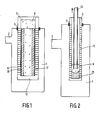
- FIG. 1 shows a device for producing a tubular green body 15.
- the membrane 11 is inserted, sealed by a seal 7, in a vessel 1 which can be evacuated via a pump nozzle 3.
- the pressure should preferably correspond to the partial pressure of the dispersing liquid in order to achieve the highest possible separation rate of solids.
- a fine-pored hose with preferably pores with a diameter ⁇ 40 nm can be inserted as the lining 17.
- Such a lining can be formed, for example, by a plastic tube as used for dialysis procedures. Hydrophilic plastics, for example surface-modified polyethylene, are preferred.
- the suspension is quickly sucked out of the device after reaching the desired layer thickness and replaced by a new, differently doped suspension.
- green bodies can be formed, which after sintering result in glasses with a refractive index gradient.
- a device is shown with which a rod-shaped green body 25 can be produced from the suspension 9 analogous to the method described in Figure 1 Tube 11 Introduced By deposition of SiO 2 particles in the entire tube cross section, a rod-shaped green body 25 grows.
- the filler tube 23 is pulled up synchronously with the growth of the green body 25. Because the suspension 9 is introduced into the tube 11 via the displaceable filler tube 23, there is the possibility of controlling the deposition process in such a way that the highest concentration of solid is always present in the suspension contained in the device in the lower region, so that a compact green body can grow.
- the suspension used, the deposition conditions as well as the post-processing of the green body obtained and the properties of the quartz glass body obtained correspond to the example described in FIG. 1, only the deposition time in this example was 120 min, since a solid rod was deposited.
- a e.g. tubular green body 15 can also be on the outside of a e.g. produce cylindrical membrane 21, which is porous in the separation area (see FIG. 3).
- the homogenized suspension 9 is poured into a vessel 19 and the membrane 21, which is immersed in the suspension 9, is evacuated from the inside via the pump nozzle 3.
- the suspension used, the deposition conditions as well as the finishing of the green body obtained and the properties of the quartz glass body obtained likewise correspond to the example described for FIG. 1 .
- a porous green body made from the starting material for the glass body can advantageously be used as the membrane, this green body also being able to be sintered on.
- filter tubes made of polyethylene with a pore diameter in the range from 10 to 20 ⁇ m can also be used as the membrane.
- plastic membranes with a porous lining a pore size ⁇ 4 0 nm in addition, in particular of a hydrophilic plastic fitted in the separation there is the advantage that the green bodies obtained a particularly smooth surface with a surface roughness of ⁇ 1 micron, preferably even ⁇ 0.5 um, have. Smooth surfaces of this type are therefore particularly advantageous because they can prevent disruptive recrystallization during the sintering of the green bodies.
Abstract
Verfahren und Vorrichtungen zur Herstellung von Glaskörpern, bei dem aus dem Ausgangsmaterial für den Glaskörper in Form einer Suspension mit hochdispersem Feststoffanteil ein poröser Grünkörper geformt und dieser anschließend gereinigt und gesintert wird, wobei der Grünkörper durch Trennung der Phasen der Suspension in einer Vorrichtung, in der sich eine Druckdifferenz aufbauen läßt, auf einer der Form des herzustellenden Glaskörpers entsprechenden porösen Membran mit Poren eines Durchmessers im Bereich zwischen dem 1-und 500-fachen des mittleren Teilchendurchmessers des Feststoffanteils der Suspension.
Description
Die Erfindung bezieht sich auf ein Verfahren zur Her stellung von Glaskörpem, bei dem aus dem Ausgangsmaterial für den Glaskörper in Form einer Suspension mit hochdispersem Feststoffanteil ein poröser Grünkörper geformt und dieser anschließend gereinigt und gesintert wird.The invention relates to a process for the manufacture of vitreous bodies, in which a porous green body is formed from the starting material for the vitreous body in the form of a suspension with a highly disperse solid component and this is then cleaned and sintered.
Die Erfindung bezieht sich weiter auf Vorrichtungen zur Durchführung eines solchen Verfahrens sowie auf die Verwendung der nach dem Verfahren gemäß der Erfindung hergestellten Glaskörper.The invention further relates to devices for carrying out such a method and to the use of the glass bodies produced by the method according to the invention.
Das eingangs genannte Verfahren ist insbesondere geeignet zur Herstellung von Vorformen für optische Wellenleiter.The method mentioned at the outset is particularly suitable for producing preforms for optical waveguides.
Zur Herstellung von hochreinen Quarzglaskörpem, insbesondere Vorformen für optische Wellenleiter, sind Verfahren bekannt, bei denen ein poröser Grünkörper aus hochdispersen SiO2-Glasteilchen hergestellt wird, wonach dieser poröse Grünkörper zunächst in z.B. einer chlorhaltigen Atmosphäre bei Temperaturen im Bereich von 600 bis 900°C gereinigt wird. Die Sinterung zu kompaktem, transparentem Glas erfolgt dann bei Temperaturen im Bereich um 1500°C; die Höhe der Sintertemperatur ist abhängig von der Größe der SiO2-Teichen und der Homogenität des Grünkörpers.For the production of high-purity quartz glass bodies, in particular preforms for optical waveguides, methods are known in which a porous green body is produced from highly disperse SiO 2 glass particles, after which this porous green body is initially in, for example, a chlorine-containing atmosphere at temperatures in the range from 600 to 900 ° C is cleaned. The sintering to compact, transparent glass then takes place at temperatures in the region of 1500 ° C; the level of the sintering temperature depends on the size of the SiO 2 ponds and the homogeneity of the green body.
Bei der Verarbeitung von hochdispersen Quarzgfaspartikeln ist ein erheblicher apparativer Aufwand (Vorformen für die Herstellung eines handhabbaren Grünkörpers und Pressen für die Verdichtung dieses Grünkörpers) erforderlich ist um schließlich einen Grünkörper zu erhalten, der die für eine effiziente Sinterung, d.h. Sinterung bei Temperaturen ≦ 1550°C zu einem blasen-und schlierenfreien Glaskörper, ausreichende hohe Dichte aufweist. Ein derartiges Verfahren zur Herstellung einer Vorform für optische Wellenleiter ist zB. aus DE-PS 32 40 355 bekanntWhen processing highly disperse quartz glass fiber particles, a considerable amount of equipment (preforms for the production of a manageable green body and presses for the compression of this green body) is required in order to finally obtain a green body which is suitable for efficient sintering, i.e. Sintering at temperatures ≦ 1550 ° C to a bubble-free and streak-free glass body, sufficiently high density. Such a method for producing a preform for optical waveguides is, for example. known from DE-PS 32 40 355
Um Grünkörper ausreichender Dichte herstellen zu können, ist es auch bekannt, von hochdispersen SiO2-Suspensionen auszugehen, die zu einem Grünkörper verformt werden. Aus DE-OS 29 25 309 ist ein Verfahren bekannt, bei dem eine Si02-Suspension in oder auf ein Trägerrohr aufgesprüht wird. Nachteilig bei diesem Verfähren ist, daß einmal hohe Anforderungen an eine gleichmäßig arbeitende Sprühvorrichtung gestellt werden müssen und daß eine Reinigung des erhaltenen Grünkörpers in einer mit den Verunreinigungen reagierenden heißen Gasatmosphäre nicht möglich ist da das Trägerrohr nicht porös istIn order to be able to produce green bodies of sufficient density, it is also known to start from highly disperse SiO 2 suspensions, which are deformed into a green body. From DE-OS 29 25 309 a method is known in which an Si0 2 suspension is sprayed into or onto a carrier tube. The disadvantage of this method is that high demands must be made of a uniformly operating spray device and that cleaning of the green body obtained in a hot gas atmosphere reacting with the impurities is not possible since the carrier tube is not porous
Der Erfindung liegt die Aufgabe zugrunde, ein Verfahren und Vorrichtungen zur Herstellung von hochreinen Glaskörpem zu schaffen, mit denen ein Grünkörper erhalten wird, der porös genug ist daß er in einem Zwischenerhitzungsschritt in einer mit vorliegenden Verunreinigungen reagierenden Gasatmosphäre gut gereinigt werden kann, der jedoch schon eine so hohe Verdichtung aufweist, daß-der anschließende Sinterschritt ohne zusätzliche Verdichtungsmaßnahmen des Grünkörpers erfolgen kann.The invention has for its object to provide a method and devices for the production of high-purity glass bodies, with which a green body is obtained which is porous enough that it can be cleaned well in an intermediate heating step in a gas atmosphere reacting with existing impurities, but it does has such a high compaction that the subsequent sintering step can take place without additional compaction measures of the green body.
Diese Aufgabe wird mit dem erfindungsgemäßen Verfahren dadurch gelöst daß der Grünkörper durch Trennung der Phasen der Suspension in einer Vorrichtung, in der sich eine Druckdifferenz aufbauen läßt auf einer der Form des herzustellenden Glaskörpers entsprechenden porösen Membran mit Poren eines Durchmessers im Bereich zwischen dem 1-und dem 500-fachen des mittleren Teilchendurchmessers des Feststoffanteils der Suspension abgeschieden wird. Vorrichtungen zur Durchführung dieses Verfahrens sind gekennzeichnet durch
- 1. ein über einen Pumpstutzen evakuierbares Gefäß, in welchem eine der Form des herzustellenden Glaskörpers entsprechende poröse Membran mit Poren eines Durchmessers im Bereich zwischen dem 1-und dem 500-fachen des mittleren Teilchendurchmessers des Feststoffanteils einer in der Vorrichtung nach Phasen zu trennenden Suspension, vorzugsweise ≦ 20 µm, im Abscheidebereich und mit einem nichtporösen, außerhalb des evakuierbaren Bereiches liegenden, gegen den zu evakuierenden Bereich des Gefäßes durch eine Dichtung abgedichteten Einfüllstutzen, über den nach Phasen zu trennendes Ausgangsmaterial in Form einer Suspension einfüllbar ist, oder
- 2. ein Gefäß, in das nach Phasen zu trennendes Ausgangsmaterial in Form einer Suspension einfüllbar ist mit einer in die Suspension eintauchenden, der Form des herzustellenden Grünkörpers entsprechenden, über einen Pumpstutzen evakuierbaren porösen Membran mit Poren eines Durchmessers im Bereich zwischen dem 1-und dem 500-fachen des mittleren Teilchendurghmessers des Feststoffanteils einer in der Vorrichtung nach Phasen zu trennenden Suspension, vorzugsweise ≦ 20 µm, im Abscheidebereich.
- 1. a vessel which can be evacuated via a pump nozzle, in which a porous membrane corresponding to the shape of the glass body to be produced and having pores with a diameter in the range between 1 and 500 times the average particle diameter of the solids content of a suspension to be separated in the device according to phases, preferably ≦ 20 µm, in the separation area and with a non-porous, outside the evacuable area, sealed against the area of the vessel to be evacuated by a filler neck, via which starting material to be separated in phases can be filled in the form of a suspension, or
- 2. A vessel into which the starting material to be separated according to phases can be filled in the form of a suspension with a porous membrane with pores with a diameter in the range between 1 and 2 which can be evacuated via a pump connector and is immersed in the suspension and corresponds to the shape of the green body to be produced 500 times the average particle diameter of the solids content of a suspension to be separated in the device according to phases, preferably ≦ 20 µm, in the separation area.
Nach vorteilhaften Weiterbildungen des Verfahrens nach der Erfindung wird ein Unterdruck oder ein Überdruck in der Vorrichtung erzeugt Hiermit ist der Vorteil verbunden, daß eine relativ hohe Abscheiderate des Feststoffanteils der Suspension erreicht wird.According to advantageous developments of the method according to the invention, a negative pressure or an excess pressure is generated in the device. This has the advantage that a relatively high separation rate of the solids content of the suspension is achieved.
Nach vorteilhaften Weiterbildungen des Verfahrens gemäß der Erfindung wird als Ausgangsmaterial für den Glaskörper eine Suspension eingesetzt, die SiO2-Partikel eines Durchmessers im Bereich von 10 bis 500 nm, vorzugsweise 15 bis 100 nm, mit einem mittleren Teilchendurchmesser von 40 nm bei einem Festsfoff:Wasser-Gewichtsverhättnis von 1:1 bis 1:2 enthält Hiermit ist der Vorteil verbunden, daß Grünkörper erreicht werden können mit einer vorteilhaft hohen Dichte, wie sie für den späteren Sinterprozeß des Grünkörpers erforderlich istAccording to advantageous developments of the method according to the invention, a suspension is used as the starting material for the vitreous body, the SiO 2 particles having a diameter in the range from 10 to 500 nm, preferably 15 to 100 nm, with an average particle diameter of 40 nm with a solid: Water to weight ratio of 1: 1 to 1: 2 contains the advantage that green bodies can be obtained with an advantageously high density, as is required for the later sintering process of the green body
Nach einer weiteren vorteilhaften Ausgestaltung des Verfahrens nach der Erfindung wird der Suspension ein ionogener Zusatzstoff zugegeben, der den pH-Wert der Suspension in den basischen Bereich (pH ≦ 10) verschiebt, vorzugsweise wird hierzu eine Ammoniumverbindung in einer Menge von 0,1 bis 5 Gew. %, bezogen auf den Feststoffanteil der Suspension, eingesetzt Dieser Zusatzstoff ist leicht flüchtig und ist in einem nachfolgenden Reinigungs-Erhitzungsschritt rückstandslos aus dem Grünkörper zu entfemen, so daß Quarzglaskörper einer sehr hohen Reinheit herstellbar sind. Durch den Zusatz einer Ammoniumverbindung, beispielsweise NH3 in wässeriger Lösung, werden Grünkörper einer relativ hohen Festigkeit erreicht, da sie vemetzungsfördemd wirkt, wobei an den Kontaktstellen zweier SiO2-Primärpartikel eine Gelbildung auftritt Bei beispielsweise einer Suspensionstemperatur von 20°C und einem pH-Wert ≦ 10 geht Si02 in der Größenordnung von etwa 100 ppm in Lösung und wird an den Kontaktstellen ausgeschieden und bildet damit eine Brückenschicht Wird als ionogener Zusatzstoff z.B. NH4F in wässeriger Lösung eingesetzt kann eine Fluordotierung des Ausgangsmaterials zur Verringerung des Brechungsindex erreicht werden. Derartige Gläser sind als Mantelgläser für optische Wellenleiter geeignet.According to a further advantageous embodiment of the method according to the invention, an ionogenic additive is added to the suspension, which shifts the pH of the suspension into the basic range (pH ≦ 10), preferably an ammonium compound in an amount of 0.1 to 5 % By weight, based on the solids content of the suspension, is used. This additive is volatile and can be removed without residue from the green body in a subsequent cleaning and heating step, so that quartz glass bodies of very high purity can be produced. By adding an ammonium compound, for example NH 3 in aqueous solution, green bodies of relatively high strength are achieved since they have a cross-linking effect, with gel formation occurring at the contact points of two SiO 2 primary particles, for example at a suspension temperature of 20 ° C. and a pH Value ≦ 10 Si0 2 is of the order of about 100 ppm in solution and is excreted at the contact points and thus forms a bridge layer. If an ionogenic additive such as NH 4 F is used in aqueous solution, fluorine doping of the starting material can be achieved to reduce the refractive index. Such glasses are suitable as cladding glasses for optical waveguides.
Nach einer vorteilhaften Weiterbildung des Verfahrens nach der Erfindung wird auf der Membran ein Schichtkörper durch Abscheiden mehrerer Schichten nacheinander aus unterschiedlich dotierten Suspensionen abgeschieden. Dazu wird nach Erreichen einer gewünschten Schichtdicke des Grünkörpers die erste Suspension aus der Vorrichtung entfernt und der Abscheideprozeß mit einer zweiten, z.B. anders als die erste Suspension dotierten Suspension fortgesetzt Das vorliegende Verfahren ist damit besonders geeignet, Vorformen für optische Wellenleiter herzustellen, die ein Stufenprofil des Brechungsindex aufweisen. Ebenfalls ist es möglich, einen optischen Wellenleiter mit W-Profil durch Einbau einer Zwischenschicht mit niedrigerem Brechungsindex, die durch Anwendung einer Suspension mit entsprechender Dotierung erhalten wird, herzustellen. Dotierstoffe zur Veränderung des Brechungsindex eines Glaskörpers sind dem Fachmann bekannt, beispielsweise werden hierzu zur Erhöhung des Brechungsindex Ge02 oder Al2O3, und zur Erniedrigung des Brechungsindex B203 oder Fluor verwendet Mit dem vorliegenden Verfahren ist es auch möglich, durch Abscheidung einer Vielzahl von abgestuft dotierten Schichten einen Quarzglaskörper mit angenähert kontinuierlichem Brechungsindexverlauf herzustellen. Nach einer weiteren vorteilhaften Ausgestaltung des Verfahrens nach der Erfindung wird als Membran ein poröser Grünkörper aus dem Ausgangsmaterial für den herzustellenden Glaskörper eingesetzt Hiermit ist der Vorteil verbunden, daß für die Herstellung von Vorformen für optische Wellenleiter nach dem erfindungsgemäßen Verfahren' artfremde Materialien für die Membran vermieden werden können, die eventuell zu Verunreinigungen des erhaltenen Grünkörpers führen können, wobei auch auf diese Weise hochpräzise optische Wellenleiter geschaffen werden können mit einem Stufenprofil des Brechungsindex. Bei dieser Abwandlung des erfindungsgemäßen Verfahrens werden Membran und abgeschiedener Grünkörper gemeinsam in einem Reinigungsschritt in einer geeigneten erhitzten Gasatmosphäre gereinigt und anschließend gemeinsam zu einem transparenten Glaskörper gesintert Statt eines porösen, noch nicht gesinterten Körpers aus dem Ausgangsmaterial für den Glaskörper (Grünkörper) kann auch ein poröser, angesinterter Körper aus dem Ausgangsmaterial für den Glaskörper als Membran eingesetzt werden. Hierbei ist besonders vorteilhaft, daß Schichten aus dem Feststoffanteil der Suspension mit einer gegenüber der für die Herstellung einer solchen Membran verwendeten Komfraktion geänderten Komfraktion hergestellt werden können. Von der Komfraktion ist das Schwindungsverhalten eines Körpers abhängig; wenn als Membran ein bereits angesinterter Körper aus dem Ausgangsmaterial für Glaskörper verwendet wird, ist es möglich, die Membran und die auf ihr abzuscheidende Schicht in ihren Schwindungsverhalten einander anzupassen.According to an advantageous development of the method according to the invention, a layered body is deposited on the membrane by depositing several layers in succession from differently doped suspensions. To after a desired layer thickness of the green body has been reached, the first suspension is removed from the device and the deposition process is continued with a second suspension, for example doped differently from the first suspension. The present method is therefore particularly suitable for producing preforms for optical waveguides which have a step profile of the refractive index exhibit. It is also possible to produce an optical waveguide with a W profile by incorporating an intermediate layer with a lower refractive index, which is obtained by using a suspension with appropriate doping. Dopants for changing the refractive index of a vitreous body are known to the person skilled in the art, for example Ge0 2 or Al 2 O 3 is used for increasing the refractive index and for lowering the refractive index B20 3 or fluorine. With the present method it is also possible to deposit a large number of substances to produce a quartz glass body with graded doped layers with an approximately continuous refractive index curve. According to a further advantageous embodiment of the method according to the invention, a porous green body made of the starting material for the glass body to be produced is used as the membrane. This has the advantage that for the manufacture of preforms for optical waveguides according to the method of the invention, 'non-native materials for the membrane are avoided that can possibly lead to contamination of the green body obtained, it also being possible in this way to create high-precision optical waveguides with a step profile of the refractive index. In this modification of the method according to the invention, the membrane and the deposited green body are cleaned together in a cleaning step in a suitable heated gas atmosphere and then sintered together to form a transparent glass body. Instead of a porous, not yet sintered body made from the starting material for the glass body (green body), a porous one can also be used , sintered body from the starting material for the vitreous body can be used as a membrane. It is particularly advantageous here that layers can be produced from the solids content of the suspension with a comfraction which is different from the comfraction used for the production of such a membrane. The shrinkage behavior of a body depends on the comfraction; if an already sintered body made of the starting material for vitreous bodies is used as the membrane, it is possible to adapt the shrinkage behavior of the membrane and the layer to be deposited thereon.
Wird der Grünkörper nach einer vorteilhaften Weiterbildung des Verfahrens nach der Erfindung auf einer Membran abgeschieden, deren Abscheideoberfläche mit einem Futter insbesondere aus Kunststoff ausgekleidet ist, das eine Porosität dem mittleren Teilchendurchmessers des Feststoffanteils der Suspension aufweist, wobei insbesondere eine Kunststoffmembran aus vorzugsweise Polyäthylen eines Porendurchmessers im Bereich von 10 bis 20 um eingesetzt wird, ergibt sich der Vorteil, daß eine Entfernung auch größerer Grünkörper problemlos vorgenommen werden kann. Für das Futter wird vorzugsweise ein hydrophiler Kunststoff eingesetztIf, according to an advantageous development of the method according to the invention, the green body is deposited on a membrane, the separating surface of which is lined with a lining, in particular made of plastic, which has a porosity of the average particle diameter of the solids content of the suspension, in particular a plastic membrane preferably made of polyethylene with a pore diameter in the Is used in the range of 10 to 20 microns, there is the advantage that even larger green bodies can be easily removed. A hydrophilic plastic is preferably used for the feed
Bei größeren Abmessungen des Grünkörpers kann es vorteilhaft sein, statt einer einteiligen eine teilbare, mehrteilige Membran einzusetzen.With larger dimensions of the green body, it can be advantageous to use a divisible, multi-part membrane instead of a one-part one.
Die mit der Erfindung erzielbaren Vorteile bestehen weiter insbesondere darin, daß für die Herstellung von Glaskörpern, insbesondere Vorformen für optische Wellenleiter, mit einem sehr geringen apparativen Aufwand Grünkörper erhalten werden können, die einerseits porös genug sind, daß Verunreinigungen in einer erhitzten Gasatmosphäre wirkungsvoll entfernt werden können, die andererseits jedoch eine so hohe Dichte und" Homogenität aufweisen, daß sie ohne weitere Zwischenbearbeitungsschritte, wie z.B. isostatisches Heißpressen, zu hochreinen Glaskörpern gesintert werden können. Ein weiterer großer Vorteil des Verfahrens der vorliegenden Erfindung ist, daß Grünkörper hergestellt werden können, die einen von einem kreisförmigen Querschnitt abweichenden Querschnitt aufweisen; zu denken ist z.B. an eckige Rohre oder Stäbe oder auch an beliebig geformte Hohlkörper. Die abgeschiedenen Grünkörper lassen sich rißfrei trocknen und ergeben nach dem Reinigungs-und Sinterschnitt maßtreue, transparente und hochreine Gläser mit hochglatten Oberflächen. Weiter ist es auch möglich, auf die beschriebene Weise hergestellte Quarzglasrohre bei der Herstellung von Halogen-oder Gasentladungslampen einzusetzen, wo ebenfalls, wie auch für Grünkörper, die für die Herstellung von optischen Wellenleitern verwendet werden sollen, ein sehr niedriger Wassergehalt und ein hoher Siliciumdioxidgehalt gefordert istThe advantages that can be achieved with the invention further consist, in particular, in that, for the manufacture of glass bodies, in particular preforms for optical waveguides, green bodies can be obtained with very little outlay on equipment, which on the one hand are porous enough that impurities are effectively removed in a heated gas atmosphere which, on the other hand, have such a high density and "homogeneity that they can be sintered into high-purity glass bodies without further intermediate processing steps, such as hot isostatic pressing. Another great advantage of the process of the present invention is that green bodies can be produced which have a cross-section deviating from a circular cross-section, for example angular pipes or rods or also hollow bodies of any shape.The separated green bodies can be dried without cracks and result in transparent, true-to-size after the cleaning and sintering cut te and high-purity glasses with smooth surfaces. Furthermore, it is also possible to use quartz glass tubes produced in the manner described in the production of halogen or gas discharge lamps, where likewise, as for green bodies which are to be used for the production of optical waveguides, a very low water content and a high silicon dioxide content are required is
Durch das Abtrennen der Dispergierflüssigkeft von der festen Phase der Suspension über die Druckdifferenz in der Vorrichtung bildet sich ein relativ trockener, fester Grünkörper, einer Dichte im Bereich von 38-50% der Dichte kompaktem Glases, der gut handhabbar ist und der, ohne daß die Gefahr einer Rißbildung auftritt, in relativ kurzer Zeit von der geringen verbliebenen Restfeuchte befreit werden kann, z.B. durch Trocknen unter atmosphärischen Bedingungen oder durch Lösungsmittelaustausch. Diese Trockenprozesse sind dem einschlägig tätigen Fachmann vertrautBy separating the dispersing liquid from the solid phase of the suspension via the pressure difference in the device, a relatively dry, solid green body is formed, a density in the range of 38-50% of the density of compact glass, which is easy to handle and which without the Risk of cracking occurs, can be freed from the low residual moisture in a relatively short time, for example by drying under atmospheric conditions or by solvent exchange. These drying processes are familiar to the relevant specialist
Wird eine Membran mit einer Porengröße von 10 bis 20 um zur Abscheidung des Feststoffes aus der Suspension, der einen mittleren Teilchendurchmesser von 40 nm hat, eingesetzt, bildet die zu Beginn des Abscheideprozesses auf der Membran abgeschiedene Schicht eine zusätzliche Feinfilterschicht, die ein weiteres Eindringen von Feststoffpartikeln aus der Suspension in die Membran verhindert.If a membrane with a pore size of 10 to 20 µm is used to separate the solid from the suspension, which has an average particle diameter of 40 nm, the layer deposited on the membrane at the beginning of the separation process forms an additional fine filter layer which prevents further penetration of Prevents solid particles from the suspension in the membrane.
Dieser Effekt einer zusätzlichen Feinfilterschicht kann auch erreicht werden, wenn die Membran an ihrer Abscheideoberfläche mit einem Futter ausgekleidet wird, das eine Porosität mit einer Porengröße 5 dem mittleren Teilchendurchmesser des Feststoffanteils der Suspension aufweist Ein solches Futter wird zweckmäßigerweise aus einem hydrophilen Kunststoff hergestelltThis effect of an additional fine filter layer can also be achieved if the membrane is lined on its separating surface with a lining which has a porosity with a pore size of 5 the average particle diameter of the solids content of the suspension. Such a lining is expediently made from a hydrophilic plastic
Ausführungsbeispiele der Erfindung sind in der Zeichnung dargestellt und werden im folgenden näher beschrieben. Es zeigen:
- Fig. 1 Vorrichtung zur Durchführung des Verfahrens nach der Erfindung im Schnitt zur Herstellung von rohrförmigen Grünkörpem,
- Fig. 2 Abwandlung der Vorrichtung gemäß Figur 1 im Schnitt zur Herstellung von stabförmigen Grünkörpem,
- Fig. 3 Eine weitere Vorrichtung zur Durchführung des Verfahrens nach der Erfindung im Schnitt.
- 1 device for performing the method according to the invention in section for the production of tubular green bodies,
- 2 modification of the device according to FIG. 1 in section for the production of rod-shaped green bodies,
- Fig. 3 Another device for performing the method according to the invention in section.
In Figur 1 ist eine Vorrichtung zur Herstellung eines rohrförmigen Grünkörpers 15 dargestellt Dazu wird eine, z.B. in einem Ultraschallfeld homogenisierte, vorzugsweise wässerige Suspension aus hochdispersen SiO; Teilchen eines Teilchendurchmessers im Bereich von 10 bis 500 nm, vorzugsweise 15 bis 100 nm, mit einem mittleren Teilchendurchmesser von 40 nm, mit Wasser als Dispergierflüssigkeit (Fesrstoff-Wasser-Gewichtsverhältnis 1:1 bis 1:2), der NG3, in wässeriger Lösung in einer Menge von 0,1 bis 5 Gew. %, bezogen auf den Feststoffanteil der Suspension zugesetzt ist, in eine rohrförmige Membran 11 eines Innendurchmessers von 24 mm, die im Abscheidungsbereich des Grünkörpers 15 Poren einer Porengröße ≦ 20 um aufweist, eingefullt Die Membran 11 steckt, abgedichtet über eine Dichtung 7, in einem Gefäß 1, das über einen Pumpstutzen 3 evakuierbar ist Der Druck sollte vorzugsweise dem Partialdruck der Dispergierflüssigkeit entsprechen, um eine möglichst hohe Abscheiderate an Feststoff zu erreichen. Zur einfacheren Entformung des erhaltenen Grünkörpers 15 kann ein feinstporiger Schlauch mit vorzugsweise Poren eines Durchmessers ≤ 40 nm als Futter 17 eingelegt sein. Ein solches Futter kann z.B. durch einen Kunststotffschlauch gebildet werden, wie er für Dialyseverfahren eingesetzt wird. Zu bevorzugen sind hydrophile Kunststoffe, beispielsweise oberflächenmodifiziertes Polyäthylen.FIG. 1 shows a device for producing a tubular
In einem praktischen Ausführungsbeispiel unter Anwendung einer Vorrichtung nach Figur 1 wurde wie folgt verfahren: 200 g von im Handel erhältlichem Si02 einer Teilchengröße von 15-100 nm mit einem mittleren Teilchendurchmesser von 40 nm werden in 300 ml Wasser und 7 ml wässeriger 25%iger Ammoniaklösung dispergiert, bis eine homogene Suspension erreicht wird. Eine Homogenisierung kann z.B. durch Einkoppeln eines Ultraschallfeldes mit einer Frequenz f=35 kHz in die Suspension erreicht werden. Diese Suspension wird wie zu Figur 1 beschrieben nach Phasen getrennt durch Erzeugen eines Unterdrucks von 15 mbar. Der nach einer Abscheidungsdauer von 15 min erhaltene Grünkörper wird zur Entfernung der Restfeuchte in der Vorrichtung langsam getrocknetIn a practical exemplary embodiment using a device according to FIG. 1, the procedure was as follows: 200 g of commercially available SiO 2 with a particle size of 15-100 nm and an average particle diameter of 40 nm are dissolved in 300 ml of water and 7 ml of aqueous 25% strength Dispersed ammonia solution until a homogeneous suspension is achieved. Homogenization can be achieved, for example, by coupling an ultrasonic field with a frequency f = 35 kHz into the suspension. As described for FIG. 1, this suspension is separated into phases by generating a negative pressure of 15 mbar. The green body obtained after a deposition time of 15 min is slowly dried in the device to remove the residual moisture
Der auf diese Weise erhaltene Grünkörper weist eine Dichte von 42% der Dichte kompakten Quarzglases auf. Anschließend wird der Grünkörper in 100 min auf eine Temperatur von 800°C erhitzt und zur Entfernung von Verunreinigungen, insbesondere Wasser und Übergangsmetalle, 1.5, h einem mit SOCl2 gesättigten O2-Gasstrom ausgesetzt Die an schließende Sinterung erfolgt bei 1500°C in Heliumatmosphäre mit 2 Vol% Chlorgaszusatz, wobei der Grünkörper mit einer Absenkge- schwindigkeit von 3mmfmin durch den Ofen geführt wird. Es wird ein transparentes Glasrohr eines Außendurchmessers von 18 mm und einer Wandstärke von 3 mm mit Verunreinigungen < 10 ppb erhalten. Das auf diese Weise hergestellte Glas hatte eine Dichte von 2,20 g/cm3 und einen Brechungsindex nD= 1,4598.The green body obtained in this way has a density of 42% of the density of compact quartz glass. Then, the green body 100 is heated min to a temperature of 800 ° C and to remove impurities, especially water, and transition metals, 1 .5 h a saturated SOCl 2 O 2 gas flow subjected to takes place at closing sintering at 1500 ° C in a helium atmosphere with 2% by volume chlorine gas addition, wherein the green body having a Absenkge- schwindigke i t is run by 3mmfmin through the furnace. A transparent glass tube with an outer diameter of 18 mm and a wall thickness of 3 mm with impurities <10 ppb is obtained. The glass produced in this way had a density of 2.20 g / cm 3 and a refractive index n D = 1.4598.
Nach dem beschriebenen Verfahren ist es ebenfalls möglich, Schichtstrukturen aus unterschiedlich dotierten SiO2-Suspensionen zu erzeugen. Dazu wird die Suspension nach Erreichen der gewünschten Schichtdicke schnell aus der Vorrichtung abgesaugt und durch eine neue, anders dotierte Suspension ersetzt. Auf diese Weise lassen sich Grünkörper formen, die nach dem Sintern Gläser mit einem Brechungsindexgradienten ergeben.According to the method described, it is also possible to produce layer structures from differently doped SiO 2 suspensions. For this purpose, the suspension is quickly sucked out of the device after reaching the desired layer thickness and replaced by a new, differently doped suspension. In this way, green bodies can be formed, which after sintering result in glasses with a refractive index gradient.
In Figur 2 ist eine Vorrichtung dargestellt, mit der sich analog zu dem gemäß Figur 1 beschriebenen Verfahren ein stabförmiger Grünkörper 25 aus der Suspension 9 herstellen läßt Über ein in Achsrichtung der Membran in Form des Rohres 11 verschiebbares Einfüllrohr 23 wird die homogenisierte Suspension 9 in das Rohr 11 eingeleitet Durch Abscheidung von SiO2-Partikeln im gesamten Rohrquerschnitt wächst ein stabförmiger Grünkörper 25 an. Das Einfüllrohr 23 wird synchron mit dem Wachstum des Grünkörpers 25 hoch gezogen. Dadurch, daß die Suspension 9 über das verschiebbare Einfüllrohr 23 in das Rohr 11 eingeleitet wird, ergibt sich die Möglichkeit, den- Abscheidungsprozeß so zu steuern, daß im unteren Bereich stets die höchste Konzentration an Feststoff innerhalb der in der Vorrichtung enthaltenen Suspension vorliegt, so daß ein kompakter Grünkörper anwachsen kann.In Figure 2, a device is shown with which a rod-shaped
Die angewendete Suspension, die Abscheidebedingungen wie auch die Nachbearbeitung des erhaltenen Grünkörpers sowie die Eigenschaften des erhaltenen Quarzglaskörpers entsprechen dem zu Figur 1 beschriebenen Beispiel, nur die Abscheidedauer betrug bei diesem Beispiel 120 min, da ein massiver Stab abgeschieden wurde.The suspension used, the deposition conditions as well as the post-processing of the green body obtained and the properties of the quartz glass body obtained correspond to the example described in FIG. 1, only the deposition time in this example was 120 min, since a solid rod was deposited.
Ein z.B. rohrförmiger Grünkörper 15 läßt sich auch auf der Außenseite einer z.B. zylinderförmigen Membran 21, die im Abscheidebereich porös ist, herstellen (vergleiche Figur 3). Hierzu wird die homogenisierte Suspension 9 in ein Gefäß 19 eingefüllt und die Membran 21, die in die Suspension 9 eintaucht, wird über den Pumpstutzen 3 von innen evakuiert.A e.g. tubular
Die angewendete Suspension, die Abscheidebedingungen wie auch die Nachbearbeitung des erhaltenen Grünkörpers sowie die Eigenschaften des erhaltenen Quarzglaskörpers entsprechen ebenfalls dem zu Figur 1 beschriebenen Beispiel.The suspension used, the deposition conditions as well as the finishing of the green body obtained and the properties of the quartz glass body obtained likewise correspond to the example described for FIG. 1 .
Als Membran kann mit Vorteil ein poröser Grünkörper aus dem Ausgangsmaterial für den Glaskörper eingesetzt werden, wobei dieser Grünkörper auch bereits angesintert sein kann. Als Membran können jedoch auch z.B. Filterrohre aus Polyäthylen mit einem Porendurchmesser im Bereich von 10 bis 20 µm verwendet werden. Wenn solche Kunststoffmembranen zusätzlich mit einem porösen Futter einer Porengröße ≦ 40 nm, insbesondere aus einem hydrophilen Kunststoff im Abscheidebereich ausgestattet werden, ergibt sich der Vorteil, daß die erhaltenen Grünkörper eine besonders glatte Oberfläche mit einer Oberflächenrauhigkeit <1µm, vorzugsweise sogar < 0,5 um, aufweisen. Derartige glatte Oberflächen sind deswegen besonders vorteilhaft, weif damit eine störende Rekristallisation bei der Sinterung der Grünkörper vermieden werden kann.A porous green body made from the starting material for the glass body can advantageously be used as the membrane, this green body also being able to be sintered on. However, filter tubes made of polyethylene with a pore diameter in the range from 10 to 20 μm can also be used as the membrane. When such plastic membranes with a porous lining a pore size ≦ 4 0 nm in addition, in particular of a hydrophilic plastic fitted in the separation, there is the advantage that the green bodies obtained a particularly smooth surface with a surface roughness of <1 micron, preferably even <0.5 um, have. Smooth surfaces of this type are therefore particularly advantageous because they can prevent disruptive recrystallization during the sintering of the green bodies.
Claims (24)
daß der Grünkörper durch Trennung der Phasen der Suspension in einer Vorrichtung, in der sich eine Druckdifferenz aufbauen läßt, auf einer der Form des herzustellenden Glaskörpers entsprechenden porösen Membran mit Poren eines Durchmessers im Bereich zwischen dem 1-und 500- fachen des mittleren Teilchendurchmessers des Feststoffanteils der Suspension abgeschieden wird. 1st Process for the production of vitreous bodies, in which a porous green body is formed from the starting material for the vitreous body in the form of a suspension with a highly disperse solid component and this is subsequently cleaned and sintered, thereby characterized
that the green body by separating the phases of the suspension in a device in which a pressure difference can be built up on a porous membrane corresponding to the shape of the glass body to be produced, with pores with a diameter in the range between 1 and 500 times the average particle diameter of the solids content the suspension is deposited.
dadurch aekennzeichnet
daß als Ausgangsmaterial für den Glaskörper eine wässerige Suspension eingesetzt wird, die SiO2-Partikel eines Durchmessers im Bereich von 10 bis 500 nm, vorzugsweise 15 bis 100 nm, mit einem mittleren Teilchendurchmessers von 40 nm enthält4. The method according to any one of claims 1 to 3,
thereby marked
that an aqueous suspension is used as a starting material for the glass body, the SiO having a diameter in the range from 10 nm 2 particles to 500, preferably 15 to 1 00 nm, having an average particle diameter of 40 nm containing
dadurch aekennzeichnet
daß eine Suspension mit einem Feststoff:Wasser-Gewichtsverhältnis von 1:1 bis 1:2 eingesetzt wird.5. The method according to any one of claims 1 to 4,
thereby marked
that a suspension with a solid: water weight ratio of 1: 1 to 1: 2 is used.
dadurch aekennzeichnet
daß der Suspension ein ionogener Zusatzstoff zugegeben wird, der den pH-Wert der Suspension in den basischen Bereich (pH≦ 10) verschiebt6. The method according to claims 4 and 5,
thereby marked
that an ionogenic additive is added to the suspension, which shifts the pH of the suspension into the basic range (pH ≦ 10)
daß als ionogener Zusatzstoff eine Ammoniumverbindung zugesetzt wird.7. The method according to claim 6, characterized
that an ammonium compound is added as an ionogenic additive.
dadurch aekennzeiahnet
daß der ionogene Zusatzstoff in einer Menge von 0,1 bis 5 Gew.%, bezogen auf den Feststoffanteil der Suspension, zugegeben wird.8. The method according to claim 6 or 7,
thereby aekennzeiahnet
that the ionogenic additive is added in an amount of 0.1 to 5% by weight, based on the solids content of the suspension.
dadurch gekennzeichnet
daß auf der Membran ein Schichtkörper durch Abscheiden mehrerer Schichten nacheinander aus unterschiedlich dotierten Suspensionen abgeschieden wird.9. The method according to any one of claims 1 to 8,
characterized
that a laminate is deposited on the membrane by depositing several layers in succession from differently doped suspensions.
daß Suspensionen mit Dotierstoffen eingesetzt werden, die unterschiedliche Brechungsindices des herzustellenden Glaskörpers bewirken.10. The method according to claim 9, characterized.
that suspensions with dopants are used which cause different refractive indices of the glass body to be produced.
daß als Membran ein poröser Grünkörper aus dem Ausgangsmaterial für den herzustellenden Glaskörper eingesetzt wird.11. The method according to claim 1, characterized
that a porous green body made of the starting material for the glass body to be produced is used as the membrane.
daß der Grünkörper auf einer Membran abgeschieden wird, deren Abscheideoberfläche mit einem Futter, insbesondere aus Kunststoff, ausgekleidet ist, das eine Porosität kleiner als oder gleich dem mittleren Teilchendurchmesser des Feststoffanteils der Suspension aufweist12. The method according to claim 1, characterized
that the green body is deposited on a membrane, the separation surface of which is lined with a lining, in particular made of plastic, which has a porosity less than or equal to the average particle diameter of the solids content of the suspension
daß eine Kunststoffmembran, vorzugsweise aus Polyäthylen, eingesetzt wird.13. The method according to claim 1 , characterized.
that a plastic membrane, preferably made of polyethylene, is used.
dadurch aekennzeichnet
daß eine Membran mit Poren eines Durchmessers ≦ 20µm eingesetzt wird.14. The method according to any one of claims 1 to 13,
thereby marked
that a membrane with pores with a diameter of µ 20µm is used.
dadurch aekennzeichnet.
daß in der Vorrichtung ein Unterdruck bis 15 mbar oder ein Überdruck bis 10 bar erzeugt wird.15. The method according to any one of claims 1 to 14,
thereby marked.
that a negative pressure of up to 15 mbar or an excess pressure of up to 10 bar is generated in the device.
ein über einen Pumpstutzen (3) evakuierbares Gefäß (1), in welchem eine der Form des herzustellenden Glaskörpers entsprechende poröse Membran mit Poren eines Durchmessers im Bereich zwischen dem 1-und 500-fachen des mittleren Teilchendurchmessers des Feststoffanteils einer in der Vorrichtung nach Phasen zu trennenden Suspension, vorzugsweise ≦ 20 um, im Abscheidebereich und mit einem nichtporösen, außerhalb des evakuierbaren Bereiches liegenden, gegen den zu evakuierenden Bereich des Gefäßes durch eine Dichtung (7) abgedichteten Einfüllstutzen (5), über den nach Phasen zu trennendes Ausgangsmaterial in Form einer Suspension (9) einfüllbar ist16. Device for performing the method according to claims 1 to 15 characterized by
a vessel (1) which can be evacuated via a pump connection piece (3) and in which a porous membrane corresponding to the shape of the glass body to be produced and having pores with a diameter in the range between 1 and 500 times the average particle diameter of the solids content in one according to phases separating suspension, preferably ≦ 20 µm, in the separation area and with a non-porous filler neck (5), which is outside the evacuable area and sealed against the area to be evacuated by a seal (7), via the starting material to be separated in phases in the form of a Suspension (9) can be filled
daß die Membran ein Zylinder (11) mit einem nichtporösen Boden (13) ist, in welchem ein rohrförmiger Grünkörper - (15) abscheidbar ist17. The apparatus according to claim 16, characterized.
that the membrane is a cylinder (11) with a non-porous base (13) in which a tubular green body - (15) can be separated
daß die Membran an ihrer Abscheidefläche mit einem Futter, insbesondere aus einem hydrophilen Kunststoff, (17) ausgekleidet ist, das eine Porosität kleiner als oder gleich dem mittleren Teilchendurchmesser des Feststoffes der Suspension aufweist18. The apparatus according to claim 16, characterized.
that the membrane on its separation surface is lined with a lining, in particular made of a hydrophilic plastic (17), which has a porosity less than or equal to the average particle diameter of the solid of the suspension
dadurch aekennzeichnet.
daß innerhalb der Membran in Form des Zylinders (11) ein in Achsrichtung des Zylinders (11) verschiebbares Einfüllrohr (23) vorgesehen ist, über welches die Suspension (9) zur Abscheidung eines stabförmigen Grünkörpers - (25) in die Membran einfüllbar ist19. Device according to one of claims 16 to 18,
thereby marked.
that inside the membrane in the form of the cylinder (11) there is a filler tube (23) which can be displaced in the axial direction of the cylinder (11) and via which the suspension (9) for separating a rod-shaped green body (25) can be filled into the membrane
daß die Membran ein Zylinder (21) is, auf welchem ein rohrförmiger Grünkörper (15) abscheidbar ist21. The apparatus according to claim 20, characterized
that the membrane is a cylinder (21) on which a tubular green body (15) can be deposited
dadurch gekennzeichnet,
daß die Membran ein poröser Grünkörper aus dem Ausgangsmaierial für den herzustellenden Glaskörper ist22. The device according to one of claims 1 6 to 2 1 ,
characterized,
that the membrane is a porous green body from the starting material for the glass body to be produced
Applications Claiming Priority (2)
| Application Number | Priority Date | Filing Date | Title |
|---|---|---|---|
| DE19853511457 DE3511457A1 (en) | 1985-03-29 | 1985-03-29 | METHOD AND DEVICES FOR THE PRODUCTION OF GLASS BODIES |
| DE3511457 | 1985-03-29 |
Publications (2)
| Publication Number | Publication Date |
|---|---|
| EP0196717A1 true EP0196717A1 (en) | 1986-10-08 |
| EP0196717B1 EP0196717B1 (en) | 1989-03-15 |
Family
ID=6266700
Family Applications (1)
| Application Number | Title | Priority Date | Filing Date |
|---|---|---|---|
| EP86200483A Expired EP0196717B1 (en) | 1985-03-29 | 1986-03-21 | Method and apparatus for making glass bodies |
Country Status (5)
| Country | Link |
|---|---|
| US (1) | US4684387A (en) |
| EP (1) | EP0196717B1 (en) |
| JP (1) | JPH0788227B2 (en) |
| CA (1) | CA1277819C (en) |
| DE (2) | DE3511457A1 (en) |
Cited By (1)
| Publication number | Priority date | Publication date | Assignee | Title |
|---|---|---|---|---|
| DE102006010808B4 (en) * | 2006-03-07 | 2009-08-13 | BEGO Bremer Goldschlägerei Wilh. Herbst GmbH & Co. KG | Apparatus, system, method, computer program and data carrier for electrophoretic deposition with a movable electrode |
Families Citing this family (11)
| Publication number | Priority date | Publication date | Assignee | Title |
|---|---|---|---|---|
| JPH0225025A (en) * | 1988-07-14 | 1990-01-26 | Oki Electric Ind Co Ltd | Dryetching process |
| US4959090A (en) * | 1988-09-28 | 1990-09-25 | Ciba-Geigy Corporation | Glass enamel coating compositions |
| DE3911745A1 (en) * | 1989-04-11 | 1990-10-25 | Philips Patentverwaltung | METHOD FOR PRODUCING GLASS BODIES WITH AREAS OF DIFFERENT OPTICAL BREAKAGE |
| US5334412A (en) * | 1991-12-23 | 1994-08-02 | Ferro Corporation | Enamel for use on glass and a method of using the same |
| US7797966B2 (en) * | 2000-12-29 | 2010-09-21 | Single Crystal Technologies, Inc. | Hot substrate deposition of fused silica |
| US20020083740A1 (en) * | 2000-12-29 | 2002-07-04 | Pandelisev Kiril A. | Process and apparatus for production of silica grain having desired properties and their fiber optic and semiconductor application |
| US20020083739A1 (en) * | 2000-12-29 | 2002-07-04 | Pandelisev Kiril A. | Hot substrate deposition fiber optic preforms and preform components process and apparatus |
| US20020117625A1 (en) * | 2001-02-26 | 2002-08-29 | Pandelisev Kiril A. | Fiber optic enhanced scintillator detector |
| DE10319300B4 (en) * | 2003-04-29 | 2006-03-30 | Wacker Chemie Ag | Process for producing a shaped body of silica glass |
| DE10339676A1 (en) * | 2003-08-28 | 2005-03-24 | Wacker-Chemie Gmbh | Amorphous porous silicon dioxide molded body used e.g. as filter material, heat insulating material, catalyst carrier material and as a preform for glass fibers comprises two layers each having an identical structure and composition |
| FR2939522B1 (en) * | 2008-12-08 | 2011-02-11 | Draka Comteq France | OPTICAL FIBER AMPLIFIER RESISTANT TO IONIZING RADIATION |
Citations (3)
| Publication number | Priority date | Publication date | Assignee | Title |
|---|---|---|---|---|
| GB2067181A (en) * | 1980-01-09 | 1981-07-22 | Editions Filmees | Producing optical fibre preforms |
| GB2103202A (en) * | 1981-07-31 | 1983-02-16 | Western Electric Co | Fabrication of sintered high-silica glasses |
| DE3240355C1 (en) * | 1982-11-02 | 1983-11-17 | Heraeus Quarzschmelze Gmbh, 6450 Hanau | Process for the production of an elongated glass body with an inhomogeneous refractive index distribution |
Family Cites Families (3)
| Publication number | Priority date | Publication date | Assignee | Title |
|---|---|---|---|---|
| US4220461A (en) * | 1978-04-06 | 1980-09-02 | Mrinmay Samanta | Low temperature synthesis of vitreous bodies and their intermediates |
| DE3014311C2 (en) * | 1980-04-15 | 1982-06-16 | Heraeus Quarzschmelze Gmbh, 6450 Hanau | Process for the production of quartz glass crucibles and apparatus for carrying out this process |
| US4561872A (en) * | 1984-10-22 | 1985-12-31 | Corning Glass Works | Method for making glass or ceramic article |
-
1985
- 1985-03-29 DE DE19853511457 patent/DE3511457A1/en not_active Withdrawn
-
1986
- 1986-02-24 US US06/832,209 patent/US4684387A/en not_active Expired - Fee Related
- 1986-03-21 EP EP86200483A patent/EP0196717B1/en not_active Expired
- 1986-03-21 DE DE8686200483T patent/DE3662390D1/en not_active Expired
- 1986-03-26 JP JP61066074A patent/JPH0788227B2/en not_active Expired - Lifetime
- 1986-03-27 CA CA000505483A patent/CA1277819C/en not_active Expired - Lifetime
Patent Citations (3)
| Publication number | Priority date | Publication date | Assignee | Title |
|---|---|---|---|---|
| GB2067181A (en) * | 1980-01-09 | 1981-07-22 | Editions Filmees | Producing optical fibre preforms |
| GB2103202A (en) * | 1981-07-31 | 1983-02-16 | Western Electric Co | Fabrication of sintered high-silica glasses |
| DE3240355C1 (en) * | 1982-11-02 | 1983-11-17 | Heraeus Quarzschmelze Gmbh, 6450 Hanau | Process for the production of an elongated glass body with an inhomogeneous refractive index distribution |
Cited By (1)
| Publication number | Priority date | Publication date | Assignee | Title |
|---|---|---|---|---|
| DE102006010808B4 (en) * | 2006-03-07 | 2009-08-13 | BEGO Bremer Goldschlägerei Wilh. Herbst GmbH & Co. KG | Apparatus, system, method, computer program and data carrier for electrophoretic deposition with a movable electrode |
Also Published As
| Publication number | Publication date |
|---|---|
| JPS61227926A (en) | 1986-10-11 |
| EP0196717B1 (en) | 1989-03-15 |
| CA1277819C (en) | 1990-12-18 |
| DE3662390D1 (en) | 1989-04-20 |
| US4684387A (en) | 1987-08-04 |
| DE3511457A1 (en) | 1986-10-09 |
| JPH0788227B2 (en) | 1995-09-27 |
Similar Documents
| Publication | Publication Date | Title |
|---|---|---|
| DE2514250C2 (en) | Process for the manufacture of optical waveguides | |
| DE2833051A1 (en) | METHOD FOR MANUFACTURING GLASS PARTS | |
| DE3228008A1 (en) | MANUFACTURE OF Sintered Glasses with High Silicon Oxide Part | |
| DE2313276A1 (en) | METHOD OF MANUFACTURING OPTICAL GLASS | |
| EP0196717B1 (en) | Method and apparatus for making glass bodies | |
| DE2922794B2 (en) | Process for the production of optical waveguides by doping a tubular, open-pore preform with gases | |
| DE3911745A1 (en) | METHOD FOR PRODUCING GLASS BODIES WITH AREAS OF DIFFERENT OPTICAL BREAKAGE | |
| DE3739907A1 (en) | METHOD FOR PRODUCING GLASS BODIES | |
| EP1324959B1 (en) | Electrophoretically redensified sio2 - moulded body, method for the production and use thereof | |
| DE102004052312A1 (en) | Coated quartz glass component and method of manufacturing the component | |
| DE60114410T2 (en) | Sol-gel process for the production of preforms for optical fibers | |
| EP0200242B1 (en) | Process and device for producing glass articles | |
| EP0196719B1 (en) | Process and device for producing glass articles | |
| EP0220774B1 (en) | Method of preparing rotationally symmetric glass bodies | |
| DE2420558A1 (en) | METHOD FOR MANUFACTURING OPTICALLY CONDUCTIVE FIBERS | |
| DE2827303C2 (en) | Process for the production of a glass object and its application | |
| EP0196718B1 (en) | Process and device for producing glass articles | |
| EP0196716B1 (en) | Process and device for producing glass articles | |
| WO2009121763A1 (en) | Method for producing synthetic quartz glass | |
| DE3330910A1 (en) | METHOD FOR PRODUCING A REACTION TUBE FOR CRYSTAL GROWING PURPOSES | |
| EP0265024B1 (en) | Method for making a shaped body from ceramics or glass | |
| WO2007014823A2 (en) | Molded sio2 element from two layers, method for producing the same and use thereof | |
| DE2938218C2 (en) | Method of making a glass object | |
| DE102005059291B4 (en) | Method for the production of a quartz glass component | |
| DE2818152A1 (en) | LARGE NUMERICAL APERTURE LIGHT GUIDE AND METHOD FOR ITS MANUFACTURING |
Legal Events
| Date | Code | Title | Description |
|---|---|---|---|
| PUAI | Public reference made under article 153(3) epc to a published international application that has entered the european phase |
Free format text: ORIGINAL CODE: 0009012 |
|
| AK | Designated contracting states |
Kind code of ref document: A1 Designated state(s): DE FR GB IT NL SE |
|
| 17P | Request for examination filed |
Effective date: 19870313 |
|
| RAP1 | Party data changed (applicant data changed or rights of an application transferred) |
Owner name: N.V. PHILIPS' GLOEILAMPENFABRIEKEN Owner name: PHILIPS PATENTVERWALTUNG GMBH |
|
| 17Q | First examination report despatched |
Effective date: 19880113 |
|
| GRAA | (expected) grant |
Free format text: ORIGINAL CODE: 0009210 |
|
| AK | Designated contracting states |
Kind code of ref document: B1 Designated state(s): DE FR GB IT NL SE |
|
| PG25 | Lapsed in a contracting state [announced via postgrant information from national office to epo] |
Ref country code: NL Effective date: 19890315 |
|
| REF | Corresponds to: |
Ref document number: 3662390 Country of ref document: DE Date of ref document: 19890420 |
|
| GBT | Gb: translation of ep patent filed (gb section 77(6)(a)/1977) | ||
| ITF | It: translation for a ep patent filed |
Owner name: ING. C. GREGORJ S.P.A. |
|
| ET | Fr: translation filed | ||
| NLV1 | Nl: lapsed or annulled due to failure to fulfill the requirements of art. 29p and 29m of the patents act | ||
| PLBE | No opposition filed within time limit |
Free format text: ORIGINAL CODE: 0009261 |
|
| STAA | Information on the status of an ep patent application or granted ep patent |
Free format text: STATUS: NO OPPOSITION FILED WITHIN TIME LIMIT |
|
| 26N | No opposition filed | ||
| PGFP | Annual fee paid to national office [announced via postgrant information from national office to epo] |
Ref country code: SE Payment date: 19900327 Year of fee payment: 5 |
|
| ITTA | It: last paid annual fee | ||
| PG25 | Lapsed in a contracting state [announced via postgrant information from national office to epo] |
Ref country code: SE Effective date: 19910322 |
|
| EUG | Se: european patent has lapsed |
Ref document number: 86200483.5 Effective date: 19911009 |
|
| PGFP | Annual fee paid to national office [announced via postgrant information from national office to epo] |
Ref country code: GB Payment date: 19950228 Year of fee payment: 10 |
|
| PGFP | Annual fee paid to national office [announced via postgrant information from national office to epo] |
Ref country code: FR Payment date: 19950329 Year of fee payment: 10 |
|
| PGFP | Annual fee paid to national office [announced via postgrant information from national office to epo] |
Ref country code: DE Payment date: 19950529 Year of fee payment: 10 |
|
| REG | Reference to a national code |
Ref country code: FR Ref legal event code: CD |
|
| PG25 | Lapsed in a contracting state [announced via postgrant information from national office to epo] |
Ref country code: GB Effective date: 19960321 |
|
| GBPC | Gb: european patent ceased through non-payment of renewal fee |
Effective date: 19960321 |
|
| PG25 | Lapsed in a contracting state [announced via postgrant information from national office to epo] |
Ref country code: FR Effective date: 19961129 |
|
| PG25 | Lapsed in a contracting state [announced via postgrant information from national office to epo] |
Ref country code: DE Effective date: 19961203 |
|
| REG | Reference to a national code |
Ref country code: FR Ref legal event code: ST |
|
| PG25 | Lapsed in a contracting state [announced via postgrant information from national office to epo] |
Ref country code: IT Free format text: LAPSE BECAUSE OF NON-PAYMENT OF DUE FEES;WARNING: LAPSES OF ITALIAN PATENTS WITH EFFECTIVE DATE BEFORE 2007 MAY HAVE OCCURRED AT ANY TIME BEFORE 2007. THE CORRECT EFFECTIVE DATE MAY BE DIFFERENT FROM THE ONE RECORDED. Effective date: 20050321 |